GMDE GHESS 3.7-4.8-SL User manual

User Manual
1-Phase Residential Energy Storage System
—For GHESS 3.7-4.8-SL——

Global Mainstream Dynamic Energy Technology Ltd.
- 2 -
User Manual
GHESS 3.7-4.8-SL hybrid system
Content
Prelude .......................................................................................................................... 4
Read this user manual before you start.................................................................... 5
1 Safety.......................................................................................................................... 6
1.1 How to Use This Manual ........................................................................................... 6
1.2 Safety Rules ................................................................................................................. 6
1.3 Warning Notices Affixed to the Device............................................................... 7
1.4 Important Safety Information................................................................................. 7
1.5 Disposal......................................................................................................................... 8
1.6 Exclusion of Liability................................................................................................... 8
2 Description................................................................................................................. 8
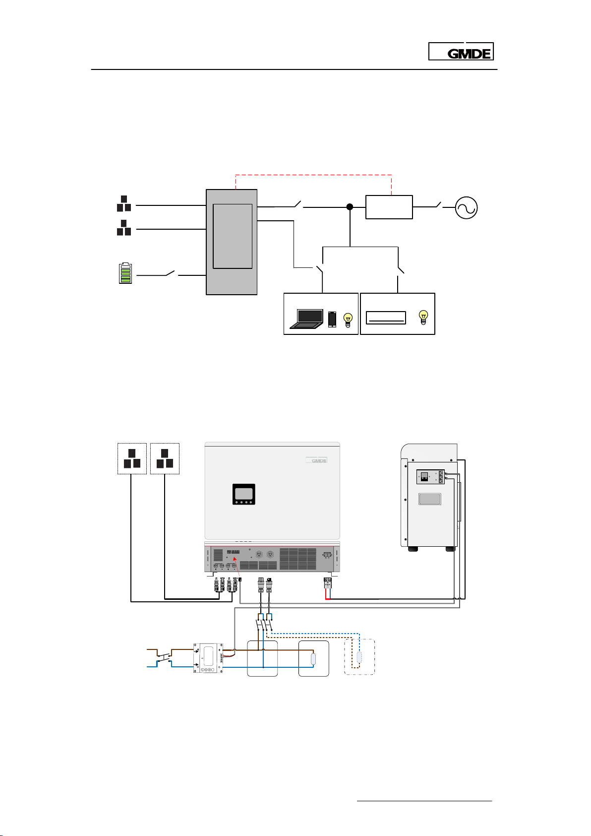
2.1 General System Description ................................................................................... 8
2.2 System Connection................................................................................................. 10
3 System installation .................................................................................................. 10
3.1 Unpacking the Device........................................................................................... 11
3.1.1 Before Unpacking ............................................................................................ 11
3.1.2 Mounting............................................................................................................. 11
3.1.3 Packing List........................................................................................................ 13
3.2 Mounting.................................................................................................................... 15
3.2.1 Powervortex 3700TL Installation.................................................................... 15
3.2.2 Mounting Battery Cabinet............................................................................. 16
3.2.3 Mounting Energy Meter.................................................................................. 19
3.3 System Connection................................................................................................. 21
3.3.1 How to Make Power Connecting Line ....................................................... 22
3.3.2 RS485 Communication Line........................................................................... 22
3.3.3 System Connection ......................................................................................... 23
3.3.4 9.6kWhSystem Connection............................................................................ 24
4 System Settings ....................................................................................................... 25
4.1 LCD .............................................................................................................................. 25
4.1.1 LCD Interface .................................................................................................... 25

Global Mainstream Dynamic Energy Technology Ltd.
- 3 -
User Manual
GHESS 3.7-4.8-SL hybrid system
4.1.2 LCD Indication Lights....................................................................................... 26
4.1.3 LCD Display Definition ..................................................................................... 26
4.1.4 LCD Display Menu Definition......................................................................... 27
4.1.5 LCD Setting Menu ............................................................................................ 27
4.2 Wi-Fi.............................................................................................................................. 38
4.2.1 Wi-Fi Function..................................................................................................... 38
4.2.2 Wi-Fi Configuration........................................................................................... 39
5 System Operation................................................................................................... 42
5.1 System Settings ......................................................................................................... 42
5.2 System Starting ......................................................................................................... 42
5.3 System Operating Instructions.............................................................................. 43
5.3.1 On-grid Operation ........................................................................................... 43
5.3.2 Off-grid Operation ........................................................................................... 43
5.4 System Maintenance.............................................................................................. 43
6 Troubleshooting ...................................................................................................... 44
6.1 Safety during Troubleshooting ............................................................................. 44
6.2 Faults............................................................................................................................ 44
6.3 Fault Messages and Actions List .......................................................................... 44
6.4 Fault Acknowledgement....................................................................................... 46
6.5 Technical Service..................................................................................................... 46

Global Mainstream Dynamic Energy Technology Ltd.
- 4 -
User Manual
GHESS 3.7-4.8-SL hybrid system
Prelude
Published by
Global Mainstream Dynamic Energy Technology Ltd. (GMDE)
3rd Floor, Building 7, Eureka City Industrial Park, No.333 Zhujian Rd,
Minhang District, Shanghai, China.
Tel: +86 21 60710806
Legal Disclaimer
All information in this documentation has been compiled
and checked with most care. Despite of this, errors or
deviations cannot be completely excluded. We assume
no liability therefore.
User is encouraged to check updated version at
http://www.global-mde.com/
Copyright
The details of this documentation are the property of GMDE.
Using and publicizing this documentation, even if only in
parts require the written consent of GMDE

Global Mainstream Dynamic Energy Technology Ltd.
- 5 -
User Manual
GHESS 3.7-4.8-SL hybrid system
Read this user manual before you start
Thank you for purchasing our products, this hybrid solution is highly reliable and efficient. This
GHESS 3.7-4.8-SL system device is IP20 which is only suitable for indoor installation.
If you are reading the electronic version of the manual, please note that you can click the
content to find information you want quickly. All the characters with underline are clickable. A
phrase named ‘Back to Top’ at the bottom of each chapter can help you go back to the first
page quickly.
Before using this device, please ensure that you have read this manual including installation
and safety operation carefully.
If you have any difficulties during installation or operation, please refer to this manual or send

Global Mainstream Dynamic Energy Technology Ltd.
- 6 -
User Manual
GHESS 3.7-4.8-SL hybrid system
1 Safety
1.1 How to Use This Manual
Please read the safety instructions in this manual first. Throughout the manual it is assumed that
the reader is familiar with AC and DC installations and knows the rules and regulations for
electrical equipment and for connecting it to the utility AC grid. It is especially important to be
familiar with the general safety rules for working with electrical equipment.
This manual is intended for qualified electricians.
1.2 Safety Rules
General introduction
These safety-related guidelines use the following warning notices to describe the various levels
of danger:
Danger
Death or severe personal injury will occur.
Warning
Death or severe personal injury may occur.
Caution
Personal injury or material damage may occur.
Explanations
Electric Shock!
Do not open the device! Dangerous voltage may still be applied inside
the device even after it has been switched off.
High leakage current!
Make absolutely sure you establish connection to ground before
connecting the device to the supply circuit!
Health risk!
Health risk for persons with cardiac pacemakers, metallic implants or
hearing aids in the immediate vicinity of electrical equipment!
Risk of improper handling!
Personal injury by crushing, shearing, cutting or striking.
Cancellation of the operating license!
If the GMDE inverter is operated with a wrong country code, the electric
supply company may cancel the operating license.
Hot surface!
Surfaces of the housing can be hot! Risk of injury! Risk of burns.
The housing top and the heat sinks may have a surface temperature of
70°C.

Global Mainstream Dynamic Energy Technology Ltd.
- 7 -
User Manual
GHESS 3.7-4.8-SL hybrid system
1.3 Warning Notices Affixed to the Device
1.4 Important Safety Information
The following operating and maintenance instructions must be read before installing, operating
or maintaining the inverter.
Before installation:
Check for damage on the device and package. If you are in doubt, please contact us or the
distributor before installing the device.
Before connecting the solar modules or battery packs with the product, please check the
voltages and make sure they are within the limits of the GMDE inverter specifications. Failure to
observe these specifications could void your warranty.
Installation:
Only trained and qualified personnel familiar with local electrical codes may work with the
electrical installations. For optimum safety, please follow the steps described in this manual.
Disconnecting the product:
Please refer to “Disconnecting for maintenance” in Section 5.4 System Maintenance. Note that,
after disconnecting the hybrid inverter from AC grid, PV panels and battery packs, wait at least
15 minutes before proceeding.
Operating the product:
Do not commission the device until the whole system complies with the application-specific
national rules and safety regulations.
The ambient conditions given in the product documentation must be observed.
The device manufacturer or installer is responsible for compliance with the limit values as
prescribed in the national regulations.
Only persons who are trained and qualified for the use and operation of this device may work
on the device.
Maintenance and modification:
Only authorized personnel are allowed to repair or modify the inverter. To ensure optimum
safety for user and environment, only the original spare parts available from your supplier should
be used.
WARNING!
Inverter only to be opened by authorized personnel!

Global Mainstream Dynamic Energy Technology Ltd.
- 8 -
User Manual
GHESS 3.7-4.8-SL hybrid system
Functional safety parameters:
Unauthorized changes of functional safety parameters may cause injury or accidents to people
or inverter. Additionally it will lead to the cancellation of all inverter operating approval
certificates.
1.5 Disposal
Please dispose the package and replaced parts according to the rules
applicable in the country where the device is installed. Do not dispose the
GMDE inverter with normal domestic waste.
1.6 Exclusion of Liability
GMDE Technology Ltd. will not be liable for any direct, indirect or consequential damages,
losses, costs or losses including without restriction any economic losses of any kind, any loss or
damage to property, any personal injury, any damage or injury arising from or as a result of
misuse or abuse, or the incorrect installation, integration or operation of the product. We
disclaim any liability for direct or indirect damages due to:
1. Improper installation or commissioning,
2. Modifications, alterations or repair attempts,
3. Inappropriate use or operation,
4. Insufficient ventilation of the device,
5. Non-compliance with relevant safety standards or regulations,
6. Flood, lightning, overvoltage, storm, fire (acts of nature).
We do not assume any liability for an incorrectly set country code. We reserve the right to make
alterations that will improve the function of the device.
2 Description
2.1 General System Description
GHESS 3.7-4.8-SL hybrid system is designed for the new installation of solar battery hybrid system.

Global Mainstream Dynamic Energy Technology Ltd.
- 9 -
User Manual
GHESS 3.7-4.8-SL hybrid system
Figure 1 GHESS 3.7-4.8-SL hybrid system
The system includes three modules: Powervortex 3700TL hybrid inverter, lithium battery packs
and energy meter.
A
B
C
Figure 2 Main system components
A - Powervortex 3700TL hybrid inverter
The hybrid inverter converts the DC power generated by PV modules into AC power. The
generated electricity from PV is used by the household loads, charged into the battery packs or
fed into the grid .
B - Battery packs
Battery packs stores the energy generated from PV generator. Generally each battery
module’s capacity is 2.4kWh; so two battery modules can constitute 4.8kWh battery pack.
C - Energy meter
The 1-phase bi-directional energy meter is for data collection and communication. With the
meter data, the hybrid inverter decides when to charge/discharge the battery packs.

Global Mainstream Dynamic Energy Technology Ltd.
- 10 -
User Manual
GHESS 3.7-4.8-SL hybrid system
2.2 System Connection
The three main components are connected as displayed in Figure 3, which can not only
optimize solar energy self-use and realize peak shaving, but also protect family from power
outages.
Figure 3 System connection
Please add an AC breaker K-grid before the energy meter if users need to switch to off-grid
function manually by disconnecting it, please refer to Figure 4.
PV1 PV2
GRID LOAD
WIFI
CANRS485Ethernet
BAT
Distribution box
L
N
SET
Single Energy Meter
LN
L’N'
5 6 7 8
Load
GMDE
provided Meter Emergency load
PV PANEL Powervortex 3700TL
Battery Cabinet
F1/F2 D3
D4
D2
F3 F4
K-GRID
To Meter
DC
BREAKER
To Inerter
To Cabinet
Figure 4 System connection of manual on/off-grid switching
3 System installation
PV
Smart meter
GRID
K2
BATTERY
DC breaker
D1
RS485
K1
To Grid
To Load
K-inv AC Breaker
K-Grid
Powervortex
3700TL
Emergency Load Load
L’
N’
L
N

Global Mainstream Dynamic Energy Technology Ltd.
- 11 -
User Manual
GHESS 3.7-4.8-SL hybrid system
3.1 Unpacking the Device
3.1.1 Before Unpacking
All products are thoroughly tested and inspected before they’re packed and transported.
Although they’re shipped in reliable package, damage during transportation could still occur.
It is important to inspect the shipping package prior to the installation carefully. If any external
damage on the package makes you suspect the device could be damaged or if you find that
the device is damaged after unpacking it, report the damage immediately to your distributor or
the goods forwarder.
If it becomes necessary to return the device, please use the original packages in which they
were delivered.
The gross weight of Powervortex 3700TL is 35kg. To avoid injury, take the device by the two
holding grips that are visible on the side and take the device out of the package. Ensure a
second person to assist in the unpacking and installation of the devices.
3.1.2 Mounting
1. Don’t install the device in direct sunshine. External heating from exposure to the sun may
cause excessive internal heating. This may result in output power being reduced in order to
protect the internal components from damage.
2. The Powervortex 3700TL hybrid inverter weights 35kg. The installation wall must be vertical and
can carry the weight of the devices.
3. Install the GHESS 3.7-4.8-SL system in a location where the ambient air temperature is less than
45◦C. The GHESS 3.7-4.8-SL may reduce its output power if the ambient air temperature exceeds
45◦C (The cooler the air temperature, the longer the life expectancy of any electronics device).
4. The install space for Powervortex 3700TL and battery cabinet, please refer to the device
dimension figure and installation space figure (Figure 5).
5. The system should be installed in a location where is inaccessible to children.
6. The device is designed for indoor installation (IP20).
7. It is recommended to mount the device at eye level to ensure optimum user comfort.
8. Do not install the system on flammable construction materials, in areas close to flammable or
explosive materials.

Global Mainstream Dynamic Energy Technology Ltd.
- 12 -
User Manual
GHESS 3.7-4.8-SL hybrid system
Figure 5 Powervortex 3700TL dimension
600 245
500
Battery Pack
To Inverter
To Meter
To Meter
DC BREAKER
To Inverter
To Cabinet
Figure 6 Battery cabinet dimension
Module
Powervortex 3700TL
Battery Cabinet
Dimension(L*W*D)
500mm x 660mm x150mm
500mm x 600mm x245mm
Weight
35kg
15kg(cabinet)+25kg*2(battery)
Table 1 Main modules specification

Global Mainstream Dynamic Energy Technology Ltd.
- 13 -
User Manual
GHESS 3.7-4.8-SL hybrid system
Battery Pack
600.0
482.0
500.0
660.0
500.0
300 300
200
200
170.0
245.0
Figure 7 Installation space
3.1.3 Packing List
3.1.3.1 Powervortex 3700TL Packing List
A2
A3
A4
User
Manual
A1
A5
A6
A7
Figure 8 Powervortex 3700TL packing list
Item
Description
pcs
A1
Powervortex 3700TL hybrid inverter
1
A2
Powervortex 3700TL mounting bracket
1
A3
Expansion Tube
6

Global Mainstream Dynamic Energy Technology Ltd.
- 14 -
User Manual
GHESS 3.7-4.8-SL hybrid system
A4
Tapping Screws
6
A5
Aviation Plug Female (for AC grid connection) x 1
1
A6
Aviation Plug Male Connector (for emergency load
connection) x1
1
A7
GHESS 3.7-4.8-SL hybrid system user manual
1
Table 2 Powervortex 3700TL packing list
3.1.3.2 Unpacking Battery Cabinet
B2
B1
B3
B4
Figure 9 Battery cabinet packing list
Item
Description
pcs
B1
Battery cabinet
1
B2
Battery cabinet mounting bracket
1
B3
Expansion Tube
4
B4
Tapping Screws
4
Table 3 Battery cabinet packing list
3.1.3.4 Unpacking Battery Packs
-+
-+
RS485
Link Port0
ON
OFF
COM1COM3 NO1
NO3
SW
POWER
ADD
RUN
Console
SOC
ALM
CAN
Link Port1
IN+
GND
NO2
COM2
Figure 10 48V50Ah battery module (C)
Item
Description
pcs
B
Battery cabinet
1
C
48V50Ah battery module
2

Global Mainstream Dynamic Energy Technology Ltd.
- 15 -
User Manual
GHESS 3.7-4.8-SL hybrid system
Table 4 Battery cabinet packing list
3.1.3.5 Unpacking the Accessories Box
LN
L’N’
5 6 7 8
SET
Single Energy Meter
D1
D2
D3
D4
D5
D6
D7
Figure 11 Accessories box (D) packing list
D1
Energy meter 1-phase
1
D2
Communication line between battery cabinet and energy
meter
1
D3
Power cable between inverter and battery cabinet
1
D4
Communication line between Powervortex 3700TL and battery
packs
1
D5
Battery parallel connection communication cable
1
D6
Battery positive power cable
1
D7
Battery negative power cable
1
Table 5 Accessories box packing list
3.2 Mounting
3.2.1 Powervortex 3700TL Installation
Choose a proper location to install the system according to Figure 12.
3.2.1.1 Mounting Powervortex 3700TL(A1)
1. Choose a proper position for the bracket A2 on the wall and mark it
2. Use Φ10 drill template to drill holes on marked position
3. Fix the expansion bolt A3 into the hole
4. Fix wall bracket A2 on the wall
5. Fix screw A4 through bracket A2 to expansion bolt A3, adjust the bracket position and screw

Global Mainstream Dynamic Energy Technology Ltd.
- 16 -
User Manual
GHESS 3.7-4.8-SL hybrid system
up
6. Align with wall bracket, move Powervortex 3700TL (A1) in horizontal direction to proper
position
7. Make the hook on wall bracket insert into the hole on Powervortex 3700TL(A1)
8. Slowly lower Powervortex 3700TL (A1) , ensure the device hang on the hook of wall bracket A2
9. Check if Powervortex 3700TL (A1) is properly fixed on the wall
Installation demonstration:
Figure 12 Powervortex 3700TL installation demonstration
3.2.2 Mounting Battery Cabinet
3.2.2.1 Install the battery modules into the battery cabinet:
1. Side view on the battery cabinet, and confirm that the “DC BREAKER” is turn off:
To Meter
DC BREAKER
To Inverter
To Cabinet
To Meter
DC BREAKER
To Inverter
To Cabinet
Figure 13 Side view of battery cabinet
2. Open the top cover;
3. Remove the baffle in the middle;

Global Mainstream Dynamic Energy Technology Ltd.
- 17 -
User Manual
GHESS 3.7-4.8-SL hybrid system
4. Put in battery module C;
5. Put on the top cover to finish the battery packs installation into the cabinet.
Figure 14 Installing battery modules into battery cabinet
3.2.2.2 Mounting battery cabinet (B1)
1. Choose a proper position for the bracket B2 on the wall and mark it
2.Use Φ10 drill template to drill holes on marked position
3. Fix the expansion bolt B3 in the hole
4. Fix wall bracket B2 on the wall
5. Fix screw B4 through wall bracket B2 to expansion bolt B3, adjust the bracket position and
screw up
6. Align with wall bracket B2, move Battery cabinet (B1) in horizon direction at proper position.
7. Make the hook on wall bracket B2 insert into the hole on Battery cabinet (B1)
8. Slowly lower Battery cabinet (B1), ensure the device hang on the hook of wall bracket B2
9. Check if Battery cabinet (B1) is properly fixed on the wall
Install demonstration:
Figure 15 Battery cabinet (B1) install demonstration

Global Mainstream Dynamic Energy Technology Ltd.
- 18 -
User Manual
GHESS 3.7-4.8-SL hybrid system
3.2.2.3 Battery Cabinet Electric Wiring Diagram
For 4.8kWh system, pls connect the two battery modules in battery cabinets as below:
1. Insert the “RS485” cable of the battery cabinets to “RS485” port of first battery module, and
take this first battery module as master battery.
2. Connect the port “Link Port 1” of first battery to the port “Link Port 0” of second battery with
the communication cable.
3. The port “Link Port 1” of second battery you can leave it free.
4. Connect one of positive pole of two battery modules and one of negative pole of two
battery modules with the power cables together.
5. Connect another negative pole of battery and another positive pole of battery to DC
breaker of the battery cabinet.
-+
-
-
-
+
+
+
SOC
ALM
SW
AD
D
CAN
RS485
Link Port0
Link Port1
POWE
R
ON
OFF
IN+
COM1COM3 NO1
NO2
NO3
GND
SW
POWE
R
ON
OFF
AD
D
RUN
RUN
Console
Console
SOC
ALM
RS485
CAN
Link Port1
Link Port0
IN+
GND
NO1
COM1
NO2
COM2
NO3
Cabinet 1
D6D7
D5
RS485
1#
2# To Meter
To Inverter
To Cabinet
For 9.6kWh system the power cables connection is same as 4.8kWh, but pls notice the
communication cables connection is different.
1. Insert the “RS 485” cable into port “RS 485” of first battery module and take it as master
battery;
2. Connect port “Link Port 1” of first battery module to port “Link Port 0” of second battery
module with a communication cable;
3. Connect port “Link Port 1” of second battery to battery cabinet with a communication cable;
4. Connect port “Link Port 0” of third battery module to battery cabinet 2;
5. Connect port “Link Port 1” of third battery module to port “Link Port 0” of fourth battery
module with a communication cable.
6. Connect the port “To Cabinet” on battery cabinet 1 to port “To Cabinet” on battery cabinet
2 with a communication cable.

Global Mainstream Dynamic Energy Technology Ltd.
- 19 -
User Manual
GHESS 3.7-4.8-SL hybrid system
-+
-
-
-
+
+
+
SOC
ALM
SW
AD
D
CAN
RS485
Link Port0
Link Port1
POWE
R
ON
OFF
IN+
COM1COM3 NO1
NO2
NO3
GND
SW
POWE
R
ON
OFF
AD
D
RUN
RUN
Console
Console
SOC
ALM
RS485
CAN
Link Port1
Link Port0
IN+
GND
NO1
COM1
NO2
COM2
NO3
Cabinet 1
D6
D7
D5
RS485
1#
2# To Meter
To Inverter
To Cabinet
-+
-
-
-
+
+
+
SOC
ALM
SW
AD
D
CAN
RS485
Link Port0
Link Port1
POWE
R
ON
OFF
IN+
COM1COM3 NO1
NO2
NO3
GND
SW
POWE
R
ON
OFF
AD
D
RUN
RUN
Console
Console
SOC
ALM
RS485
CAN
Link Port1
Link Port0
IN+
GND
NO1
COM1
NO2
COM2
NO3
Cabinet 2
D6D7
D5
RS485
3#
4# To Cabinet
Link Port 0
Figure 16 Battery cabinet electric wiring diagram
Connect the two battery modules as above Figure 16.
Figure 17 Electric Wiring between Powervortex 3700TL and Battery Cabinet
3.2.3 Mounting Energy Meter
The energy meter should be mounted on the AC side of the hybrid system, between the system
and the grid. Generally the energy meter is mounted between the system and the household

Global Mainstream Dynamic Energy Technology Ltd.
- 20 -
User Manual
GHESS 3.7-4.8-SL hybrid system
Gateway meter.
Please notice that the energy meter provided by GMDE cannot replace the household
Gateway meter.
Distribution
box
Load
SET
Single Energy Meter
LN
L’N'
5 6 7
8
Load
Grid
Distribution
box
SET
Single Energy Meter
LN
L’N'
5 6 7
8
Distribution
box
Load
Grid
SET
Single Energy Meter
LN
L’N'
5 6 7
8
Battery Pack Battery Pack
Battery Pack
Grid
☺
☹
☹
Figure 18 Meter position
Please pay attention to the direction of Energy meter, L/N port on the meter is to connect with
the public grid, L’/N’ port is to connect with the “GRID” port of the Powervortex3100/3700TL
hybrid system.
SET
Single Energy Meter
LN
L’N’
5 6 7 8
GRID
Powervortax3100/3700TL
SYSTEM
Figure 19 Mounting energy meter
The meter address set inside the inverter can be read from the label on the meter as shown in
Figure 20 (marked in red as below).
Table of contents
Other GMDE Storage manuals