GMDE GHESS 9.8-14.4-TH User manual

User Manual
3-Phase Residential Energy Storage System
—For GHESS 9.8-14.4-TH——

Global Mainstream Dynamic Energy Technology Ltd.
- 2 -
User Manual
GHESS 9.8-14.4-TH hybrid system
Content
Prelude ............................................................................................................................................................ 4
Read this user manual before you start..................................................................................................... 5
1 Safety............................................................................................................................................................ 6
1.1 How to Use This Manual ........................................................................................................................... 6
1.2 Safety Rules................................................................................................................................................. 6
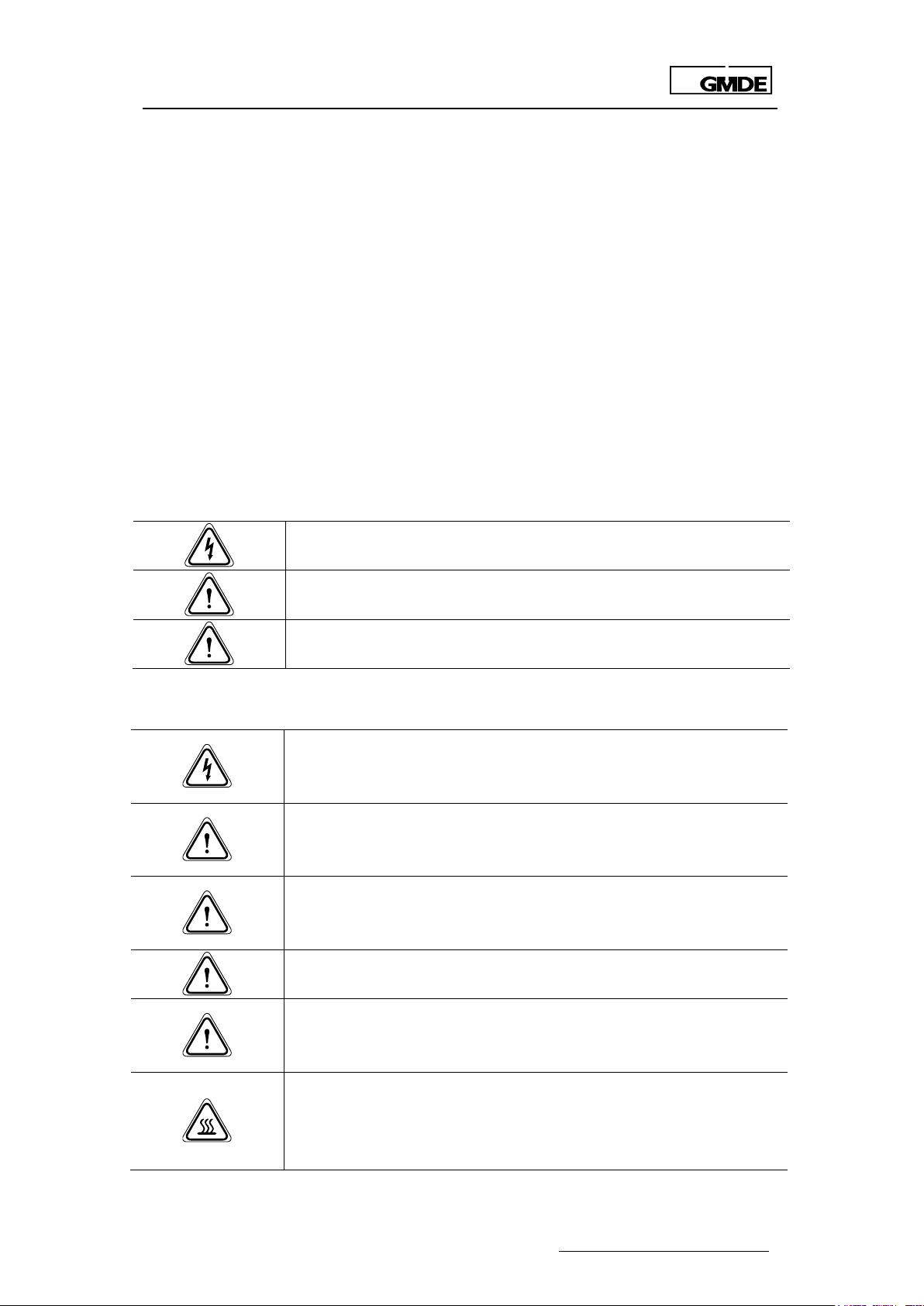
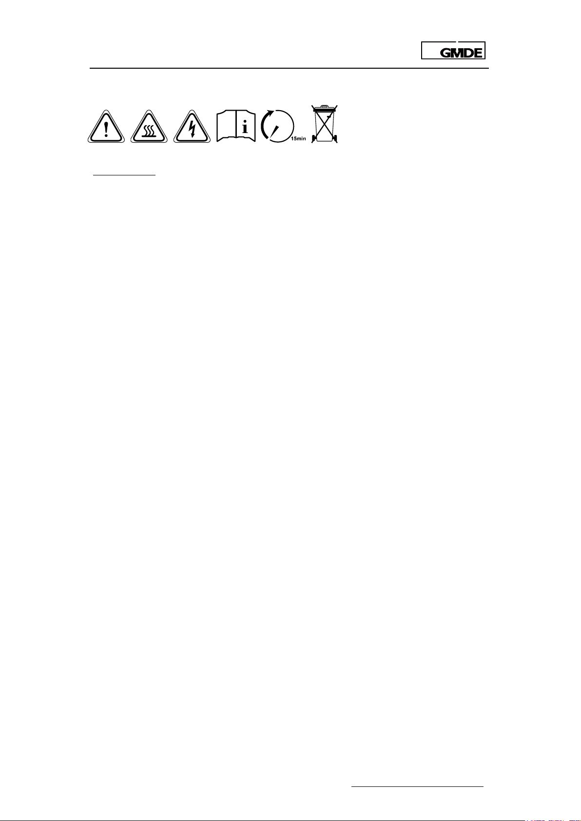
1.3 Warning Notices Affixed to the Device............................................................................................... 7
1.4 Important Safety Information................................................................................................................. 7
1.5 Disposal ........................................................................................................................................................ 8
1.6 Exclusion of Liability................................................................................................................................... 8
2 System Description..................................................................................................................................... 8
3 System Installation.................................................................................................................................... 10
3.1 Unpacking and Install Preparations ................................................................................................... 10
3.1.1 Before Unpacking ........................................................................................................................... 10
3.1.2 Before Mounting.............................................................................................................................. 10
3.1.3 Packing List........................................................................................................................................ 12
3.2 Mounting ................................................................................................................................................... 15
3.2.1 Mounting Hybrid Inverter............................................................................................................... 15
3.2.2 Mounting Battery Cabinet ............................................................................................................ 16
3.2.3 Mounting Energy Meter................................................................................................................. 22
3.3 System Connection ................................................................................................................................ 25
3.3.1 How to Make Power Connecting Line ...................................................................................... 27
3.3.2 RS485 Communication Line.......................................................................................................... 28
4 System Settings ......................................................................................................................................... 28
4.1 LED............................................................................................................................................................... 28
4.1.1 LED Interface .................................................................................................................................... 28
4.1.2 LED Indication Lights....................................................................................................................... 29
4.1.3 LED Display Definition ..................................................................................................................... 29
4.1.4 LED Display Menu Definition ......................................................................................................... 30
4.1.5 LED Setting Menu ............................................................................................................................ 30

Global Mainstream Dynamic Energy Technology Ltd.
- 3 -
User Manual
GHESS 9.8-14.4-TH hybrid system
4.2 Wi-Fi ............................................................................................................................................................. 42
4.2.1 Wi-Fi Function ................................................................................................................................... 42
4.2.2 Wi-Fi Configuration.......................................................................................................................... 42
5 System Operation..................................................................................................................................... 45
5.1 System Settings......................................................................................................................................... 45
5.2 System Starting......................................................................................................................................... 46
5.3 System Operating Instructions.............................................................................................................. 46
5.3.1 On-grid Operation .......................................................................................................................... 46
5.3.2 Off-grid Operation .......................................................................................................................... 47
5.4 System Maintenance ............................................................................................................................. 47
6 Troubleshooting ........................................................................................................................................ 47
6.1 Safety during Troubleshooting ............................................................................................................. 47
6.2 Fault Messages List .................................................................................................................................. 48
6.3 Fault Acknowledgement ...................................................................................................................... 49
6.4 Technical Service .................................................................................................................................... 50

Global Mainstream Dynamic Energy Technology Ltd.
- 4 -
User Manual
GHESS 9.8-14.4-TH hybrid system
Prelude
Published by
Global Mainstream Dynamic Energy Technology Ltd. (GMDE)
3rd Floor, Building 7, Eureka City Industrial Park, No.333 Zhujian Rd,
Minhang District, Shanghai, China.
Tel: +86 21 60710806
Legal Disclaimer
All information in this documentation has been compiled
and checked with most care. Despite of this, errors or
deviations cannot be completely excluded. We assume
no liability therefore.
User is encouraged to check updated version at
http://www.global-mde.com/
Copyright
The details of this documentation are the property of GMDE.
Using and publicizing this documentation, even if only in
parts require the written consent of GMDE

Global Mainstream Dynamic Energy Technology Ltd.
- 5 -
User Manual
GHESS 9.8-14.4-TH hybrid system
Read this user manual before you start
Thank you for purchasing our products, this hybrid solution is highly reliable and efficient. This
GHESS 9.8-14.4-TH system device is IP20 which is only suitable for indoor installation.
If you are reading the electronic version of the manual, please note that you can click the
content to find information you want quickly. All the characters with underline are clickable. A
phrase named ‘Back to Top’ at the bottom of each chapter can help you go back to the first
page quickly.
Before using this device, please ensure that you have read this manual including installation
and safety operation carefully.
Should you have any difficulties during installation or operation, please refer to this manual or

Global Mainstream Dynamic Energy Technology Ltd.
- 6 -
User Manual
GHESS 9.8-14.4-TH hybrid system
1 Safety
1.1 How to Use This Manual
Please read the safety instructions in this manual first. Throughout the manual it is assumed that
the reader is familiar with AC and DC installations and knows the rules and regulations for
electrical equipment and for connecting it to the utility AC grid. It is especially important to be
familiar with the general safety rules for working with electrical equipment.
This manual is intended for qualified electricians.
1.2 Safety Rules
General introduction
These safety-related guidelines use the following warning notices to describe the various levels
of danger:
Danger!
Death or severe personal injury will occur.
Warning!
Death or severe personal injury may occur.
Caution!
Personal injury or material damage may occur.
Explanations
Electric shock!
Do not open the device! Dangerous voltage may still be applied inside
the device even after it has been switched off.
High leakage current!
Make absolutely sure you establish connection to ground before
connecting the device to the supply circuit!
Health risk!
Health risk for persons with cardiac pacemakers, metallic implants or
hearing aids in the immediate vicinity of electrical equipment!
Risk of improper handling!
Personal injury by crushing, shearing, cutting or striking.
Cancellation of the operating license!
If the GMDE inverter is operated with a wrong country code, the electric
supply company may cancel the operating license.
Hot surface!
Surfaces of the housing can be hot! Risk of injury! Risk of burns.
The housing top and the heat sinks may have a surface temperature of
70°C .

Global Mainstream Dynamic Energy Technology Ltd.
- 7 -
User Manual
GHESS 9.8-14.4-TH hybrid system
1.3 Warning Notices Affixed to the Device
1.4 Important Safety Information
The following operating and maintenance instructions must be read before installing, operating
or maintaining the inverter.
Before installation:
Check for damage on the device and package. If you are in doubt, please contact us or the
distributor before installing the device.
Before connecting the solar modules or battery packs with the product, please check the
voltages and make sure they are within the limits of the GMDE inverter specifications. Failure to
observe these specifications could void your warranty.
Installation:
Only trained and qualified personnel familiar with local electrical codes may work with the
electrical installations. For optimum safety, please follow the steps described in this manual.
Disconnecting the product:
Please refer to “Disconnecting for maintenance” in Section
5.4 System Maintenance. Note that, after disconnecting the hybrid inverter from AC grid,
PV panels and battery packs, wait at least 15 minutes before proceeding.
Operating the product:
Do not commission the device until the whole system complies with the application-specific
national rules and safety regulations.
The ambient conditions given in the product documentation must be observed.
The device manufacturer or installer is responsible for compliance with the limit values as
prescribed in the national regulations.
Only persons who are trained and qualified for the use and operation of this device may work
on the device.
Maintenance and modification:
Only authorized personnel are allowed to repair or modify the inverter. To ensure optimum
safety for user and environment, only the original spare parts available from your supplier should
be used.
Functional safety parameters:
Unauthorized changes of functional safety parameters may cause injury or accidents to people
WARNING!
Inverter only to be opened by authorized personnel!

Global Mainstream Dynamic Energy Technology Ltd.
- 8 -
User Manual
GHESS 9.8-14.4-TH hybrid system
or inverter. Additionally it will lead to the cancellation of all inverter operating approval
certificates.
1.5 Disposal
Please dispose the package and replaced parts according to the rules
applicable in the country where the device is installed. Do not dispose the
GMDE inverter with normal domestic waste.
1.6 Exclusion of Liability
GMDE Technology Ltd. will not be liable for any direct, indirect or consequential damages,
losses, costs or losses including without restriction any economic losses of any kind, any loss or
damage to property, any personal injury, any damage or injury arising from or as a result of
misuse or abuse, or the incorrect installation, integration or operation of the product. We
disclaim any liability for direct or indirect damages due to:
1. Improper installation or commissioning,
2. Modifications, alterations or repair attempts,
3. Inappropriate use or operation,
4. Insufficient ventilation of the device,
5. Non-compliance with relevant safety standards or regulations,
6. Flood, lightning, overvoltage, storm, fire (acts of nature).
We do not assume any liability for an incorrectly set country code. We reserve the right to make
alterations that will improve the function of the device.
2 System Description
GHESS 9.8-14.4-TH hybrid system is designed for the new installation of solar battery hybrid
system.

Global Mainstream Dynamic Energy Technology Ltd.
- 9 -
User Manual
GHESS 9.8-14.4-TH hybrid system
Figure 1 GHESS 9.8-14.4-TH hybrid system
The system includes three main parts: Hybrid inverter, LFP battery packs and energy meter.
A
B
C
Figure 2 Main system parts
A. Powervortex 309KTL solar battery hybrid inverter
The hybrid inverter converts the DC power generated by PV into AC power. The generated
electricity from PV is used by the household loads, charged into the battery packs or fed into
the grid.
And the inverter is charging / discharging the battery packs according to commands from
integrated energy management unit.
B. Battery cabinet
Battery packs, an on-/off-grid auto-switching component and system Terminal Box are all
integrated in the Battery Cabinet as shown in Figure 2B.
Battery packs stores the energy and discharges it if necessary. In this system, the standard
nominal capacity is 14.4kWh with 6 battery modules in string connection; a high voltage battery

Global Mainstream Dynamic Energy Technology Ltd.
- 10 -
User Manual
GHESS 9.8-14.4-TH hybrid system
controller is adopted to manage those battery modules and communicate with hybrid inverter.
C. Energy meter
The 3-phase bi-directional energy meter is for data collection and communication. With the
meter data, the hybrid inverter decides when to charge/ discharge the battery packs.
3 System Installation
3.1 Unpacking and Install Preparations
3.1.1 Before Unpacking
All products are thoroughly tested and inspected before they’re packed and transported.
Although they’re shipped in reliable package, damage during transportation could still occur.
It is important to inspect the shipping package prior to the installation carefully. If any external
damage on the package makes you suspect the device could be damaged or if you find that
the device is damaged after unpacking it, report the damage immediately to your distributor or
the goods forwarder.
If it becomes necessary to return the device, please pack them in the original packages that
they were delivered.
3.1.2 Before Mounting
1. Don’t install the device in direct sunshine. External heating from exposure to the sun may
cause excessive internal heating. This may result in output power de-rating to avoid damage on
internal components
2. The Powervortex 309KTL hybrid inverter weights 55kg and Battery Cabinet weights roughly
200kg. The installation wall must be vertical and the floor must be solid to carry the weight of the
devices
3. Install the GHESS 9.8-14.4-TH in a location where the ambient air temperature is less than 45◦C.
As in the system, the inverter may derate the output power if the ambient air temperature
exceeds 45◦C (The cooler the air temperature, the longer the life expectancy of any electronics
device)
4. Please refer to the Figure 3 to Figure 4 with regards to the installing space for GHESS 9.8-14.4-TH
5. The system should be installed in a location where is inaccessible to children
6. The device is designed for indoor installation (IP20)
7. It is recommended to mount the device at eye level to ensure optimum user comfort
8. Do not install the system on flammable construction materials, in areas close to flammable or
explosive materials

Global Mainstream Dynamic Energy Technology Ltd.
- 11 -
User Manual
GHESS 9.8-14.4-TH hybrid system
Figure 3 Powervortex 309KTL dimension
Module
Powervortex 309KTL
Battery cabinet (battery included)
Dimension(L*W*D)
540mmx670mmx289mm
563mm x 1609mm x400mm
Weight
55kg
200kg
Table 1 Mechanical data of inverter and Battery Cabinet

Global Mainstream Dynamic Energy Technology Ltd.
- 12 -
User Manual
GHESS 9.8-14.4-TH hybrid system
Figure 4 Installation space
3.1.3 Packing List
3.1.3.1 Unpacking the Powervortex 309KTL Inverter
User
Manual
A1
A2
A3
A4
A5
Figure 5 Powervortex 309KTL packing list
Item
Description
pcs
A1
Powervortex 309KTL hybrid inverter
1
A2
Powervortex 309KTL user manual
1
A3
Aviation plug (for AC Grid on the Battery Cabinet)
1
A4
Wall bracket
1
A5
Expansion tube (M8*12mm)
4
Table 2 Powervortex 309KTL packing list

Global Mainstream Dynamic Energy Technology Ltd.
- 13 -
User Manual
GHESS 9.8-14.4-TH hybrid system
3.1.3.2 Unpacking Battery Cabinet
The 14.4kWh Battery Cabinet is consisted of 2 parts, the upper and lower Battery Cabinet. The 2
parts are packaged separately.
B1
B2
B3
Figure 6 Battery cabinet packing list
Item
Description
pcs
B1
Upper Battery Cabinet
1
B2
Lower Battery Cabinet
1
B3
Wall lock and screws
4 (SETs)
Table 3 Battery cabinet packing list
3.1.3.3 Unpacking Battery Modules
COM 2
B +B -
STATUS
Link Port 1Link Port 0RS232
Figure 7 H48050A-15S battery module (C)
Item
Description
pcs
C
H48050A-15S battery module
6
Table 4 Battery packing list
3.1.3.4 Unpacking the Accessories Box
S
E
T
Energy Met er
L3 N
L3N
11 12
L2
L2
L1
L1
7 8 9 10

Global Mainstream Dynamic Energy Technology Ltd.
- 14 -
User Manual
GHESS 9.8-14.4-TH hybrid system
D1
D2
D3
D4
D5
D6
D7
D8
D9
D10
D11
D12
D13
D14
Figure 8 Accessories box packing list
Item
Description
pcs
D1
3-phase Energy meter
1
D2
Aviation plug ( to connect with “To Grid” port on the Terminal Box)
1
D3
AC connection cable between inverter “AC GRID” and Battery
Cabinet “To Inverter Output” ports (with aviation plugs) / 1.5m
1
D4
DC connection cable between inverter and Battery Cabinet with MC4
terminals
1
D5
String connecting cable between 2 battery modules “+” & “-“/0.18 m
4
D6
String connecting cable between 2 battery modules in upper and
lower cabinet “+” & “-“/1.0 m
1
D7
Connecting cable between battery module and battery controller
“-”/1.0 m
1
D8
Connecting cable between battery module and battery controller
“+”/0.8 m
1
D9
Communication line between inverter and Battery Cabinet CAN ports/
1.5m
1
D10
Communication line between inverter AS BOX and Battery Cabinet
RS485 ports/ 1.5 m
1
D11
Communication line between inverter RS485 and energy meter ports/
5.0 m
1
D12
Communication line between battery module and controller/ 1.80 m
1
D13
Communication line between battery modules/ 1.00 m
1

Global Mainstream Dynamic Energy Technology Ltd.
- 15 -
User Manual
GHESS 9.8-14.4-TH hybrid system
D14
Communication line between battery modules/ 0.18 m
4
Table 5 Accessories box packing list
3.2 Mounting
3.2.1 Mounting Hybrid Inverter
Choose an adequate location and clearance. Drill holes for the mounting bracket in the wall.
There are only two steps to mount the inverter. The first step is fixing the wall bracket and the
second step is mounting the Powervortex 309KTL. All the steps are shown below by the form of
illustration.
The wall bracket can be fixed to the wall by four expansion bolts (M8*12mm: thread diameter is
8mm, nominal diameter is 12mm). Select the appropriate screw types and dimensions for the
wall material is very important.
Mount the wall bracket according to the following steps:
1. Mark the installation position of wall bracket
2. Remove the wall bracket and then drill installation holes
3. Fix the wall bracket on the wall with screws
4. Tighten up all the screws
Figure 9 Inverter wall bracket mounting
Mount the inverter on the bracket with the following steps:
1. Put the inverter over the bracket and move it in horizon direction
2. Insert the hook on the bracket into in the slot behind the inverter
3. Slowly move down the inverter and hook it on the bracket
4. Fix the inverter on the wall bracket tightly

Global Mainstream Dynamic Energy Technology Ltd.
- 16 -
User Manual
GHESS 9.8-14.4-TH hybrid system
Figure 10 Mounting inverter on the bracket
3.2.2 Mounting Battery Cabinet
3.2.2.1 Wall Lock and Battery Modules Installation
1. Mount the wall lock on the upper and lower Battery Cabinets, as shown below:
Figure 11 Wall lock mounting
1. Open the side door and install the 3 battery modules into the lower Battery Cabinet.

Global Mainstream Dynamic Energy Technology Ltd.
- 17 -
User Manual
GHESS 9.8-14.4-TH hybrid system
Figure 12 Put battery into lower Battery Cabinet
2. Lay the upper Battery Cabinet on the lower Battery Cabinet, lock the upper and lower
Battery Cabinet with screws
Figure 13 Installing Battery Cabinets
3. Install the rest 3 battery modules into the upper cabinet

Global Mainstream Dynamic Energy Technology Ltd.
- 18 -
User Manual
GHESS 9.8-14.4-TH hybrid system
D -D +
B -
B +RS485
CAN
RS232
LinkPort
SOC
STATUS
ADD
OUT1A
RESET
ON/OFF
POWER
OUT1B
OUT2A
OUT2B
OUT3A
OUT3B
OUT4A
OUT4B
IN1A
IN1B
IN2A
IN2B
B +B -
STATUS
LinkPort 1LinkPort 0RS232
B +B -
STATUS
LinkPort 1LinkPort 0RS232
B +B -
STATUS
LinkPort 1LinkPort 0RS232
B +B -
STATUS
LinkPort 1LinkPort 0RS232
B +B -
STATUS
LinkPort 1LinkPort 0RS232
B +B -
STATUS
LinkPort 1LinkPort 0RS232
Figure 14 Side view of battery installation
Fix the 6 battery modules on the cabinet with 24 units of M5*12 screws (each with 4 screws)
After communication and electric connection, close the side doors of the Battery Cabinet
Screw the wall locks of the Battery Cabinets into the wall
3.2.2.2 Wiring inside Battery Cabinet
A Terminal Box and high-voltage battery controller have already been pre-installed in the upper
Battery Cabinet. The electric and communication cables from battery controller to the Terminal
Box are pre-wired as well.

Global Mainstream Dynamic Energy Technology Ltd.
- 19 -
User Manual
GHESS 9.8-14.4-TH hybrid system
Front view of integrated battery controller
and Terminal Box
Back view of integrated battery controller
and Terminal Box
Figure 15 Battery controller and system Terminal Box
Inside the Battery Cabinet, electric wiring and communication line connecting work to be done
are illustrated as below:

Global Mainstream Dynamic Energy Technology Ltd.
- 20 -
User Manual
GHESS 9.8-14.4-TH hybrid system
B +B -
STATUS
Link P ort 1Link P ort 0RS232
B +B -
STATUS
Link P ort 1Link P ort 0RS232
B +B -
STATUS
Link P ort 1Link P ort 0RS232
B +B -
STATUS
Link P ort 1Link P ort 0RS232
B +B -
STATUS
Link P ort 1Link P ort 0RS232
B +B -
STATUS
Link P ort 1Link P ort 0RS232
D -D +
B -
B +RS485
CAN
RS232 LinkPort
SOC
STATUS
ADD
OUT1A
RESET
ON/OFF
POWER
OUT1B
OUT2A
OUT2B
OUT3A
OUT3B
OUT4A
OUT4B
IN1A
IN1B
IN2A
IN2B
B +B -
STATUS
Link Port 1Link Port 0
RS232
B +B -
STATUS
Link Port 1Link Port 0
RS232
B +B -
STATUS
Link Port 1Link Port 0
RS232
B +B -
STATUS
Link Port 1Link Port 0
RS232
B +B -
STATUS
Link Port 1Link Port 0
RS232
B +B -
STATUS
Link Port 1Link Port 0
RS232
D -D +
B -
B +RS485
CAN
RS232 LinkPort
SOC
STATUS
ADD
OUT1 A
RESET
ON/OFF
POWER
OUT1 B
OUT2 A
OUT2 B
OUT3 A
OUT3 B
OUT4 A
OUT4 B
IN1A
IN1B
IN2A
IN2B
Electric wiring diagram
Communication line connection
Figure 16 Line connection
Electric wiring inside Battery Cabinet (with battery module connecting from top to bottom and
from right to left):
Table of contents
Other GMDE Storage manuals
Popular Storage manuals by other brands

Hitachi
Hitachi Virtual Storage Platform G800 reference guide

NETGEAR
NETGEAR SC101 - Storage Central NAS Server Reference manual

Adaptec
Adaptec 29320LPE - SCSI Card Storage Controller U320 320... datasheet

IBM
IBM System Storage TS3500 Introduction and planning guide

asecos
asecos ION-STORE-90 user manual

Tuffy
Tuffy 238 installation instructions

SanDisk
SanDisk microSDHC Specifications

Panasonic
Panasonic CFVFS272W - SUPERDISK DRIVE FOR P.COM operating instructions

Ricoh
Ricoh 5000 installation guide

Sonnen
Sonnen sonnenBatterie eco 8.0/2,5 operating instructions

Kanguru
Kanguru Zipper HD user guide

Infortrend
Infortrend EonStor DS 3000 Series Hardware manual