Godox UL60 User manual

Instruction Manual
705-UL6000-00
Made in China
: 2
: 0755-29609320(8062) : 0755-25723423 : godox@godox.com
godox.com
Add: Building 2, Yaochuan Industrial Zone, Tangwei Community, Fuhai Street, Bao’an District,
Shenzhen, China Tel: +86-755-29609320(8062) Fax: +86-755-25723423 E-mail: [email protected]
GODOX Photo Equipment Co., Ltd.
LED
SILENT LED VIDEO LIGHT

LEDUL60
•
• 2.4GAPPDMX
• 8
•
• U
•
•
•
- 01 - - 02 -
1.
2.
3.
4.
5.
6.
7.
8.
9.
10.
11.
12.
13.
14.

*1 *1
*1
*1
- 03 - - 04 -
*1
*1
*1
•
1.
2.
3. MENU
4. FX
5. DMX
6. SET
7. +-
8. DMX
()
9. DMX
()
10.
11.
12.
13.
14.
15.
16.
SET
MENU FX DMX
-
+
SET
MENU FX DMX
RC-A6

1.
2.
15°
15°
3.
•
LEDLED
- 05 - - 06 -
• AC
V
• V
•
+-
(0~100%)
•
FX
+-FX
8(OFF/1~8),
FX1 FX2 FX3 FX4 FX5 FX6 FX7 Fx8
Flash 1 Flash 2 Flash 3 Storm 1 Storm 2 Storm 3 TV
FXSET
1~8FX
OFFFX
V14.8V
16.8V

LEDUL602.4GRC-A6
2.4G16LED32
99ID
LED(CH),(GR)ID
LED
• 1. 2.4G
MENU+-
CHGRID
CHSET
+-(CH)
(1~32)SET
• CH/GR/ID
GRSET
+-(GR)
(A-F0-9), SET
IDSET
+-ID(1~99 / OFF)
SET
MENU
10
MENU
+-
• 2.
2.1 &
SET2
MENU
LED
()APP
()
APP
2.2 Godox Light
APP
APPAPP
- 07 - - 08 -

3. DMX
DMXDMX
+-
DMX(1~512)
110
- 09 - - 10 -
n()
n+1
n+2
CCT FX
0-51 52-255
DMX*(100/255)
0-100%
DMX*(100/255)
0-100%
DMX*(/255) 8,
DMX=160,
160*8/255=5
SETDMX
DMX
LED
100%(LUX)
1()
CRI
TLCI
(CH)
(GR)
2.4G()
()
()
UL60
AC 100~240V 50/60HZ 0.9A
V 14.8V
60W
5600K±300K
31000
96
97
0~100%
32
16
-10~40
APP/2.4G/DMX
50
225*119*263mm(U)
268*113*64mm
2.38kg
0.94kg
*
• 1
• LED
•
•
•
•
•
: CMIIT ID:2020DP13510

Foreword
Warning
Thank you for purchasing this Godox Product!
Silent LED Video Light UL60 is suitable for live recording, video shooting and
photojournalistic shooting. UL60 is very convenient due to the separation design of
main body and controller. UL series create stable light resource and even illumination
for photography.
Main Features:
• With stable light source and adjustable light brightness
• Can be remote controlled by 2.4G, smartphone APP and DMX
• Support 8 light effects to achieve creative shooting
• Adapter and controller are separate from the main light body, which offers more
convenient operation and better heat dissipation
• With U-type bracket to adjust different angles easily
• Lightweight, portable and suitable for multiple scenes
• Bowens-mount supports various of accessories
Always keep this product dry. Do not use in rain or in damp conditions.
Do not disassemble. Should repairs become necessary, this product must be
sent to an authorized maintenance center.
Keep out of reach of children.
As this product do not have waterproof function, please take measures of
waterproof in rainy or damp environment.
As this product may heat up in working, please do not touch.
Name of Body
1. Main Body
2. Accessory Locking
Button
3. Direction Adjusting
Bracket
4. Reflector
5. Lens
6. Protection Cover
7. Handle
8. Bracket Locking
Screw
9. Fixing Sheet
10. Bracket Sleeve
11. Sleeve Screw
12. Thermovent
13. Power Socket
14. Standard Reflector
- 11 - - 12 -

• Controller
SET
MENU FX DMX
-
+
SET
MENU FX DMX
1. Display
2. Power Switch
3. MENU Button
4. FX Button
5. DMX Button
6. SET Button
7. + - Select Dial
8. DMX Output
Port (male)
9. DMX Output
Port (female)
10. Power Input
11. Power Output
12. Battery Clip
13. Battery Release
Button
14. Battery
Compartment
15. Battery Base
16. Steel Cable
Included Items
Optional Accessory
Light Body *1 Bowens-mount
Reflector *1
Protection
Cover *1 Controller *1
Instruction Manual *1Power Cable *1Connect Cable *1
Purchase more accessories to achieve better shooting experience:
e.g. RC-A6 Remote control, power inverter, softbox, light stand, honey
comb, beauty dish, snoot, etc.
- 13 - - 14 -

Power Supply
Display FX1 FX2 FX3 FX4 FX5 FX6 FX7 FX8
Scene Flash 1 Flash 2 Flash 3 Storm 1 Storm 2 Storm 3 TV Broken bulb
1. Insert the two ends of power source connect
cable into the controller’s power output port and
light’s power input port until a “click” can be
heard.
Pull out the connect cable: press down the
PUSH button and pull out the cable
simultaneously.
2. Insert the power cable’s output end into the
controller’s input port. Then, rotate it rightwards
to 15° until a “click” can be heard.
Pull out the power cable: press the PUSH button
on the output end of power cable and rotate it
leftwards to 15°to pull out.
3. Connect power cable into the power source.
DC Power Supply
Install the V-port battery onto the controller’s
battery compartment. Then, power the light on to
operate.
V-port Battery Power Supply (Optional)
Operation
• Power switch:
Short press the power switch, and the LED light
will be lighted on. Press the button again to turn
off the light.
• Brightness adjustment:
In the main interface, turn the select dial to
adjust brightness from 0% to 100%.
• Light effects setting:
In normal status, short press the FX button once
to enter the setting interface. Then, turn the
select dial to choose light effects from OFF and
1 to 8.
Short press the FX button or SET button to back to the main interface after
settings finished.
Note: If a light effect is selected from 1 to 8, the FX icon and light effects will be
displayed on the main interface. And the brightness can be adjusted. The color
temperature will not be displayed.
If choose OFF, the color temperature will be displayed instead of FX icon.
- 15 - - 16 -
Note: please use the standard V-port battery
with 14.8V standard voltage. Do not supply
power with the battery whose voltage is over
16.8V.

1. 2.4G Wireless Control
Control Mode Selection
With 2.4G wireless system, S60 focusing LED video light has remote grouping
and control function. It is recommended to purchase RC-A6 remote control
(optional) to achieve wireless control. LED lights with 16 groups can be
controlled. 32 channels and 99 IDs are available with strong anti-interference
capability.
Note:
1. Please make LED light's channel, group and ID to the same as remote control's.
2. The wireless signals can only be received in the situation that the LED light is
powered on.
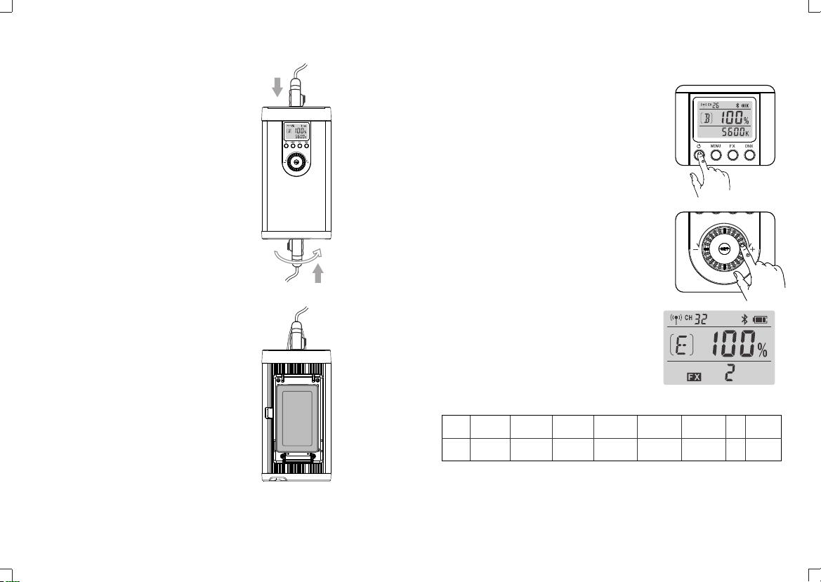
CH Channel Adjustment/GR Group
Adjustment/ID Value Adjustment
In main interface, short press MENU button once
and turn the select dial to adjust channel, group and
ID values.
In CH channel setting interface, short press SET
button and the channel icon will blink. Then, turn the
select dial to choose channel from 1 to 32. Press
the SET button to confirm and the icon will stop
blinking.
In GR channel setting interface, short press SET
button and the group icon will blink. Then, turn the
select dial to choose group from A to F and 0 to 9.
Press the SET button to confirm and the icon will
stop blinking.
In ID channel setting interface, short press SET
button and the group icon will blink. Then, turn the
select dial to choose group from OFF and 1 to 99.
Press the SET button to confirm and the icon will
stop blinking.
After setting all these parameters, short press SET
button to confirm and back to the main interface.
Note: the LED light will auto return to the main
interface if there’s no operation after 10 seconds.
2. Bluetooth Control
2.1 Bluetooth Code Display & RESET Function
Check Bluetooth code: in main interface, short press
MENU button. Then, press the select dial to switch
the icons. The Bluetooth icon will be displayed after
Bluetooth icon appeared.
Bluetooth reset function: in the Bluetooth code
interface, long press the SET button for 2 seconds
and the Bluetooth icon will blink because of
resetting. And the icon will stop blinking after
successfully reset. Then, short press the MENU
button to return to main interface.
Note: The LED light’s Bluetooth function should be
turned on. The APP can be used directly on the firstly
installed device (smartphone or iPad). When change to
other mobile device(smartphone or
iPad), the light shall be reset before the normal
connection of APP.
2.2 Scan the QR code to download the “Godox
Light” smartphone APP(can be used in Android and
Apple).
For more smartphone APP operations, please open
the “help” in APP to gain detailed guidance.
- 17 - - 18 -

Code
n(Mode)
n+1
n+2
CCT FX Note
0-51 52-255
Operation
Mode
DMX*(100/255)
Integer
0-100% Brightness
DMX*(total light
effects/255)
For example: total light
effects 8,DMX=160,
light effects
No.=160*8/255=5
3. DMX Control Mode
In main interface, short press DMX button to
enter the DMX interface and the icon will be
blinking. Then, turn the select dial to set the DMX
channel from 1 to 512. Adjustment in 10 values
quickly or 1 value normally.
DMX Parameters:
DMX*(100/255)
Integer
0-100% Brightness
- 19 - - 20 -
* Product design and specifications are subject to change without notice.
Technical Data
Maintenance
This product, except consumables e.g. battery, power cable and connect cable, is
supported with a one-year warranty.
Avoid sudden impacts and the product should be dedusted regularly.
Maintenance of the flash must be performed by our authorized maintenance
department which can provide original accessories.
Unauthorized service will void the warranty.
If the product had failures or was wetted, do not use it until it is repaired by
professionals.
Changes made to the specifications or designs may not be reflected in this
manual.
Silent LED Video Light
Power Supply
Output Power
Color Temperature
100% Illuminance(LUX)
(1m,darkroom) (≈)
CRI
TLCI
Brightness Range
Channel(CH)
Group (GR)
Working Environment Temperature
Control Method
2.4G Wireless Transmission Distance (≈)
Dimension (≈)
New weight(≈)
UL60
AC Power Supply 100~240V 50/60HZ 0.9A
V-port battery Standard voltage: 14.8V (optional)
60W
5600K±300K
31000
≥96
≥97
0~100%
32
16
-10~40°C
Smartphone APP/2.4G wireless
remote control/ DMX control
50m
Light body: 225*119*263mm
(included U-type bracket and sleeve)
Controller: 268*113*64mm
Light body: 2.38kg
Controller: 0.94kg
Short press SET or DMX button to back to the
main interface after finished all settings.

FCC Statement
This device complies with part 15 of the FCC Rules. Operation is subject to the
following two conditions: (1) This device may not cause harmful interference, and (2)
this device must accept any interference received, including interference that may
cause undesired operation.
Any Changes or modifications not expressly approved by the party responsible for
compliance could void the user's authority to operate the equipment.
Note: This equipment has been tested and found to comply with the limits for a Class
B digital device, pursuant to part 15 of the FCC Rules. These limits are designed to
provide reasonable protection against harmful interference in a residential installation.
This equipment generates uses and can radiate radio frequency energy and, if not
installed and used in accordance with the instructions, may cause harmful interference
to radio communications. However, there is no guarantee that interference will not
occur in a particular installation. If this equipment does cause harmful interference to
radio or television reception, which can be determined by turning the equipment off
and on, the user is encouraged to try to correct the interference by one or more of the
following measures:
- Reorient or relocate the receiving antenna.
- Increase the separation between the equipment and receiver.
- Connect the equipment into an outlet on a circuit different from that to which the
receiver is connected.
- Consult the dealer or an experienced radio/TV technician for help.
Table of contents