Gold Note XS85 User manual

OWNER’S MANUAL
XS85
3 way Modular Floor Standing Loudspeaker
il suono italiano

OWNER’S MANUAL page 1
IMPORTANT SAFETY INFORMATION
CAUTION: TO REDUCE THE RISK OF ELECTRIC SHOCK, DO NOT REMOVE COVER (OR
BACK). NO USER-SERVICEABLE PARTS INSIDE. REFER SERVICING TO QUALIFIED
SERVICE PERSONNEL.
The lightning flash with arrowhead symbol, within equilateral triangle, is intended to alert the
user to the presence of uninsulated “dangerous voltage” within the product’s enclosure that
may be of sufficient magnitude to constitute a risk of electric shock to persons.
The exclamation point within an equilateral triangle is intended to alert the user to the presence
of important operating and maintenance (servicing) instructions in the literature accompanying
the appliance.
This appliance has a serial number located on the rear panel.
Please record the model and serial number and retain them for
your records.
Serial Number: Model:
WARNING
TO PREVENT FIRE OR SHOCK HAZARD,
DO NOT EXPOSE THIS APPLIANCE TO RAIN
OR MOISTURE
Do not disassemble any part of the product.
Do not use any part of the product for other purposes.
For service and problems of any kind, contact qualified Gold Note personnel.
Protect the product from rain and humidity and keep away from heat sources, electric and
electronic motors etc.
The power Chord supplied must be used only on this unit.
Gold Note does not have responsibility for any improper use of this unit

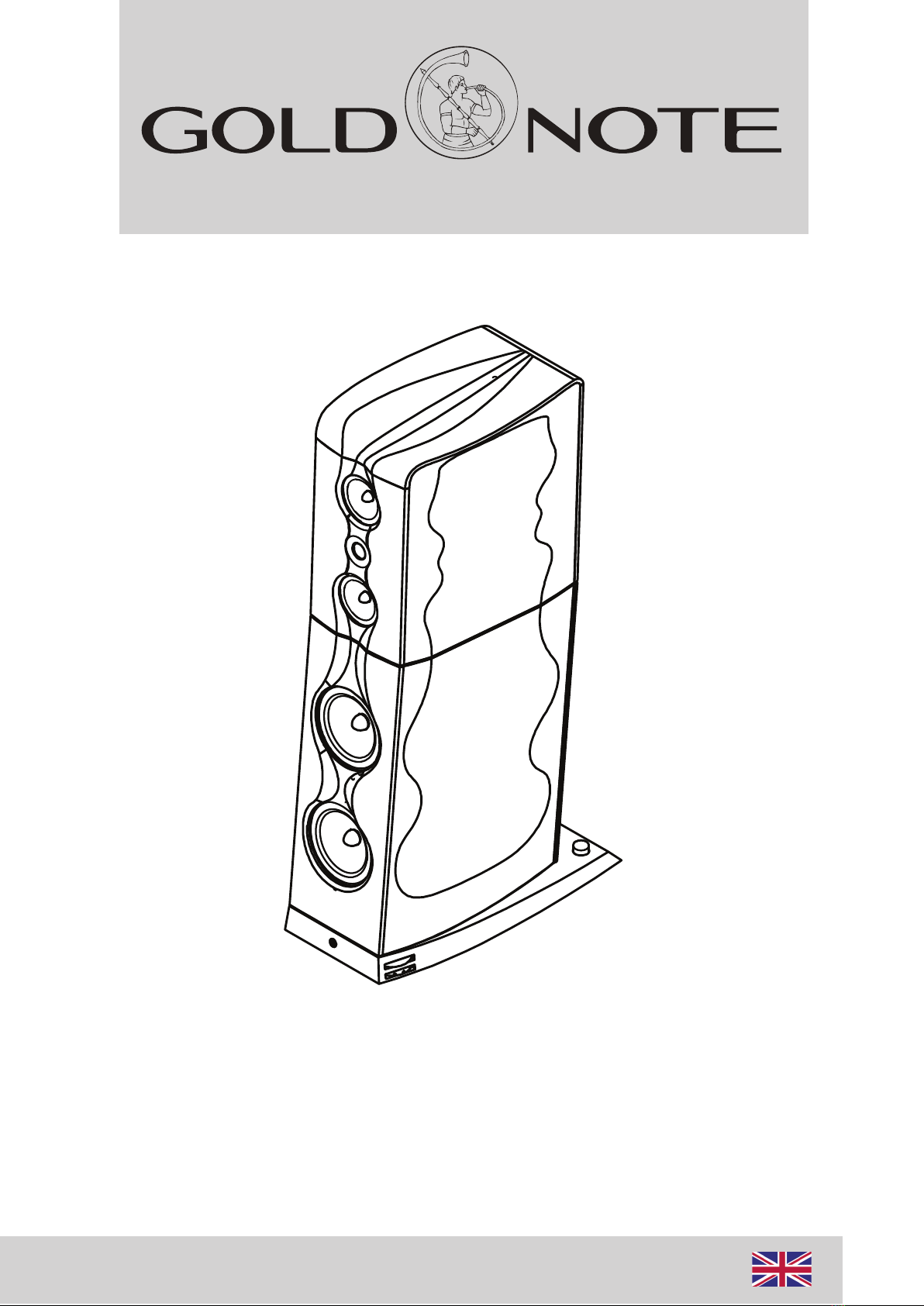
OWNER’S MANUAL page 2
IMPORTANT SAFETY INFORMATION
1Read these instructions.
2Keep these instructions.
3Heed all warnings.
4Follow all instructions.
5Do not use this apparatus near to any water.
6Clean only with dry cloth.
7Do not block any ventilation openings. Install in accordance
with the manufacturer's instructions.
8Do not install near any heat sources such as radiators, heat
registers, stoves, or other apparatus (including amplifiers) that
produce heat.
9Do not defeat the safety purpose of the polarized or ground-
ing-type plug. A polarized plug has two blades with one wider
than the other. A grounding type plug has two blades and a third
grounding prong. The wide blade or the third prong are provid-
ed for your safety. If the provided plug does not fit into your
outlet, consult an electrician for replacement of the obsolete
outlet.
10 Protect the power cord from being walked on or pinched
particularly at plugs, convenience receptacles, and the point
where they exit from the apparatus.
11 Only use attachments/accessories specified by the manufac-
turer.
12 Use only with the cart, stand, tripod, bracket, or table
specified by the manufacturer, or sold with the apparatus. When
a cart is used, use caution when moving the cart/apparatus
combination to avoid injury from tip-over.
13 Unplug this apparatus during lightning storms or when
unused for long periods of time.
14 Refer all servicing to qualified service personnel. Servicing is
required when the apparatus has been damaged in any way,
such as power-supply cord or plug is damaged, liquid has been
spilled or objects have fallen into the apparatus, the apparatus
has been exposed to rain or moisture, does not operate
normally, or has been dropped.
• Do not expose this apparatus to drips or splashes.
• Do not place any objects filled with liquids, such as vases, on
the apparatus.
• Do not install this apparatus in a confined space such as a
book case or similar unit.
• The apparatus draws nominal non-operating power from the
AC outlet with its POWER or STANDBY/ON switch not in the ON
position.
• The apparatus should be located close enough to the AC
outlet so that you can easily grasp the power cord plug at any
time.
• The main plug is used as the disconnect device, the discon-
nect device shall remain readily operable.
• If the product uses batteries (including a battery pack or
installed batteries), they should not be exposed to sunshine, fire
or excessive heat.
• Caution should be taken when using earphones or head-
phones with the product because excessive sound pressure
(volume) from earphones or head- phones can cause hearing
loss.

OWNER’S MANUAL page 3
INTRODUCTION
XS DESIGN
The unique design of our flagship speaker is based on
ultra-rigid, curved and modular panels. These panels are
exclusively hand-crafted in Italy by the most skilled
cabinet-maker.
The high-dampened cabinet is reinforced with a doubled
internal structure and with external wooden multilayer
panels to control resonances and improve the audio
performance. The cabinets conveniently separate the
basses and the mid/highs for a perfect tuning and are
coupled with a 3mm aluminium board to increase the
rigidity of the entire structure even further.
The woofers are installed in a vented cabinet while the
mid/highs are housed in sealed chambers in the upper
cabinet. The upper cabinet also features a second open
chamber with a massive grille made of solid aluminium to
maximize rigidity and reduce internal reflections at the
same time.
The loudspeaker features an integrated heavy-duty stand
made of steel with our innovative hidden adjustable
spikes.
TWEETER
For this loudspeaker we developed a 28 mm ultra-
linear tweeter with an extra-thin and soft silk dome
powered by a neodymium magnet featuring an
aluminium dampening elliptical rear chamber.
This tweeter provides low frequency resonance,
minimal harmonic distortion and an exceptional
musicality making it a real high-quality and High-End
acoustic transducer.
MIDRANGES
The upper cabinet houses two 150mm ultra-linear drivers
that feature high mass phase plugs and Nextel treated
paper cones to reach high rigidity and fast natural audio
response.
Adaptive rubber surrounds provide an ideal match to the
cone over the total frequency range.
The extra large magnet system with long and lightweight
CCAW voice coil allows perfect coil excursion and low
distortion due to excellent transient response.
Solid copper rings are mounted above and below the T-
shaped pole piece to reduce non-linear and modulation
distortions and to increase the overload margin.
The driver is completed by an extremely stiff and stable
skeleton in aluminium/magnesium to avoid airflow noises
and to increase rigidity and lightness.

OWNER’S MANUAL page 4
INTRODUCTION
WOOFERS
The XS-85 speakers feature two 220mm ultra-linear slightly
horn loaded, light drivers with 18gm mass with Nextel
treated paper producing a fast natural audio response in
low frequencies.
The bass drivers feature a large magnet design with
bumped back-plate: the large and dampened platform at
the back improves stiffness while the extra-long and light
weight CCAW voice coil allows extreme coil excursion, low
distortion and excellent transient response.
Giant copper rings mounted above and below the T-shaped
pole piece reduce distortion for better overload margin.
High mass phase plugs reduce compression due to
temperature variations in the voice coil.
Long-term power handling is increased to eliminate
resonances from the cavity inside the voice coil former.
CROSSOVER
The passive Crossover Low-High Dual-Slope with cuts
at 200Hz & 2200Hz is a resistive design that
enables ultra-linear load to handle any sort of
amplification without stressing the power supply,
even at a nominal impedance of 4Ω.
The sophisticated triple crossover network, with
summing midrange multi-slope design, perfectly
integrates the drivers of the array and with anti-
resonance thick glass-fibre boards rewards the
listener with a close field natural audio experience.
Air winding, hand-made coils and selected audio
grade capacitors and exclusive graphite custom GN
resistors complete one of the best crossovers
available today.

OWNER’S MANUAL page 5
SPECIFICATIONS and KEY FEATURES
SPECIFICATIONS
Frequency response: 30 Hz – 30.000 Hz
Sensitivity: 89 dB SPL (2.83V/1 m)
Nominal impedence: 4 ohm semi-resistive
Power handling: 50W – 300W
Suggested min. listening distance: 2.3m
Dimensions: 1280 H x 357 W x 665 mm D
Weight: net 180 Kg (pair), 200 Kg shipping weight
____________________________________________________________________
FINISHES
CABINET & STAND: Matte Black
SIDE PANELS: Glossy Black or Italian Walnut

2 3
OWNER’S MANUAL page 6
UNBOXING AND ASSEMBLY: Woofer Cabinet & Foot
1
4 5
Open the Foot box and gently remove the foot from the box.
Open the Woofer carton box
from the top.
Place the Woofer carton box as shown below.
Gently turn the Woofer carton box upside down as shown in the
picture. Pay attention to the flaps that must be as shown
in fig. 5

OWNER’S MANUAL page 7
UNBOXING AND ASSEMBLY: Woofer Cabinet & Foot
6
7
Gently remove the carton box: the Woofer cabinet should
now be upside down. After removing the bottom protection,
you can go to fig. 7 being ready to assemble the foot to
the Woofer cabinet.
Take the foot as shown in the picture and use the
guides to correctly position the foot on the Woofer cabinet.

OWNER’S MANUAL page 8
UNBOXING AND ASSEMBLY: Woofer Cabinet & Foot
10
8
Allen key
2 x Spikes 5 x Screw M 4 x 45mm
1 x Screw M 4 x 40mm
Yes
No
D o not use the reflex pipes to
m ove the speaker, eventually
handle only the external
flange to avoid any dam age
to the reflex assem bly.
9
Secure the foot to the Woofer Cabinet with 6 screws as shown in
picture with the allen key supplied.
Insert the supplied Spikes in the threaded rear holes of
the metal foot board as shown in the picture.
Once the Foot is assembled, pay extreme care in turning the cabinet
face down as shown in the picture. Make sure to protect it with some
soft material to avoid damaging the surfaces.

2 3
OWNER’S MANUAL page 9
UNBOXING AND ASSEMBLY: Mid-High Cabinet
1
4 5
Gently turn upside down the Mid-High carton box yet CLOSED
Open the box and take care of the box flaps. Repeat the same
operation described for the Woofer Cabinet assembly
fig. 3-4-5

OWNER’S MANUAL page 10
ASSEMBLY: Speaker Modules
Following the pictures, position the Mid-High Cabinet on the Woofer
Cabinet using the guides on the Woofer Cabinet.

OWNER’S MANUAL page 11
ASSEMBLY & INSTALLATION: Speaker Modules and
Aluminium Grille
4 x Screw M 4 x 45mm
Secure the Mid-High Cabinet and the Woofer Cabinet to each other
with the four M4 Allen screws supplied, as shown in the picture.
Connect the Mid-High speak-on terminal to the same
connector of the Woofer Cabinet: Insert it and turn
left in order to lock it in place correctly.
Remove all the screws from the back of the Mid-High Cabinet, then
remove the vented aluminium back grille as shown in the picture.
Place back the vented alumini-
um back grille on the Mid-High
Cabinet and gently secure all
its screws supplied.

OWNER’S MANUAL page 12
HOW TO ADJUST THE FOOT SPIKES
LOCK RELEASE
SPIKE DOWNSPIKE UP
The rear Spikes can be adjusted up and down
with a screwdriver or a 5,5mm wrench.
When the rear spikes are correctly installed, the threaded
black aluminium covers supplied can be positioned to
secure them firmly to the metal foot boards
FRONT SPIKES
REAR SPIKES

OWNER’S MANUAL page 13
CONNECTING the SPEAKERS
-+
-+-+
-+
Stereo Power Amplifier
Right
Speaker
Left
Speaker
R L
Example Connection n. 1
Standard wiring connection (No Bi-Wiring).
Gold Note speakers are all supplied with standard bridge.
Special Exotic Bridge parts of the SIENA BRIDGE ENHANCER line are available on demand

CONNECTING the SPEAKERS
OWNER’S MANUAL page 8OWNER’S MANUAL page 14
-+
-+-+
-+
Stereo Power Amplifier
Right
Speaker
Left
Speaker
R L
Example Connection n. 2
Bi-Wiring Connection
CONNECTING the SPEAKERS

OWNER’S MANUAL page 8
SPEAKER POSITIONING
OWNER’S MANUAL page 15
Identifying the ideal sound/acoustic room to play an audio system well is not that strictly related to the
proportional dimensions of the rooms as many audiophiles believe.
The sound played through an audio system is just “Energy diffused in a closed environment” that is all
absorbed, reflected and dispersed.
The loudspeaker position is the most important aspect because managing the reflections is a key factor to get
the best sound. The first two reflections are crucial, after them the energy of the reflection starts being lower
and does not particularly affect the sound performance.
The first reflection creates a 25m/s delay. Such delay is not favorable because it creates a disturb overwhelming
the sound while the delay in between 40 and 80m/s creates what is called ambience.
Therefore it is very important to reduce the first reflection keeping the speaker as far as possible from the side
walls and using some carpets on the floor in front of them is advisable.
A symmetrical position of the speakers in the room, having the same distance from the side and rear walls is
also very important and should be implemented when possible. The better the positioning the better the focus
and the sound stage will be.
WALL MATERIAL
Generally, most of the walls are thick therefore there is the best bass extension control as well as good acoustic
isolation. Dry walls vibrate quite a bit, therefore they are usually not favorable or should be treated accordingly.
CEILING
The higher the better. The ideal works between 250 and 360cm having the same regular height.
The vaulted ceiling is quite critical because it works like a magnifier lens increasing the power in specific
areas.
In case of an attic where typically the ceiling slopes down it is better to position the speakers closer to
the lower ceiling and place the listening point in the higher ceiling area.
FLOOR
Marble floors are the worst because they are extremely reflecting but even the all carpet floors don’t work well
because they absorb indiscriminately
The best option are wooden floors. In any case, all floors can be easily corrected with a 2/4cm thick carpet
placed in front of the speakers.
SIDE WALLS
Covering the side walls with a carpet is wrong but leaving them naked is not the ideal solution either. Pictures
with frames on the walls are ok if they come without glass protection and are placed symmetrically on both
sides of the speakers. Eventually some small specific traps could be a good solutions.

SPEAKER POSITIONING
OWNER’S MANUAL page 16
REAR WALL
The rear wall does not need to be symmetrical like the side walls but some additional acoustic treatment
will be able to diffract the energy of the sound wave which is important to get good results.
A traditional library with books and records is a very good “no cost” solution.
OPPOSITE WALL
The wall opposite of the stereo system is not that critical. If it is too close to the listening point itself it
would be better covering it with some absorbing material or with a thick curtain.
WINDOWS and DOORS
They always vibrate. It would be better to not have them situated in the room’s corners or in the middle of the side
walls. Treating them with absorbing material could be good but they also must be well closed not waving. Having a
door behind the listening point could work fine once opened.
Curtains in front of the windows should be light to avoid stopping too much energy, except for the optional ones
behind the listening point.
FURNITURE
Ideally, avoid using big furniture with glass/many doors. Open shelf furniture is the best.
If possible, avoid placing the table in between the speakers and the listening point because tables tend to
reflect heavily the high and mid-frequencies.
AUDIO RACKS
Though the best position of audio racks usually is not in the middle of the speakers, some special
racks such like the Gold Note Galileo can beπlaced there because its special all curved shape helps
diffracting the sound waves very well. If you are using standard racks placed in the middle of the
speakers, it is preferable to have rather small ones which enhance a better sound focus.
SUBWOOFER
A general thinking believes the subwoofer does not have any direct emission of sound so the position is not
important. In fact, the energy of the waves generated by the subwoofer creates a sound stage which follows
rules similar to the full range speakers therefore the same rules should be applied to it as well.

OWNER’S MANUAL page 8
SPEAKER POSITIONING
OWNER’S MANUAL page 17
WIDER STEREO SOUND STAGE SPEAKER POSITION
(for some kind of instrumental music, symphonic orcherstra, etc.)
WIDE STEREO IMAGE SPEAKER POSITION
(for some instrument music, synfonic orcherstra etc.)
Listening Point
• The distance of both the speakers to the listening point should be the same
• The distance between both the speakers and the side walls should be the same
• The distance between both the speakers and the rear wall should be the same
The more distance there is between the speakers the wider the sound stage will get but less
focus will the obtained.
To balance the focus, the speakers can be directed to the listening point as indicated in the
images of the pages 18 and 19 of this manual.

SPEAKER POSITIONING
OWNER’S MANUAL page 8OWNER’S MANUAL page 18
NARROWER STEREO SOUND STAGE SPEAKER POSITION
(Optionally for solo instrument music like piano, guitar and voice etc.)
WIDE STEREO IMAGE SPEAKER POSITION
(for some instrument music, synfonic orcherstra etc.)
Listening Point
A reduced distance between the speakers will result in a better focus, while producing a less
realistic sound stage.

SPEAKER POSITIONING
OWNER’S MANUAL page 8OWNER’S MANUAL page 19
DISTANCE BETWEEN SPEAKER AND LISTENING POINT ORIENTATION
Listening Point
A
B
C
The distance between the speakers should be the same as the one to the listening point.
If the distance is shorter, the speaker must be directed to the listening point accordingly (see illustration
above).
Empirical tests are necessary to find the right proportion between wide stereo sound stage focus and
crispy details.
Other manuals for XS85
2
Table of contents
Other Gold Note Speakers manuals

Gold Note
Gold Note XT-7 User manual

Gold Note
Gold Note A6 EVO User manual

Gold Note
Gold Note A6 EVO User manual

Gold Note
Gold Note A3-EVO User manual

Gold Note
Gold Note XS85 User manual

Gold Note
Gold Note XT-7 User manual

Gold Note
Gold Note TUSCANY GOLD User manual

Gold Note
Gold Note A3-EVO User manual

Gold Note
Gold Note A3-EVO User manual

Gold Note
Gold Note XS85 User manual