Goodwe SCB3000 User manual

SCB3000 User Manual
Solar Communication Box
Rev 1.1
2020-11-11

1 Symbol Denition................................................................................................... ...01
2 Installation Instructions and Warnings ............................................ .01
3 Product Introduction............................................................................................. 02
3.1 Product Overview ....................................................................................................................... 02
3.2 Appearance Introduction............................................................................................................ 02
3.3 Packaging Information................................................................................................................ 03
4 Equipment Installation ....................................................................................... 04
4.1 Installation Instructions.............................................................................................................. 04
4.2 Installation Location ................................................................................................................. ..04
4.3 Installation Method ..................................................................................................................... 05
4.4 Port Description .......................................................................................................................... 06
4.5 Wiring Instructions ...................................................................................................................... 07
4.6 Networking Diagrams ................................................................................................................. 10
5 System Operations ................................................................................................... 11
5.1 Indicator Descrition......................................................................................................................11
5.2 Master Computer Operations & Parameter Congurations ...................................................... 13
5.3 Conguration Instructions for Fiber Optic Switches ................................................................. 21
6 Program Upgrade ...................................................................................................... 22
6.1 Local Upgrade ............................................................................................................................. 22
6.2 Remote Upgrade ......................................................................................................................... 22
7 Maintenance and troubleshooting .......................................................... 23
7.1 Maintenance .................................................................................................................................23
7.2 Troubleshooting .......................................................................................................................... 23
8 Technical Parameters ............................................................................................24
9 Certications.................................................................................................................. 24

1 Symbol Denition
Safety Warning - Ignoring the
warning signs in this manual
may cause minor or moderate
injuries.
Danger of high voltage, avoid
electric shock
Recyclable
This side shall be upside, do not tilt
The product must not be
disposed of as ordinary waste,
but must be recycled by special
methods
Stacking limit, up to 4 layers
can be stacked
CE mark Fragile items, handle with care
Avoid humidity
2 Installation Instructions and Warnings
The SCB3000 is designed and tested in strict accordance with relevant safety regulations. However,
as electrical and electronic equipment, the following safety instructions must be observed during
installation and maintenance, and improper operation will cause serious injury and property damage to
the operator and a third party.
• The SCB3000 must be installed and maintained by professionals in accordance with local standards
and regulations.
• When installing and maintaining the SCB3000, power must be disconnected from the SCB3000 to
prevent electric shock.
• During operation, do not touch any live parts of the SCB3000, such as its internal components and
cables, to avoid electric shock.
• Before replacing any components within the SCB3000, power must be disconnected from the
SCB3000 and the newly replaced components must be ensured to meet the requirements for use of
the SCB3000, and GOODWE will not be liable for any personal harms or warranty claims arising from
noncompliance with this instruction.
• When the SCB3000 is in operation, do not plug in or remove any cable.
• The SCB3000 has an internal lightning protection module installed, inside which the PE is connected
to ground when installing the SCB3000.
• Ensure that the AC input voltage and current are matched with the voltage and current ratings of
SCB3000, otherwise the components could be damaged or not functioning properly, and GOODWE
will not be liable for any responsibilities or warranty claims arising from this mismatch.
01

3 Product Introduction
3.1 Product Overview
The SCB3000 is used in photovoltaic power generation systems to integrate data collectors,
allowing for the port aggregation, data acquisition and storage, as well as centralized monitoring and
maintenance of inverters, environment monitors and instrumentations in photovoltaic power generation
systems.
SCB3000 model description:
SCB3000 includes the SCB3000P00 and SCB3000P01. The SCB3000 is the name of the series of
photovoltaic communication boxes; P means that the local communication mode is PLC2.0; 00
means that the cloud communication method supports LAN; 01 means that the cloud
communication method supports LAN and optical bre. In this manual, the SCB3000P00 and
SCB3000P01 models are both referred to as the SCB3000.
Flexible networking:
Communication with inverters supported via PLC or RS485.
Communication with the server available via Ethernet, ber optics, etc.will not be liable for any
responsibilities or warranty claims arising from this mismatch.
Notice: When the SCB3000 uses PLC communication, it can only communicate with inverters supporting PLC2.0.
Currently, inverters equipped with PLC2.0 function include the HT and SMT series. For details, please contact the
Goodwe after-sales service centre.
3.2 Appearance Introduction
After opening the package, check the product to conrm whether it is consistent with the specications
of the SCB3000 you purchased. The appearance of the SCB3000 is shown in Figure 3.2-1.
Solar Communication Box
SCB3000
Figure 3.2-1
02

NO Label Description
1L1/L2/L3/PE Three-phase AC and protective ground wiring port (with a waterproof
cap)
2LAN/ANTENNA Ethernet/Antenna port (with a waterproof cap)
3COM1 RS485-1 port (with a waterproof cap)
4COM2 RS485-2 port (with a waterproof cap)
5COM3 RS485-3 port (with a waterproof cap)
6COM4 RS485-4 port (with a waterproof cap)
7FXL1/FXL2 Fiber Optic Wiring port (with a waterproof cap)
8L/N AC Power Supply port (with a waterproof cap)
3.3 Packaging information
Key×4
..... .. ...
....... ..
..
.. ...
User Manual×1 Expansion Screw×3
Tubular Terminal×2
Fire Clay×1
O-Shaped Terminal×3 Wiring Terminal ×4 Panhead Screw x1
SCB3000×1
SolarCommunication Box
SCB3000
Cable Tie×5
Back Hanger×1
03

4 Equipment Installation
4.1 Installation Instructions
• The SCB3000 is installed in places where there is no signicant shaking, shock or vibration, and not
subject to rain or snow.
• The installation height shall be parallel to the line of sight for easy operation and aintenance.
• The installation location of the SCB3000 should be free of explosive media containing gases and
dust sufcient to corrode metals and damage insulation.
• The parameter labels and warning signs must be clearly visible after the SCB3000 is installed.
• The installation location of the SCB3000 shall avoid sunlight, rain, and snow.
Avoid sunlight Avoid rain Avoid snow
Sunlight Rain Snow
4.2 Installation Location
The following factors must be considered when choosing the installation location:
• The installation method and location must be suitable for the weight and size of the SCB3000.
• Install on a solid surface.
• The installation location must be sufciently ventilated.
• The SCB3000 can be horizontally placed or vertically installed.
• The vertical installation or tilt back can not exceed 15 degrees, must not be tilted sideways, the
wiring area should be facing down, as shown in Figure 4.2-1.
Solar Communication Box
SCB3000
MAX
15°
Figure 4.2-1
04

• To ensure good heat dissipation and easy disassembly, the minimum clearance around the SCB3000
must not be less than the following values, as shown in Figure 4.2-2.
Solar Communication Box
SCB3000
Figure 4.2-2
Top
Bottom
Front
Both sides
4.3 Installation Method
Vertical Installation:
1. Drill holes in the wall with a diameter of 8mm and a depth of 45mm. The spacing of the holes is
shown in Figure 4.3-1.
2. Use the expansion screws in the accessory pack to x the back plate on the wall, as shown in
Figure 4.3-2.
Mounting Backplate
Expansion Tube
Tapping Screw
Figure 4.3-1 Figure 4.3-2
250mm
125mm
25mm
3. Install the enclosure as shown in Figure 4.3-3.
Figure 4.3-3
L
o
Install the SCB3000 enclosure bracket on the back plate and tighten it securely with screws to
prevent the enclosure from shaking.
05

Horizontal Placement:
1. The SCB3000 can be placed horizontally, as shown in Figure 4.3-4.
2. The SCB3000 needs to be placed indoors at a location where it can be xed, as shown in Figure
4.3-5.
Figure 4.3-4 Figure 4.3-5
4.4 Port Description
The internal ports of SCB3000 are described as follows:
RUN FXL1FXL1B
DI
NET REF1 REF21 2 3 A BA B A B A B4
COM1 COM2 COM3 COM4
FXL1 FXL2
RESET
APWR FXL2
TP1 TP2 TP3
1000M ACT1000M ACT1000M ACT
12V
POWER
NO Port Port Description
1POWER DC Power Input (occupied)
2NET Ethernet (occupied for ber optic version)
3DI DRED (for Australia) or RCR (for Germany) function
4NC Reserved
5COM1 RS485 port for communications with the inverter
6COM2 RS485 port for communications with the inverter
7COM3 RS485 port for communications with the inverter
8COM4 For connections to third-party equipment such as environment monitors
9TP1, TP2 Ethernet (for ber optic version only)
10 TP3 Ethernet (occupied, for ber optic version only)
11 FXL1, FXL2 Fiber Optical Port (for ber optic version only)
Notice: Item numbers 9, 10 and 11 in the above list are ber optic module ports, and will only be used when the ber
optic version is selected. These 3 ports will not exist if there is no ber optic version. Ports 5, 6 and 7 are RS485
ports, and will not be used when the SCB3000 is communicating with inverters through the PLC.
06

4.5 Wiring Instructions
(1) (2) (3) (4) (5)
POWER NET REF1
DI COM1COM2 COM3COM4
REF22 3 4 A B A B A B A B1
FXL2FXL1
PE
4.5.1 Description of SCB3000 Power Supply Cable
The single-phase power supply cable is connected to the internal single-phase switches L and N of the
SCB3000.
Input phase voltage range: AC100V~AC240V; AC frequency: 50Hz/60Hz
Input wire and crimping:
10~12mm
L
N
Plier Crimping
Flexible stranded copper wire
AB
C D
Code Description Value
AWire outer diameter No greater than 25mm
BCross-sectional area of copper conductors Recommend for use: 2.5~4mm²
CWire length Approximately 45mm
D Copper bare wire length Approximately 12mm
Notice: Before connecting the AC power line, make sure that the switch upstream of SCB3000 is open.
07

4.5.2 PLC Wiring Instructions
(a) Protective Earth Wiring:
The protective ground wire is connected to the PE of the base plate of inside the SCB3000 enclosure.
(b) Remove the three-phase AC power line cover panel.
(c) Connect the three-phase AC power line.
Notice: Before connecting the AC power line, make sure that the switch upstream of SCB3000 is open.
Three-phase input line voltage range: AC342V~AC800V; AC frequency: 50Hz/60Hz.
The three-phase AC power line is connected to the transformer bus, and then to the circuit breakers L1, L2 and L3 in
the SCB3000 via port (1).
(d) Install the three-phase AC power line cover panel.
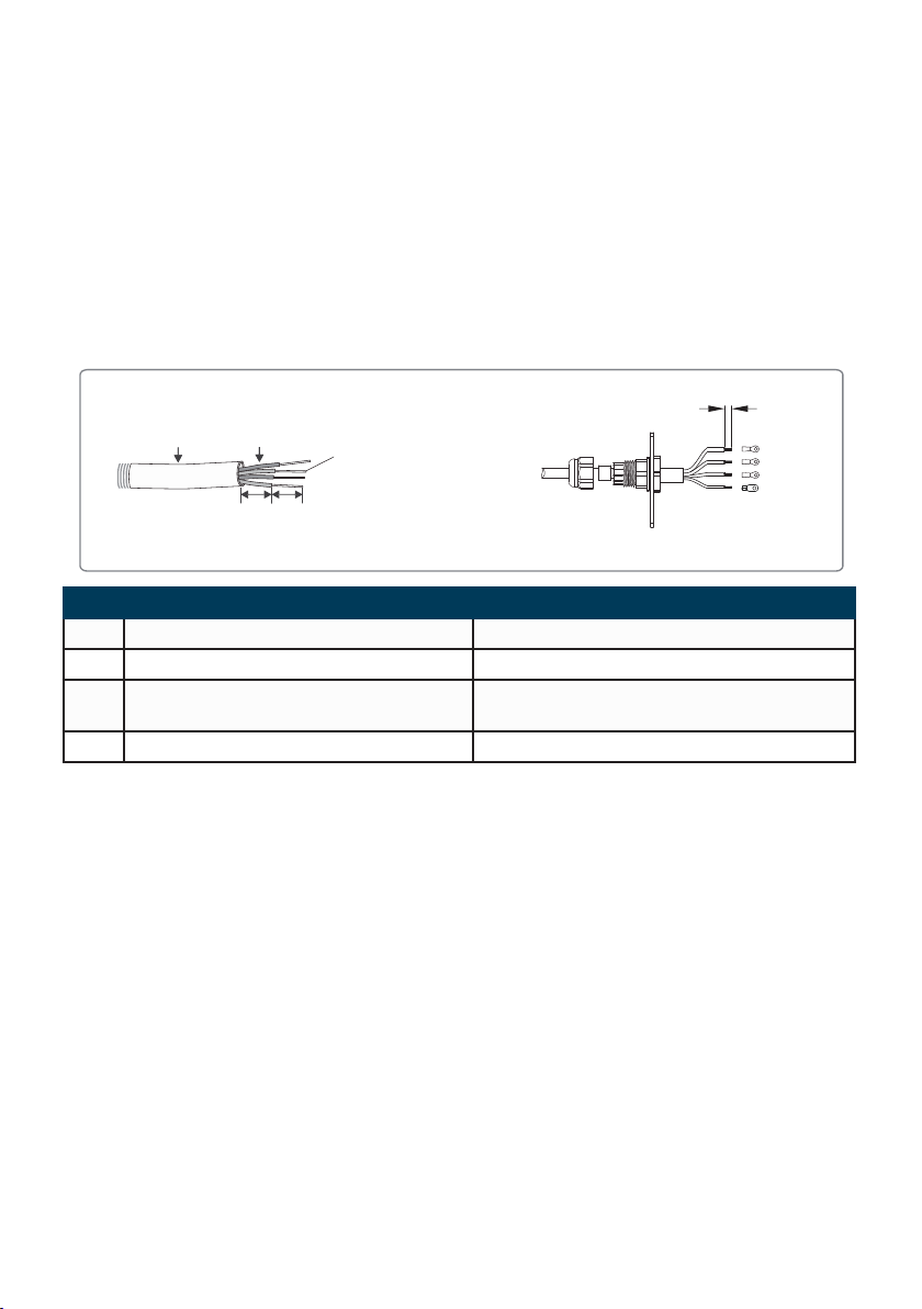
AC Input wire specications and crimping:
Plier Crimping
6~8mm
L1
L2
L3
PE
Flexible stranded copper wire
AB
C D
Code Description Value
A Wire outer diameter No greater than 25mm
B Cross-sectional area of copper conductors Recommend for use: 2.5~4mm²
C Wire length Approximately 130mm (approximately 50mm
for PE wire)
D Copper bare wire length 6~8Mm (5~6mm for PE wire)
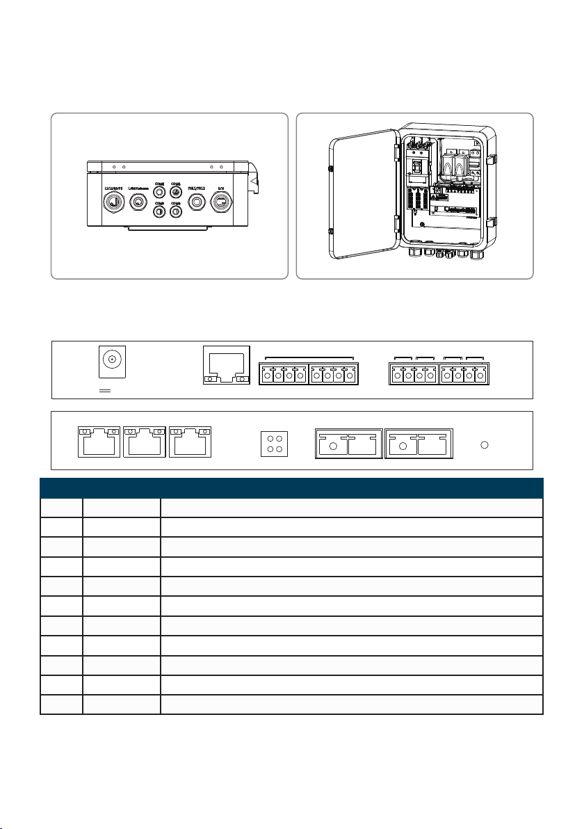
4.5.3 Description of RS485 communication wiring
COM1, COM2 and COM3 are RS485 ports for communications with the inverter that can be left
unused if communications with inverter PLC can meet the requirements, users can choose to connect
COM1, COM2 or COM3 for communications with the inverter as needed.
If using the SCB3000 to connect with a environment monitor, the connection can be made to the
COM4 port via the RS485 cable.
Notice: 1. COM1, COM2 and COM3 are used only for communications with the inverter, while COM4 is only
connected to third-party equipment such as environment monitors, and must not be connected incorrectly.
2. For RS485 communication wiring, please use standard RS485 communication twisted pair.
3. The maximum number of inverters connected to each of COM1, COM2 and COM3 is 20 units, with the total of 60
units allowed for the 3 ports.
4. In the ports COM1, COM2, COM3 and COM4, A corresponds to the differential signal +, and B corresponds to the
differential signal.
Wire specications and installation: for RS485 communication cables, shielded twisted pair cables with
a conductor cross-sectional area of 1mm² are recommended for use.
08

Screw Nut
Isolator
Gasket
Nut
Cable
Box
6.5mm
25mm
Wire No Functions
1RS485+
2RS485-
4.5.4 Description of LAN communication wiring
The SCB3000 can be connected to routers, computers, switches and other equipment through the
network cable; The network cable is connected to the internal NET port of the SCB3000; if you select
the ber optic version of this device, the network cable can be connected to the TP1 or TP2 port (the
NET port has been connected to the TP3 port for the ber optic version of this device).
Cat 5e is recommended for use as the network cable. After wiring, please use the re clay included to
block it to ensure its reproof performance.
4.5.5 Description of ber optic communication wiring
The SCB3000 ber optic version can be connected to ber optic terminals through optical cables for
data transmission.
The optical cables are connected to the FXL1 and FXL2 ports inside the SCB3000.
Notice: Both ends of the same ber optic must be connected to the TX and RX ports, otherwise the ber optic
connection will not be made correctly.
4.5.6 Wiring instructions for other ports
The DI port of SCB3000 is compatible with both RCR (for Germany) and DRED (for Australia)
functions. The port denitions in different functions are as follows:
REF1 1 2 3 4 REF2
RCR +5V D_IN1 D_IN2 D_IN3 D_IN4 +5V
DRED RefGen DRM1/5 DRM2/6 DRM3/7 DRM4/8 Com/DRM0
If the user does not need to use this function, the port does not need to be wired.
09

4.6 Networking Diagrams
PV string
DC Cable
Inverter
Inverter
AC Combiner Box
Transformer
Grid
Three-phase AC
power line
Fiber Optic Device
Environment Monitor
Router
Network Cable
Inverter
DC Cable
DC Cable
PV string
PV string
Standalone
Multi-machine fiber optic
ring network
Environment
Monitor
Inverter
Transformer
Environment
Monitor
Inverter Transformer
Router
Fiber optic ring
network
1
2
3
45
One of the SCB3000s need to be set as the master (root node), with the others as the slaves (slave
nodes).
10

5 System Operations
5.1 Indicator Description
Port Status Status Description
POWER Blue Light On The power supply is OK
Blue Light Off The power supply is Off
RUN
Blue Light ashing (on for 1 second,
off for 1 second)
The SCB3000 is not operating properly
Blue Light On or Off continuously The SCB3000 is operating properly
SERVER
Blue Light On continuously The SCB3000 is connected to the external
network server correctly.
Blue Light ashing (on for 1 second,
off for 1 second)
The SCB3000 is connected to the router
correctly, but not connected to the external
network server.
Blue Light Off No network connection for SCB3000
PC
Blue Light On The SCB3000 is connected to a computer and
ProMate software
Blue Light Off The SCB3000 is not connected to a computer
and ProMate software
COM1
Blue Light On The actual number of inverters acquired by
SCB3000 is equal to the number of acquired
inverters set for the port
Blue Light ashing (on for 1 second,
off for 1 second)
The actual number of inverters acquired by
SCB3000 is less than the number of acquired
inverters set for the port
Blue Light ashing (on for 1 second,
off for 3 seconds)
The number of inverters acquired by SCB3000
is not set for the port
Blue Light Off The SCB3000 has not acquired any data from
the inverter
COM2
Blue Light On The actual number of inverters acquired by
SCB3000 is equal to the number of acquired
inverters set for the port
Blue Light ashing (on for 1 second,
off for 1 second)
The actual number of inverters acquired by
SCB3000 is less than the number of acquired
inverters set for the port
Blue Light ashing (on for 1 second,
off for 3 seconds)
The number of inverters acquired by SCB3000
is not set for the port
Blue Light Off The SCB3000 has acquired data from the
inverter
11

Port Status Status Description
COM3
Blue Light On The actual number of inverters acquired by
SCB3000 is equal to the number of acquired
inverters set for the port
Blue Light ashing (on for 1 second,
off for 1 second)
The actual number of inverters acquired by
SCB3000 is less than the number of acquired
inverters set for the port
Blue Light ashing (on for 1 second,
off for 3 seconds)
The number of inverters acquired by SCB3000
is not set for the port
Blue Light Off The SCB3000 has not acquired any data from
the inverter
COM4
Blue Light On Other equipment (such as external environment
monitors) communication good
Blue Light Off No other equipment, such as external
environment monitors
12

5.2 Master Computer Operations & Parameter Congurations
ProMate is a software released by us for the conguration of the SCB3000 functions, it enables the
modication of the network IP address of the SCB3000, the conguration of the number of port-
connected inverters, time settings, RCR and DRED feature conguration, eld debugging and more.
5.2.1 Connecting to the Master Computer Software
If the user wants to congure the SCB3000 using ProMate software, the master computer needs to be
connected in either dynamic IP (DHCP) or static IP according to the way the network is connected.
1. SCB3000 dynamic IP address connection:
SCB3000 is set to dynamic IP mode by default, and the network connection is simply made by
connecting the SCB3000 NET port to the router LAN port with the network cable, which is plug and
play. To congure the SCB3000, connect your computer to the router with a network cable, and launch
the ProMate software in which you can click "Scan" to complete the connection successfully. When the
conguration is complete, disconnect the computer from the router.
Notice: If the SCB3000 is set to static IP mode, you need to switch to dynamic IP mode before you can congure
it using dynamic IP connection. Press and hold the "RELOAD" button for about 4 seconds, this will make the LED
signal indicators ash from right to left, indicating a completed reset and restart, after which the SCB3000 will be
switched to static IP mode.
2. SCB3000 static IP address connection:
Notice: SCB3000 is set to dynamic IP mode by default, you need to switch the SCB3000 to static IP mode rst by
pressing and holding the "RELOAD" button for about 10 seconds, this will make the LED signal indicators of the
SCB3000 ash from right to left, indicating a completed reset and restart, after which the SCB3000 will be switched
to static IP mode (the default IP address is 192.168.1.200).
The user needs to set the computer to static IP mode, and congure the computer's IP address and
the SCB3000's IP address in the same network segment. The steps are as follows (using Windows
7 OS as an example). Users can nd the methods on the Internet that can be used to modify the IP
addresses of computers running different operating systems.
13

(a) Use a network cable to connect the "NET" of the SCB3000 to the Computer's Ethernet port.
(b) Right-click “Network" and select "Properties".
(c) Click "Change adapter settings".
(d) In the local connection popup dialog box, right-click "Local connection" and click "Properties".
14

The following popup dialog box is displayed:
(e) Double-click "Internet Protocol Version 4 (TCP/IPv4)" to show the "Internet Protocol Version 4
(TCP/IPv4)" popup dialog box, and set up the dialog box according to the requirements below. The
default IP address of the SCB3000 is 192.168.1.200. To keep the computer and SCB3000 in the
same network segment, the "IP address" and "Default Gateway" should be set at the 192.168.1.XXX
segment (1≤XXX≤250 and XXX≠200).
For example: The IP address can be set to 192.168.1.100 and the default gateway 192.168.1.254.
15

Click the "Connect" button in ProMate, when it shows that the connection is successful, ProMate is
connected to the SCB3000 successfully.
Notice: If there is only one Box-type substation on the customer site, and the data is uploaded to GOODWE servers,
there is no need to congure the box number and address through ProMate, simply connect ProMate, click to get the
inverter list to see if the inverter is all online. If there are multiple box Box-type substations onsite, refer to 5.2.2 for
setup.
5.2.2 Parameter Congurations (for PLC communication with the inverter)
When the connection to ProMate is successful, parameter congurations can be made on the
SCB3000 and the inverter to which it is connected.
(a) Choose Protocol
Click the "Ezlogger Pro" button and select the protocol in the following popup.
Custom is used for parameter conguration and Modbus protocol for normal communication.
The machine is set to "Custom" in the factory by default, and the following protocol showed in grey is
the one that is currently used. After switching protocols, ProMate waits about 1 minute to proceed.
16

Notice: Select the GOODWE custom protocol rst to congure the BOX No and inverter address, then switch to the
Modbus protocol for communications after all parameters have been congured.
(b) Settings of Device Count and Box No
Enter numbers for both "Device Count" and "Box No".
For "Device Count", enter the number of inverters actually connected to the current SCB3000. The
"Box No" is used to identify the Box-type substations onsite. (For example, if there are multiple
SCB3000s in use onsite, they must be corresponding to different box numbers) As shown below: the
number of inverters connected to the SCB3000 on-site is 3, so the "Device Count" of 3 in entered.
Notice: The Device Count and Box No are required, the devices will not function properly if either eld is not lled in.
As shown below: When nished setting the Device Count and the Box No, you can click the "Read"
button to see if the settings are successful.
17

(c) Inverter Address Conguration
Connecting the SCB3000 to the inverter requires the Modbus address to be congured, with the option
of one click and manual operation available for the inverter address conguration.
As shown below: Click the "One key cong" button, and the software randomly assigns the inverter
address.
As shown below: Click the "Set" button to see if the conguration is successful.
18
Other manuals for SCB3000
2
Table of contents