Goodwe BCL0096 User manual

Installation Manual
Smart Hybrid Battery Enclosure BCL0096 V1.0
340-00429-00

Notice of copyright
GoodWe Smart Hybrid Battery Enclosure Installation Manual 2017 by GoodWe Technologies. All
Rights Reserved. This work is copyright, apart from any use permitted under the Copyright Act
1968. No part may be reproduced by any process, nor may any other exclusive right be
exercised without the permission of GoodWe Technologies Limited.
Privacy notice
GoodWe will use the information provided only for warranty purposes. Without this information
we will not be able to process your warranty claim. If you require further information about our
privacy policy please visit our website at goodwe.com.

Tools required
. Spirit level
. Battery drill with Phillips tec bit
. Assorted screw drivers
. Allen key set
Location and environmental requirement
. The Battery Enclosure is rated IP54, so it can be installed both indoors and outdoors.
. If installed outdoors, the enclosure should not be mounted on a east or west ward facing wall or
any location that exposes the enclosure to direct sunlight. It should also be mounted under-
neath a shelter to protect it from the weather.
. The Battery Enclosure should be mounted against a reasonably flat, structurally sound wall and
it needs to be standing on a level surface.
. There should be no flood risk at the location selected for the Battery Enclosure installation.
. There should be ample room (min 150mm) for air circulation around the Battery Enclosure as the
Battery Enclosure uses fans to circulate air, the air intake and expulsion grills on the right and left
hand side of the Battery Enclosure should not be blocked at any time.
Expansion Bolts x 8 Short Grounding
Wire x 3
Long Grounding
Wire x 3
External Ground
Screw x 2
Internal Ground
Screw x 5
Hexagon Screw of
top cover x 5 Lock Bracket x 4 Countersunk Screw x 10
Glue
Table of contents
Parts Listᅠ................................................................................................................................................... 4
Tools required .......................................................................................................................................... 4
Location and environmental requirement .......................................................................................... 4
Dimensions ................................................................................................................................................ 5
Preparation .................................................................................................................................................... 6
Mounting and enclosure .............................................................................................................................. 7
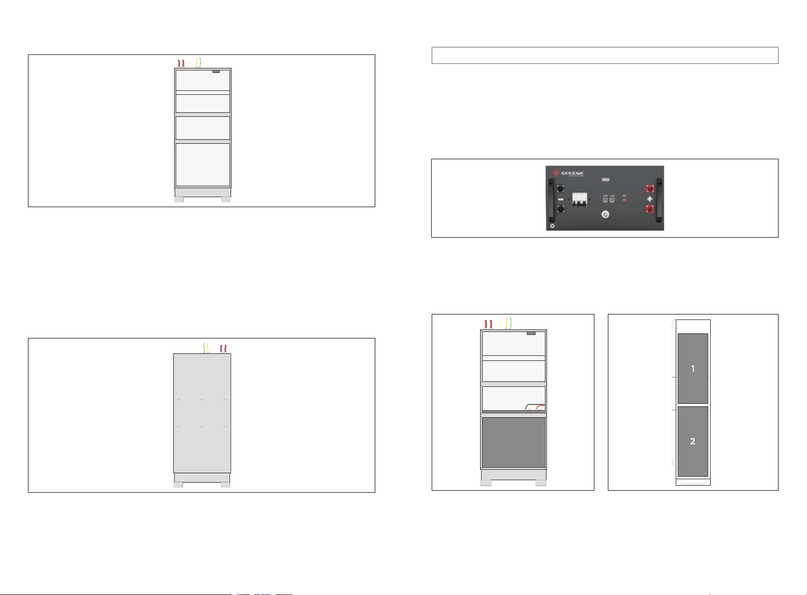
Inserting the batteries ................................................................................................................................... 7
BMS Connection ......................................................................................................................................... 10
BMS battery connections table ................................................................................................................. 11
Connecting the Battery Enclosure to the Inverter .................................................................................. 12
Commissioning ............................................................................................................................................ 13
Parts List
01 02

535mm
1205mm
1205mm
280mm
Feet Inside bottom view of Enclosure without feet
Dimensions
Preparation
The Battery Enclosure dimensions are: width 535mm, depth 280mm, height 1155mm (without the
feet installed) and width 535mm, depth 280mm, height 1205mm (with the feet installed).
Figure 1: Dimensions
Figure 2: BCL0096 out of the packing box.
Figure 3: Battery Enclosure feet and mounting screws.
1.In preparation for the installation of the enclosure, take off the three front covers of the Battery
Enclosure by removing the 12 screws.
2.Screw the two feet to the base of the Battery Enclosure, using the three screws provided.
03 04

3.Once the feet are fixed, the Battery Enclosure is ready for installation as shown in Figure 4.
Note: The battery switch should remain off during the installation process.
The enclosure can be used to house Li-ion battery types,the following installation uses GoodWe
SECU-A battery as an example.
. Up to two GoodWe SECU-A (4.8kWh) battery packs with a total storage capacity of 9.6 kWh.
1.Insert the batteries onto the shelves one at a time by inserting the battery pack bottom first into
the cabinet. Please fill the cabinet from bottom to top, insert battery 2 first ,then 1 (see figure
8).
Figure 6: GoodWe SECU-A battery front handles.
Figure 7: BCL0096 with the bottom battery
inserted
Figure 8: Inside view of BCL0096 with two
GoodWe SECU-A batteries.
2.Once the batteries are placed into position, plug the respective power leads into the power
connectors on the batteries while taking note of the polarity. Ensure that the battery 2 lead
which has the power connector for the Fan Controller is plugged into one of the batteries.
Figure 4: Battery Enclosure with the feet attached and ready for installation.
Figure 5: BCL0096 wall mounting holes.
3.Once the enclosure is fixed onto the wall, apply generous amount of the supplied sealant on the
six screw holes to seal off any moisture ingress points.
Inserting the batteries
Mounting the enclosure
The Battery Enclosure is designed to be installed below the Inverter and comes prewired for easy
integration with GoodWe Inverter.
1.Set the Battery Enclosure against the wall. Ensure that the floor where the Battery Enclosure is
to be installed is level.
2.Use the supplied fixing screw and plug set to fix the enclosure onto the wall. An alternative fixing
mechanism can be employed if the supplied screw and plug set is not appropriate for the wall.
05 06

Figure 9: BCL0096 earthing connection points.
Figure 10: BCL0096 with batteries and connected (GoodWe SECU-A).
At this stage the preliminary installation of the Battery Enclosure is complete. The next step is the
connection of the BMS cables.
3.If you are using GoodWe SECU-A battery packs, connect the bonding leads between each battery
and the earthing studs inside the enclosure.
BMS connection
The BMS communication for GoodWe SECU-A battery is as follows:
GoodWe SECU-A
2x earthing points
2x earthing points
2x earthing points
Side of Battery Enclosure
(wire-frame view)
2x earthing points
Fan Controller
Front view of Battery Enclosure
DIP Switch Calibration
The DIP switches shall be configured differently between single piece battery and 2 battery
paralleling system.
2* Pack System (10.8kWh)
1* Pack System (5.4kWh)
Function
Terminal Resistance Switch
GoodWe communication protocol Switch
DIP
2
3
Description
To recognize the last battery connected to inverter
To relize the communication between inverter and inverter unit part
07 08
1234
ON DIP
1234
ON DIP
1234
ON DIP

Figure 11: GoodWe SECU-A
Battery 2 +/-port
To Inverter
Cabinet of battery
Link
491.9965
ON
WI-FI
PV isolator
Backup
25 amp 400Vac
2-pole circuit breaker
Earth
Utility grid
40 amp 400Vac
2-pole circuit breaker
Manual AC load
25 amp 250Vac
bypass switch
Grid main
230V utility grid
connection terminals
Battery
125 amp per pole80/125VDC
2-pole circuit breaker
switch board
FAN 1
Power Supply Connect to Battery
FAN 2
BMS to GoodWe SECU-A‘CAN’port
BMS battery connection table
Description
GoodWe SECU-A
(Figure 12)
BMS feed through port
Fan Controller To
Battery port
Link Port COM 2 of the
master battery
Master battery COM 1
port to Inverter port
Link port COM 1 of the
slave battery
From To Cable label
APP Setting (On PV Master)
To make sure the battery communicates to inverter unit successfully, users have to use PV
Master to choose the right battery option on PV Master:
APP Installation And Connection:
Connect phone & Inverter
Wi-Fi SSID: Solar-WiFi***
Password: 12345678
Download
and install
PV Master
play
App Store
09 10
Select “SECU-A5.4L” on battery page
in PV Master Application
Notes:
1. Select wrong battery will lead to BMS
communication failure
2. For the complete commissioning of
the whole ESA system, please go to
ESA instruction.
Select Battery on PV master
Select Battery Model
GoodWe
BYD
GCL
LG
PYLON
DYNESS
AlpahESS
eSTORE
SECU-A5.4L*1
SECU-A5.4L*2

Figure 12: BCL0096 Battery Enclosure connected to Inverter (GoodWe SECU-A). Figure 13: The completed installation of BCL0096
ON
Connecting the Battery Enclosure to the Inverter Commissioning
The inverter should be powered down during this process. Please refer to
the Inverter’s installation Manual for the shutdown sequence.
The Battery Enclosure is now ready to be connected to the Inverter mounted on the same wall
above the Battery Enclosure as per figure 13.
Please note you should refer to the Inverter’s installation manual for details on how to mount the
Inverter.
1.Connect the Amphenol connectors, on the top of the Battery Enclosure, to the matching battery
connectors at the base of the Inverter.
Note: You need to check the Inverter’s commissioning steps to complete the commissioning of
the whole system,
2.Connect the Battery Enclosure’s earth lead to the earth terminal inside the Inverter.
3.With the Inverter’s BoS box and the Battery Enclosure’s front cover still open, turn on the Invert-
er and subsequently close the battery breaker in preparation for the commissioning process.
CAUTION! GoodWe Battery (SECU-A)
1.Ensure all the BMS connections have been done as per the instruction provided in this installa-
tion manual (page10)
2.You don’t need to assign the battery (ADD) addresses manually as the master battery will do this
for you (provided the BMS wiring is done per the instruction in this installation manual.
3.Press the Battery Breaker on all batteries. The green LED light should light up. (Please note that
the batteries won’t be discharging any power at this stage).
4.Press the Battery Switch on the master battery. That will start all batteries.
5.The ‘Battery’ light on the Control Board should be on, indicating that BMS communication has
been established between the master battery and the Inverter and at this stage you should be
able to see the battery on the portal in the APP.
Note: You need to check the Inverter’s commissioning steps to complete the commissioning of
the whole system as per the Inverter’s manual.
11 12

Notes
13
Other Goodwe Enclosure manuals