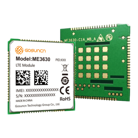
GOSUNCN GM500-U1G A User manual

Hardware Development Guide
Version: V1.0
Date: 2020-11-20
LTE Module Series
GM500-U1G_A
Website: www.gosuncnwelink.com
E-mail: welink@gosuncn.com

All Rights reserved, No Spreading without GOSUNCN PermissionI
GM500-U1G_A
Hardware Development Guide
Revision History
Version Date Description
1.0 2020-11-20 1st released version

All Rights reserved, No Spreading without GOSUNCN PermissionII
GM500-U1G_A
Hardware Development Guide
About This Document
A. Application Range
This document is the Product Technical Specification for the GM500-U1G_AGSM/WCDMA/LTE-FDD module. It defines the high
level product features and illustrates the interface for these features. This document is intended to cover the hardware aspects of
the product, including electrical and mechanical.
B. Reading Note
The symbols below are the reading notes you should pay attention on:
: WARNING or ATTENTION : NOTE or REMARK
C. Purpose
This document provides the hardware solutions and development fundamentals for a product with the module. By reading this
document, the user can have an overall knowledge of the module and a clear understanding of the technical parameters. With this
document, the user can successfully fulfill the application and development of wireless Internet product or equipment.
Besides the product features and technical parameters, this document also provides the product reliability tests and related
testing standards, RF performance indexes and a guide on the design of user circuits, to provide the user with a complete design
reference.
NOTE:
To ensure the module manufacturing and welding quality, do as the chapter 7 of Manufacturing Guide in
this document. The force on the squeegee should be adjusted so as to produce a clean stencil surface on a
single pass and ensure the module soldering quality.
D. Abbreviations
Table below is a list of abbreviations involved in this document, as well as the English full names.
Abbreviations Full Name
3GPP Third Generation Partnership Project
AP Another name of DTE
CHAP Challenge Handshake Authentication Protocol
CE European Conformity
CMOS Complementary Metal Oxide Semiconductor
DCE Data Communication Equipment
DL Downlink
DTE Data Terminal Equipment
EIA Electronic Industries Association
EMC Electromagnetic Compatibility
ESD Electro-Static discharge
ESR Equivalent Series Resistance
FDD Frequency Division Duplex
GPIO General-purpose I/O
LCC Leadless Chip Carrier

All Rights reserved, No Spreading without GOSUNCN PermissionIII
GM500-U1G_A
Hardware Development Guide
LDO Low-Dropout
LED Light Emitting Diode
LTE Long Term Evolution
ME Mobile Equipment
MO Mobile Origination Call
MT Mobile Termination Call
MSB Most Significant Bit
PC Personal Computer
PCB Printed Circuit Board
PDA Personal Digital Assistant
PDU Protocol Data Unit
PAP Password Authentication Protocol
PPP Point to Point Protocol
RTC Real Time Clock
SMS Short Messaging Service
SMT Surface Mount Technology
SPI Serial Peripheral Interface
TBD To Be Determined
TCP Transmission Control Protocol
TIS Total Isotropic Sensitivity
TRP Total Radiated Power
TVS Transient Voltage Suppressor
UART Universal Asynchronous Receiver-Transmitter
UDP User Datagram Protocol
UL Up Link
USB Universal Serial Bus
USIM Universal Subscriber Identity Module
URC Unsolicited result code
VIH Logic High level of input voltage
VIL Logic Low level of input voltage
VOH Logic High level of output voltage
VOL Logic Low level of output voltage

All Rights reserved, No Spreading without GOSUNCN PermissionIV
GM500-U1G_A
Hardware Development Guide
Safety Information
The following safety precautions must be observed during all phases of the operation, such as usage, service or repair of any
cellular terminal or mobile incorporating ME3610 module. Manufacturers of the cellular terminal should send the following safety
information to users and operating personnel and to incorporate these guidelines into all manuals supplied with the product. If not
so, GOSUNCN does not take on any liability for customer failure to comply with these precautions.
Full attention must be given to driving at all times in order to reduce the risk of an accident. Using a
mobile while driving (even with a hands free kit) cause distraction and can lead to an accident. You must
comply with laws and regulations restricting the use of wireless devices while driving.
Switch off the cellular terminal or mobile before boarding an aircraft. Make sure it switched off. The
operation of wireless appliances in an aircraft is forbidden to prevent interference with communication
systems. Consult the airline staff about the use of wireless devices on boarding the aircraft, if your device
offers a Airplane Mode which must be enabled prior to boarding an aircraft.
Switch off your wireless device when in hospitals or clinics or other health care facilities. These
requests are designed to prevent possible interference with sensitive medical equipment.
GSM cellular terminals or mobiles operate over radio frequency signal and cellular network and
cannot be guaranteed to connect in all conditions, for example no mobile fee or an invalid SIM card. While
you are in this condition and need emergent help, please remember using emergency call. In order to make
or receive call, the cellular terminal or mobile must be switched on and in a service area with adequate
cellular signal strength.
Your cellular terminal or mobile contains a transmitter and receiver. When it is on, it receives and
transmits radio frequency energy. RF interference can occur if it is used close to TV set, radio, computer or
other electric equipment.
In locations with potentially explosive atmospheres, obey all posted signs to turn off wireless devices
such as your phone or other cellular terminals. Areas with potentially explosive atmospheres including
fuelling areas, below decks on boats, fuel or chemical transfer or storage facilities, areas where the air
contains chemicals or particles such as grain, dust or metal powders.

All Rights reserved, No Spreading without GOSUNCN PermissionV
GM500-U1G_A
Hardware Development Guide
Contents
Revision History ........................................................................................................................................................................... I
About This Document ....................................................................................................................................................................... II
Safety Information ......................................................................................................................................................................... IV
Contents .......................................................................................................................................................................... V
Tables ....................................................................................................................................................................... VIII
Figures .......................................................................................................................................................................... X
1. Product Overview ....................................................................................................................................................................... 12
1.1. General Description ........................................................................................................................................................................... 12
1.2. Key Features ................................................................................................................................................................................. 12
1.3. Function Diagram............................................................................................................................................................................... 13
1.4. Evaluation Board ................................................................................................................................................................................ 14
2. Application Interface ................................................................................................................................................................... 15
2.1. General Description ........................................................................................................................................................................... 15
2.2. Pin Assignment ................................................................................................................................................................................. 15
2.3. Pin Description ................................................................................................................................................................................. 16
2.4. Power Supply ................................................................................................................................................................................. 24
2.4.1. Power Supply Pins ................................................................................................................................................................... 24
2.4.2. Decrease Voltage Drop ............................................................................................................................................................ 25
2.4.3. Reference Circuit of Power Supply .......................................................................................................................................... 25
2.5. Turn on Scenarios .............................................................................................................................................................................. 26
2.6. Turn off Scenarios .............................................................................................................................................................................. 28
2.7. Reset Scenarios ................................................................................................................................................................................. 29
2.8. USIM Card Interface........................................................................................................................................................................... 31
2.8.1. Description of USIM pins ......................................................................................................................................................... 31
2.8.2. Design Considerations for USIM Card Holder .......................................................................................................................... 32
2.9. USB Interface ................................................................................................................................................................................. 35
2.10. UART Interface ................................................................................................................................................................................. 37
2.10.1. UART CONNECTION ............................................................................................................................................................... 37
2.10.2. UART LEVEL MATCH .............................................................................................................................................................. 38
2.10.3. Use ic for level switch ............................................................................................................................................................ 43
2.11. Network Status Indication ............................................................................................................................................................... 44
2.12. POWER_ON/OFF Status Indicator ON_STATE .................................................................................................................................. 45
2.13. ADC Interface ................................................................................................................................................................................. 46
2.14. WAKEUP_IN Signal ........................................................................................................................................................................... 47
2.15. WAKEUP_OUT Signal ....................................................................................................................................................................... 48

All Rights reserved, No Spreading without GOSUNCN PermissionVI
GM500-U1G_A
Hardware Development Guide
2.16. GPIO Interface ................................................................................................................................................................................. 49
2.17. USB_BOOT ................................................................................................................................................................................. 50
2.18. SD Card Interface ............................................................................................................................................................................. 50
2.19. SGMII Interface ................................................................................................................................................................................ 52
3. Antenna Interface ....................................................................................................................................................................... 54
3.1. Pin Definition ................................................................................................................................................................................. 54
3.2. Reference Design ............................................................................................................................................................................... 54
3.3. Reference PCB Layout of Antenna ..................................................................................................................................................... 56
3.4. Suggestions for EMC & ESD Design .................................................................................................................................................... 56
3.4.1. EMC Design Requirements ...................................................................................................................................................... 56
3.4.2. ESD Design Requirements ....................................................................................................................................................... 56
3.5. Test Methods for Whole-Set Antenna OTA ....................................................................................................................................... 57
4. Electrical, Reliability and Radio Characteristics ............................................................................................................................ 58
4.1. Absolute Maximum Ratings ............................................................................................................................................................... 58
4.2. Operating Temperature ..................................................................................................................................................................... 58
4.3. Electrostatic Discharge ...................................................................................................................................................................... 58
4.4. GM500-U1G_A Test ........................................................................................................................................................................... 58
4.4.1. Current Consumption .............................................................................................................................................................. 58
4.4.2. RF Output Power ..................................................................................................................................................................... 59
4.4.3. RF Receiving Sensitivity ........................................................................................................................................................... 59
4.5. GNSS Technical Parameters ............................................................................................................................................................... 60
5. Mechanical Dimensions .............................................................................................................................................................. 61
5.1. Mechanical Dimensions of the Module ............................................................................................................................................. 61
5.2. Footprint of Recommendation .......................................................................................................................................................... 62
6. Related Test & Test Standard ...................................................................................................................................................... 64
6.1. Testing Reference .............................................................................................................................................................................. 64
6.2. Description of Testing Environment .................................................................................................................................................. 64
6.3. Reliability Testing Environment ......................................................................................................................................................... 65
7. SMT Process and Baking Guide .................................................................................................................................................... 66
7.1. Storage Requirements ....................................................................................................................................................................... 66
7.2. Module Plainness Standard ............................................................................................................................................................... 66
7.3. Process Routing Selection .................................................................................................................................................................. 66
7.3.1. Solder Paste Selection ............................................................................................................................................................. 66
7.3.2. Design of module PAD’s steel mesh opening on main board .................................................................................................. 66
7.3.3. Module Board’s SMT process .................................................................................................................................................. 67
7.3.4. Module Soldering Reflow Curve .............................................................................................................................................. 68
7.3.5. Reflow method ........................................................................................................................................................................ 69
7.3.6. Maintenance of defects .......................................................................................................................................................... 69
7.4. Module’s Baking Requirements ......................................................................................................................................................... 69
7.4.1. Module’s Baking Environment ................................................................................................................................................ 69
7.4.2. Baking device and operation procedure ................................................................................................................................. 70

All Rights reserved, No Spreading without GOSUNCN PermissionVII
GM500-U1G_A
Hardware Development Guide
7.4.3. Module Baking Conditions ...................................................................................................................................................... 70

All Rights reserved, No Spreading without GOSUNCN PermissionVIII
GM500-U1G_A
Hardware Development Guide
Tables
Table 1-1 GM500-U1G_A Supported Band .................................................................................. 12
Table 1-2 GM500-U1G_A Key Features....................................................................................... 12
Table 2-1 IO Parameters Definition .............................................................................................. 17
Table 2-2 Logic levels Description ................................................................................................ 17
Table 2-3 Pin Description ............................................................................................................. 17
Table 2-4 Power Supply ............................................................................................................... 25
Table 2-5 Definition of POWER_ON ............................................................................................. 27
Table 2-6 Power-on Time ............................................................................................................. 28
Table 2-7 Power-off Time ............................................................................................................. 28
Table 2-8 Pin Definition of the USIM Interface .............................................................................. 31
Table 2-9 Pin Description of Molex USIM Card Holder ................................................................. 33
Table 2-10 Pin Description of Amphenol USIM Card Holder ......................................................... 34
Table 2-11 USB Pin Description ................................................................................................... 35
Table 2-12 Pin Definition of the Main UART Interface .................................................................. 37
Table 2-13 Pin Definition of the Debug UART Interface ................................................................ 37
Table 2-14 Pin Definition of Network Indicator .............................................................................. 44
Table 2-15 Working State of the Network Indicator ...................................................................... 45
Table 2-16Pin Definition of ON_STATE .......................................................................................... 45
Table 2-17 Pin Definition of the ADC ............................................................................................ 46
Table 2-18 Characteristic of the ADC ........................................................................................... 46
Table 2-19 ADC interface features(1/3 scaling)............................................................................... 46
Table 2-20 ADC interface features(x1 scaling) ................................................................................ 47
Table 2-21 Pin Definition of WAKEUP_IN .................................................................................... 47
Table 2-22 Pin Definition of WAKEUP_OUT ................................................................................ 48
Table 2-23 Pin Definition of GPIO ................................................................................................ 50
Table 2-24 Pin Definition of USB_BOOT ........................................................................................ 50
Table 2-24 Pin Definition of SD controller Interface ......................................................................... 50
Table 2-24 Pin Definition of SGMII Interface ................................................................................... 52
Table 3-1 Pin Definition of Antenna .............................................................................................. 54

All Rights reserved, No Spreading without GOSUNCN PermissionIX
GM500-U1G_A
Hardware Development Guide
Table 4-1 Absolute Maximum Ratings .......................................................................................... 58
Table 4-2 Operating Temperature ................................................................................................ 58
Table 4-3 ESD characteristic ........................................................................................................ 58
Table 4-4 Averaged standby DC power consumption [1] .............................................................. 58
Table 4-5 Averaged working current [1] ........................................................................................ 59
Table 4-6 Averaged working current [2] ........................................................................................ 59
Table 4-7 Conducted RF Output Power........................................................................................ 59
Table 4-8 Conducted RF Receiving Sensitivity Typical Value [1] .................................................. 59
Table 4-9 Conducted RF Receiving Sensitivity Typical Value [2] .................................................. 60
Table 4-10 GNSS Technical Parameters ...................................................................................... 60
Table 6-1 Testing Standard .......................................................................................................... 64
Table 6-2 Testing Environment .................................................................................................... 64
Table 6-3 Testing Instrument & Device......................................................................................... 65
Table 6-4 Reliability Features ....................................................................................................... 65
Table 7-1 Baking parameters ....................................................................................................... 66
Table 7-2 LCC module PAD’s steel mesh opening ................................................................................ 66

All Rights reserved, No Spreading without GOSUNCN PermissionX
GM500-U1G_A
Hardware Development Guide
Figures
Figure 1–1 System Connection Structure ..................................................................................... 14
Figure 2–1 Pin Assignment .......................................................................................................... 16
Figure 2–2 The input reference circuit of VBAT ............................................................................ 25
Figure 2–3 Reference circuit of DC-DC ........................................................................................ 26
Figure 2–4 Reference circuit of LDO ............................................................................................ 26
Figure 2–5 Reference circuit of POWER_ON ............................................................................... 27
Figure 2–6 Timing of Turning on Mode ......................................................................................... 28
Figure 2–7 Timing of Turning off Mode ......................................................................................... 29
Figure 2–8 reference circuit to reset module ................................................................................ 30
Figure 2–9 Timing of Reset Mode ................................................................................................ 30
Figure 2–10 Reference Circuit of the 8 Pin USIM Card ................................................................ 32
Figure 2–11 Reference Circuit of the 6 Pin USIM Card ................................................................ 32
Figure 2–12 Molex 91228 USIM Card Holder ............................................................................... 33
Figure 2–13 Amphenol C707 10M006 512 2 USIM Card Holder .................................................. 34
Figure 2–14 Reference Circuit of USB Application .......................................................................... 35
Figure 2–15 Reference Circuit of USB Communication between module and AP ......................... 36
Figure 2–16 Reference circuit of USB when USB is not the desired function ............................... 36
Figure 2–17 Schematic of 8-wire UART Connection..................................................................... 38
Figure 2–18 Schematic of 3-wire UART Connection..................................................................... 38
Figure 2–19 Schematic of 4-wire UART Connection..................................................................... 38
Figure 2–20 Recommended TXD circuit ....................................................................................... 39
Figure 2–21 Recommended RXD circuit ...................................................................................... 40
Figure 2–22 Recommended RTS circuit ....................................................................................... 41
Figure 2–23 Recommended CTS circuit ....................................................................................... 42
Figure 2–24 Recommended 8-wires UART level switch circuit ..................................................... 43
Figure 2–25 Recommended 4-wires UART level switch circuit ..................................................... 44
Figure 2–26 Recommended 2-wires UART level switch circuit ..................................................... 44
Figure 2–27 The test point of debug UART .................................................................................. 44
Figure 2–28 Reference Circuit of the Network Indicator ............................................................... 45
Figure 2–29 ADC internal structure ................................................................................................. 46

All Rights reserved, No Spreading without GOSUNCN PermissionXI
GM500-U1G_A
Hardware Development Guide
Figure 2–30 WAKEUP_IN input sequence ................................................................................. 47
Figure 2–31 WAKEUP_IN reference design ................................................................................. 48
Figure 2–32 The output signal of WAKEUP_OUT ........................................................................ 49
Figure 2–33 WAKEUP_OUT reference design ............................................................................. 49
Figure 2–34 USB_BOOT reference design ..................................................................................... 50
Figure 2–34 SD card reference design ........................................................................................... 51
Figure 2–34 SGMII + AR8033 typical connection ............................................................................ 53
Figure 3–1 Reference Circuit of Antenna Interface ....................................................................... 55
Figure 3–2 Reference Circuit of GNSS Antenna ........................................................................... 55
Figure 3–3 The OTA test system of CTIA ..................................................................................... 57
Figure 5–1 GM500-U1G_A Top and Side Dimensions ................................................................. 61
Figure 5–2 GM500-U1G_A Bottom Dimensions (perspective view) .............................................. 62
Figure 5–3 Recommended Footprint (perspective view) ............................................................... 63
Figure 7–1 Module Board’s Steel Mesh Diagram ......................................................................... 67
Figure 7–2 Material Module Pallet ................................................................................................ 67
Figure 7–3 Tape Reel Dimension ................................................................................................. 68
Figure 7–4 Module Furnace Temperature Curve Reference Diagram .......................................... 69

All Rights reserved, No Spreading abroad without GOSUNCN Permission
12
GM500-U1G_A
Hardware Development Guide
1. Product Overview
1.1. General Description
GM500-U1G_A isaLTE/WCDMA wireless communication module with LCC+LGA interface. It is widely applied to but not limited to
the various products and equipment such as laptops, vehicle-mounted terminals, and electric devices, by providing data services.
Customer can choose the dedicated type based on the wireless network configurationand using area. The following table shows
the entire radio band configuration of GM500-U1G_A series.
Table 1-1GM500-U1G_A Supported Band
PID RF support RF Band Transmit Frequency (TX) Receive Frequency (RX)
GM500-U1G_A(CAT4) LTE FDD B2 1850 to 1910 MHz 1930 to 1990 MHz
B4 1710 to 1755 MHz 2110 to 2155 MHz
B5 824 to 849 MHz 869 to 894 MHz
B12 699 to 716 MHz 729 to 746 MHz
B13 777 to 787 MHz 746 to 756 MHz
B17 704 to 716 MHz 734 to 746 MHz
B25 1850 to 1915 MHz 1930 to 1995 MHz
B26 814 to 849 MHz 859 to 894 MHz
WCDMA B2 1850 to 1910 MHz 1930 to 1990 MHz
B5 824 to 849 MHz 869 to 894 MHz
1.2. Key Features
The table below describes the detailed features of the GM500-U1G_A module.
Table 1-2GM500-U1G_A Key Features
Feature Description
Physical Small form factor-30 mm × 30 mm × 2.4mm
LCC+LGA interface
Power Supply The range of voltage supply is 3.4V-4.2V, typical value is 3.8V
Transmission Rate LTE FDD (CAT4): Max 150Mbps(DL)/Max 50Mbps(UL)
Network Protocols Support TCP/PPP/UDP/FTP protocols
Support PAP, CHAPprotocols used for PPP connection.
USIM Interface 1.8V/3V support
SIM extraction/hot plug detection
Support SIM and USIM
UART Interface Support two UART interface: main UART interface and debug UART interface
Main UART interface:
Eight lines on main UART interface

All Rights reserved, No Spreading abroad without GOSUNCN Permission
13
GM500-U1G_A
Hardware Development Guide
Support RTS and CTS hardware flow control
Baud rate can reach up to 921600 bps,115200 bps by default
Used for AT command, data transmission or firmware upgrade
Debug UART interface:
Two lines on debug UART interface, can be used for software debug, firmware upgrade
USB Interface Compliant with USB 2.0 specification (slave only)
Used for AT command communication, data transmission, software debug and firmware upgrade.
SDIO interface 1.8V, support (full speed) 4bits,SDIO compatible to WLAN (802.11)
Antenna Interface Include main antenna ,diversity antenna and GNSS antenna
Rx-diversity Support WCDMA/LTE Rx-diversity
Network Indication Use LED_MODE to indicate network connectivity status
Temperature Range Normal operation: -30°C to +75°C
Restricted operation: -40°C~ -30°C and +75°C~ +85°C1)
Storage temperature: -40°C to +85°C
Firmware Upgrade USB interface or UART interface or OTA(WEFOTA)
1.3. Function Diagram
The figure below shows a block diagram of the GM500-U1G_A and illustrates the major functional parts.
Power management
Baseband
Memory
RF send-receive
Peripheral interface
--UART interface
--USIM card interface
--USB interface
--SDIO interface
--SPI interface
--I2C interface
--ADC interface
--Status interface (LED)

All Rights reserved, No Spreading abroad without GOSUNCN Permission
14
GM500-U1G_A
Hardware Development Guide
Baseband
USB
USIM
UART
I2C
SDIO
SPI
LED
ADC
GPIO
FLASH
&
LPDDR2
Data
Control
Control
Rx&Tx
RF
Transceiver
RF PA Duplexer
Duplexer
Tx
Rx
MAIN_ANT
80PIN LCC Connector Interface
Rx GNSS
Rx DIV_ANT
Figure 1–1System Connection Structure
1.4. Evaluation Board
In order to help you to develop applications with GM500-U1G_A, GOSUNCN supplies an evaluation board (G2000/GE2015),
RS-232 to USB cable, USB data cable, power adapter, antenna and other peripherals to control or test the module. For details, please
refer to the related document [GE2015 Dev Board User Guide].

All Rights reserved, No Spreading abroad without GOSUNCN Permission
15
GM500-U1G_A
Hardware Development Guide
2. Application Interface
2.1. General Description
GM500-U1G_A is equipped with 80 LCC pads plus 16 ground pads and 22 LGA pads that connect to customer’s cellular application
platform. Sub-interface included in these pads is described in detail in the following chapters:
Pin assignment
Pin description
Power supply
Turn on/off scenarios
USIM interface
USB interface
UART interface
Network status indication
ADC interface
WAKEUP_IN signal
WAKEUP_OUT signal
GPIO interface
2.2. Pin Assignment
The following figure shows the pin assignment of the GM500-U1G_A module.

All Rights reserved, No Spreading abroad without GOSUNCN Permission
16
GM500-U1G_A
Hardware Development Guide
Figure 2–1 Pin Assignment
2.3. Pin Description
The following table shows the IO Parameters Definition.

All Rights reserved, No Spreading abroad without GOSUNCN Permission
17
GM500-U1G_A
Hardware Development Guide
Table 2-1 IO Parameters Definition
Type Description
IO Bidirectional input/output
DI Digital input
DO Digital output
PI Power input
PO Power output
AI Analog input
AO Analog output
OD Open drain
The logic levels are described in the following table.
Table 2-2 Logic levels Description
Parameter Min Max Unit
VIH 0.65*VDD_IO VDD_IO+0.3 V
VIL -0.3 0.35* VDD_IO V
VOH VDD_IO-0.45 VDD_IO V
VOL 0 0.45 V
NOTE:
VDD_IO is the voltage level of pins.
The following tables show the GM500-U1G_A’s pin definition.
Table 2-3 Pin Description
Pin Name Pin NO. I/O Description DC Characteristics Comment
RF Interface
MAIN_ANT 62 IO Main antenna 50Ω impedance
DIV_ANT 79 AI Diversity antenna 50Ω impedance
GNSS_ANT 10 IO GNSS antenna 50Ω impedance
Power Supply
Pin Name Pin NO. I/O Description DC Characteristics Comment
VBAT 50.51 PI Power supply for
module
Vmax = 4.2V
Vmin = 3.4V
Vnorm = 3.8V
It must be able to provide sufficient
current in a transmitting burst which
typically rises to 2.0A
VREF_1V8 5 PO Provide 1.8V for
external circuit
Vnorm = 1.8V
Imax = 50mA
Power supply for external GPIO’S pull
up circuits
PLL_1V8 4 PO
Provide 1.8V for
external circuit
Vnorm = 1.8V
Imax = 20mA
This pin can only be used for WiFi
interface, and can left unconnected
when not used.
GND 3,9,11,20,21,31,36,
46,49,52,61,63,78,
80,81,87~102,107,
Ground

All Rights reserved, No Spreading abroad without GOSUNCN Permission
18
GM500-U1G_A
Hardware Development Guide
117
Turn On/Off
Pin Name Pin NO. I/O Description DC Characteristics Comment
POWER_ON 1 DI Turn on/off
module,level trigger
(active low)
VIH max = 2.1V
VIH min = 1.17V
VIL max = 0.63V
Pull-up to 0.8V internally, active low
PON_TRIG 66 DI Level high triggered
power on input
VIH max = 2.1V
VIH min = 1.17V
VIL max = 0.63V
RESET_N 2 DI Reset module VIH max = 2.1V
VIH min = 1.17V
VIL max = 0.63V
Active low
Status Indication
Pin Name Pin NO. I/O Description DC Characteristics Comment
ON_STATE 69 DO Module power on/off
status indicator
VOH min = 1.35V
VOL max = 0.45V
1.8V power domain
LED_MODE 70 DO Indicate the module
network registration
mode
VOH min = 1.35V
VOL max = 0.45V
1.8V power domain
USB Interface
Pin Name Pin NO. I/O Description DC Characteristics Comment
USB_DP 24 IO USB differential data
bus
Compliant with USB 2.0 standard
specification Require differential
impedance of 90Ω
USB_DM 23 IO
USB_VBUS 22 DI USB plug detect pin,
not USB power
USB plug detect
HSIC Interface
Pin Name Pin NO. I/O Description DC Characteristics Comment
USB_STROBE 25 IO HSIC strobe
InterChip USB(HSIC)
line impedance 50 ohm, isometric
constraint is less than 2 mm, line
length is less than 10 cm
USB_DATA 26 IO HSIC data
USIM Interface
Pin Name Pin NO. I/O Description DC Characteristics Comment
USIM1_VCC 40 PO Power supply for
USIM1 card
For 1.8V USIM:
Vmax = 1.9V
Vmin = 1.7V
For 3.0V USIM:
Vmax = 3.05V
Vmin = 2.7V
IO max = 50mA
Either 1.8V or 3V is supported by the
module automatically

All Rights reserved, No Spreading abroad without GOSUNCN Permission
19
GM500-U1G_A
Hardware Development Guide
USIM1_DATA 38 IO Data signal of USIM1
card
For 1.8V USIM:
VIL max = 0.63V
VIH min = 1.17V
VOL max = 0.45V
VOH min = 1.35V
For 3V USIM:
VIL max = 1.05V
VIH min = 1.95V
VOL max = 0.45V
VOH min = 2.6V
Pull-up to USIM1_VCC with 10k
resistor internally
USIM1_CLK 37 DO Clock signal of USIM1
card
For 1.8V USIM:
VOL max = 0.45V
VOH min = 1.35V
For 3V USIM:
VOL max = 0.45V
VOH min = 2.6V
USIM1_RST 39 DO Reset signal of USIM1
card
For 1.8V USIM:
VOL max = 0.45V
VOH min = 1.35V
For 3V USIM:
VOL max = 0.45V
VOH min = 2.6V
USIM1_DETECT 41 DI USIM1 card input
detection
VIL min = -0.3V
VIL max = 0.63V
VIH min = 1.17V
VIH max = 2.1V
1.8V power domain.Active low.
If do not need of USIM detect, leave
this pin not connected.
ADC Interface
Pin Name Pin NO. I/O Description DC Characteristics Comment
ADC1 48 AI Analog to digital 0.05V to 4.15V External sensor signal detection
ADC2 47 AI Analog to digital 0.05V to 4.15V External sensor signal detection
ADC3 108 AI Analog to digital 0.05V to 4.15V External sensor signal detection
Main UART Interface
Pin Name Pin NO. I/O Description DC Characteristics Comment
UART_TXD 53 DO Transmit data VOL max = 0.45V
VOH min = 1.35V
1.8V power domain
UART_RXD 54 DI Receive data VIL min = -0.3V
VIL max = 0.63V
VIH min = 1.17V
VIH max = 2.1V
1.8V power domain
UART_RTS 55 DO Request to send VIL min = -0.3V
VIL max = 0.63V
VIH min = 1.17V
1.8V power domain
Table of contents
Other GOSUNCN Control Unit manuals
Popular Control Unit manuals by other brands

Ai-Thinker
Ai-Thinker ESP32-SL specification

Diehl
Diehl LoRaWAN CMi4160 user guide

SMC Networks
SMC Networks VR1210 Series Operation manual

Vag
Vag 991-D Installation, operation and maintenance manual

Spirax Sarco
Spirax Sarco 600 Series Installation and maintenance instructions

HD FIRE PROTECT
HD FIRE PROTECT H3 manual