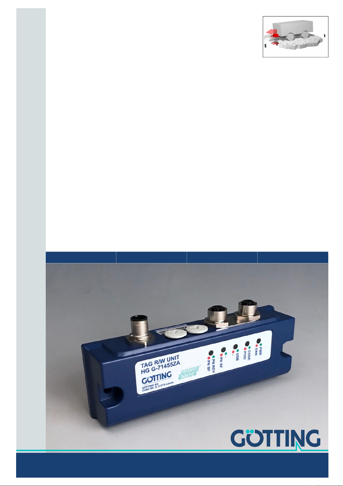
Device Description HG G-71450/1/3/5-A | English, Revision 02 | Date: 06.06.2019
4Table of Contents
4.3 Transponder Antenna ........................................................................................................24
4.3.1 Mounting Holes ...............................................................................................................25
4.3.2 Connection Cable ...........................................................................................................25
4.4 Interface HG 06150Y (optional for HG G-71450) ......................................................26
4.5 Commissioning ....................................................................................................................27
5 Interfaces: RS 232/serial (HG G-71450) ........................................28
5.1 Interface Parameter RS 232 ............................................................................................28
5.2 Telegram Setup ASCII Coding (SW5 = ON) ................................................................29
5.3 Telegram Setup of Binary Coding (SW5 = OFF) ........................................................30
5.4 Resetting the Antenna.......................................................................................................30
5.5 Transponder Programming ..............................................................................................30
5.6 Serial/parallel interface HG G-06150Y (optional)......................................................31
6 Interfaces: Profibus (HG G-71451).................................................32
6.1 Profibus Address (Hex Rotary Switch) .........................................................................32
6.2 Profibus Configurations ....................................................................................................32
6.3 Status and Command Bits ...............................................................................................33
6.4 Transponder Programming ..............................................................................................33
6.5 GSD File .................................................................................................................................34
7 Interfaces: CANopen® (HG G-71453) ............................................35
7.1 Definitions CAN and CANopen® ....................................................................................35
7.2 Node ID ..................................................................................................................................37
7.3 Default Values ......................................................................................................................37
7.4 Description of the Transmission Process Data Objects (TPDO) ...........................37
7.5 Description of the Receiving Process Data Objects (RPDO) .................................38
7.6 Heartbeat ...............................................................................................................................38
7.7 Description of the Service Data Objects (SDOs) .......................................................39
7.8 Object Directory ..................................................................................................................39
7.9 Manufacture Parameters - Node parameters.............................................................45
7.10 Transponder Programming ..............................................................................................46
7.11 EDS File..................................................................................................................................46
8 Interfaces: Profinet (HG G-71455) .................................................47
8.1 Input Bytes ............................................................................................................................47
8.2 Output Bytes.........................................................................................................................47
8.3 Status bits .............................................................................................................................48
8.4 Instruction bits .....................................................................................................................48
8.5 Transponder Programming ..............................................................................................48
8.6 GSDML File ...........................................................................................................................48
9 Software / Configuration ................................................................49
9.1 Connection to a PC.............................................................................................................49
9.1.1 Via the serial interface (HG G-71450 / HG G-71451 / HG G-
71453) ................................................................................................................................49
9.1.2 Via the USB interface (HG G-71455) ........................................................................50
9.2 Terminal Program ...............................................................................................................51
9.3 Logging (CSV Output)........................................................................................................51
9.4 Monitor Program (Service) ...............................................................................................52
9.4.1 Main Menu Monitor Program HG G-71450.............................................................53
9.4.2 Main Menu Monitor Program HG G-71451.............................................................53
9.4.3 Monitor Program HG G-71453 ...................................................................................54
9.4.3.1 Main menu....................................................................................................................54
9.4.3.2 (P)osi Filter ...................................................................................................................54
9.4.3.3 CAN Menu.....................................................................................................................55
9.4.4 Main Menu Monitor Program HG G-71455.............................................................56
9.5 Update of the Operating Software (Firmware) ..........................................................57
9.5.1 About the RS 232 interface (HG G-71450 / HG G-71451 / HG
G-71453) ...........................................................................................................................57
9.5.2 Via the USB Interface (HG G-71455) ........................................................................58
10 Transponder Programming ............................................................61