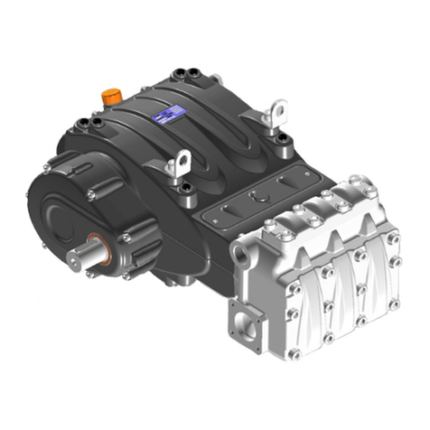
GP MK40A Operating instructions

MK
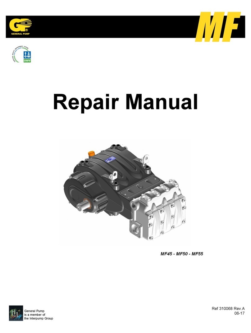
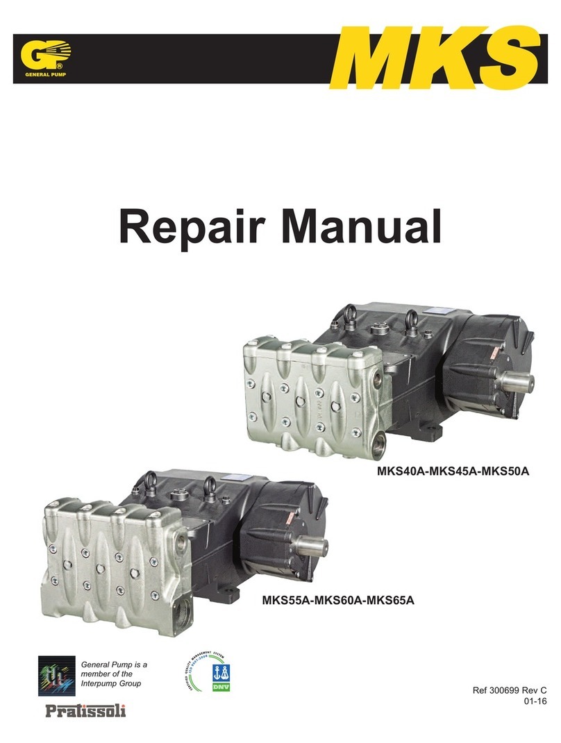
Repair Manual
General Pump is a
Member of
The Interpump Group
Ref 300679 Rev.F
03-20
MK40A-MK45A-MK50A
MK55A-MK60A-MK65A

GENERAL PUMP A member of the Interpump Group MK SERIES
Page 2
INDEX
1. INTRODUCTION ..................................................Page 3
2. REPAIR INSTRUCTIONS ...........................................Page 3
2.1 Crank Mechanism Repair. . . . . . . . . . . . . . . . . . . . . . . . . . . . . . . . . . . . . . . . . Page 3
2.1.1 Crank Mechanism Disassembly .............................Page 4
2.1.2 Crank Mechanism Assembly ...............................Page 13
2.1.3 Refurbishing the Crank Mechanism ..........................Page 23
2.2 Fluid End Repair ...............................................Page 24
2.2.1 Head Disassembly - Valve Units ............................Page 24
2.2.2 Head Assembly - Valve Units...............................Page 27
2.2.3 Disassembling the Plunger Unit - Supports - Seals ..............Page 33
2.2.4 Assembly of the Plunger Unit - Suports - Seals.................Page 36
2.2.5 Manifold Refurbishment ...................................Page 41
3. SCREW CALIBRATION ............................................Page 43
4. REPAIR TOOLS ..................................................Page 44
5. MAINTENANCE LOG ..............................................Page 45
Ref 300679 Rev.F
03-20

1. INTRODUCTION
This manual describes the instructions for Repairing MK Series pumps, and must be carefully read and
understood before performing any repair intervention on the pump. Correct use and adequate maintenance is
fundamental for the pump’s regular operation and long wear. General Pump declines any responsibility for
damage caused by the misuse or the non-observance of the instructions described in this manual.
2. REPAIR INSTRUCTIONS
2.1 Crank Mechanism Repair
Crank mechanism repair operations must be carried out after draining the oil from the crankcase. To drain
the oil, remove the oil refill cap 1, Fig. 1, and then the draining plug (2, fig. 1).
Exhausted oil must be collected in an appropriate receptacle and disposed of in
designated locations. In absolutely no case may it be disposed of in the environment.
MK SERIES
Page 3
GENERAL PUMP A member of the Interpump Group
Ref 300679 Rev.F
03-20

MK SERIES
Page 4
2.1.1 Crank Mechanism Disassembly
The correct sequence is the following
Completely drain the oil from the pump, then remove the key from the shaft (1, fig.2).
Unscrew the reducer flange fastening screws (1, fig. 3) and remove the flange from the shaft.
On the opposite side, unfasten the screws (1, fig. 4) and therefore remove the bearing cover.
GENERAL PUMP A member of the Interpump Group
Ref 300679 Rev.F
03-20

MK SERIES
Page 5
Unfasten the reducer cover screws (1, fig. 6).
Insert 3 dowels, or 3 M8 threaded screws (1, fig. 7) in the appropriate holes to aid extraction, and two
sufficiently long M10 screws in order to support the cover (2, fig. 7).
Disassemble the crankcase cover by unfastening the relevant screws (1, fig. 5).
GENERAL PUMP A member of the Interpump Group
Ref 300679 Rev.F
03-20

MK SERIES
Page 6
Screw on the 3 threaded screws (1, fig. 8) and simultaneously, using the appropriate tool (p/n 27516700),
hammer on the tool itself so that the bearing remains on the pinion when extracting the cover (1, fig. 9).
When this operation is complete, remove the reducer cover and then slip off the bearing from the pinion.
Remove the screws that fasten the ring gear stopper (1, fig. 10), and remove the stopper itself (1, fig. 11).
Remove the ring gear (1, fig. 12). If necessary, use a slide hammer applying it to the 2 M8 holes (2, fig. 12).
GENERAL PUMP A member of the Interpump Group
Ref 300679 Rev.F
03-20

MK SERIES
Page 7
Remove the pinion by using a slide hammer applying it to the M14 hole (1, fig. 14).
Lift the safety washer key (1, fig. 15)
Remove the key from the shaft (1, fig. 13).
GENERAL PUMP A member of the Interpump Group
Ref 300679 Rev.F
03-20

MK SERIES
Insert a spacer under the connecting rod to block shaft rotation (1, fig. 16).
Using an appropriate wrench, unscrew and remove the ring nut (1, fig. 17) and then remove the safety
washer (1, fig 18).
Screw a SKF KM19 type ring nut onto the pressure sleeve (1, fig. 19), then loosen the sleeve using an
appropriate wrench (1, fig. 20).
Page 8
GENERAL PUMP A member of the Interpump Group
Ref 300679 Rev.F
03-20

MK SERIES
Page 9
On the opposite side, unfasten the reducer case screws (1, fig. 21), and then remove the case (1, fig. 22).
Unscrew the connecting rod screws (1, fig. 23).
Disassemble the connecting rod caps with the split bearings; be particularly aware of disassembly order.
The connecting rod caps and the related connecting rods must be reassembled in the
exact order and coupling as during disassembly.
To avoid error, caps and connecting rods are numbered on one side (1, fig. 24).
GENERAL PUMP A member of the Interpump Group
Ref 300679 Rev.F
03-20

MK SERIES
Page 10
Remove the pressure sleeve (1, fig. 26).
Remove the upper split bearing of the connecting rods (1, fig. 27).
Push the connecting rods forward in the direction of the hydraulic side in order to push out the crankshaft.
Use the appropriate tool (p/n 27566200) to facilitate this operation (1, fig. 25)
GENERAL PUMP A member of the Interpump Group
Ref 300679 Rev.F
03-20

MK SERIES
Remove the crankshaft with the help of a hammer on the PTO side (1, fig. 28). Remove the shaft and the
bearing (1, fig. 29).
If the replacement of one or more connecting rods or plunger guides is necessary, please operate as follows:
Unfasten the screws of the tool (p/n 27566200 to unlock the connecting rods (1, fig. 31) and therefore
extract the connecting rod-plunger guide units from the opening behind the crankcase (1, fig. 32).
On the opposite side, extract the bearing (1, fig. 30)
Page 11
GENERAL PUMP A member of the Interpump Group
Ref 300679 Rev.F
03-20

MK SERIES
Couple the connecting rods with the previously disassembled caps; be sure to respect numbering (1, fig. 33).
Remove the pin (1, fig. 35) and then remove the connecting rod (1, fig. 36).
Remove the two seeger rings that block the plunger pin by using the appropriate tool (1, fig. 34).
Page 12
GENERAL PUMP A member of the Interpump Group
Ref 300679 Rev.F
03-20

MK SERIES
To separate the rod from the plunger guide, unfasten the M10 hexagonal-head screws using a size 17 socket
wrench (1, fig. 37).
2.1.2 Crank Mechanism Assembly
Proceed with assembly by inverting the precedure indicated in paragraph 2.1.1.
The correct sequence is the following:
Connect the rod to the plunger guide
Insert the Ø5 pin in the appropriate hole on the plunger guide (1, fig. 38) and connect the rod to the plunger
guide using M10 x 35 screws (1, fig. 39).
Page 13
GENERAL PUMP A member of the Interpump Group
Ref 300679 Rev.F
03-20

MK SERIES
Block the rod using a clamp, and proceed with calibration using a torque wrench (1, fig. 40) as indicated
in paragraph 3. “SCREW CALIBRATION”
Insert the connecting rod in the plunger guide (1, fig. 36) and then insert the pin (1, fig. 35). Apply the
two seeger rings using the correct tool (1, fig. 34).
Make sure that conrods, plunger guides and wrist pins can move freely after being
assembled.
Separate the caps from the connecting rod; correct coupling is guaranteed by the numbering on the side
(1, fig. 33).
After verifying the perfect cleaning of the crankcase, insert the connecting rod-plunger guide unit inside the
cylinders of the crankcase (1, fig. 32).
The insertion of the connecting rod-plunger guide unit inside crankcase must be done
by positioning the connecting rods with the numbering visible from above.
Block the three units using the correct tool, p/n 27566200(1, fig 31).
Pre-assemble the bearing, PTO side, on the shaft (1, fig. 41) and assemble the bearing on the opposite
side on the crankcase (1, fig. 42).
The bearing in fig. 42 has a tapered internal ring. Verify that the taper goes from the
outside towards the inside in order to allow the subsequent insertion of the sleeve.
Page 14
GENERAL PUMP A member of the Interpump Group
Ref 300679 Rev.F
03-20

MK SERIES
Insert the shaft (1, fig. 29) until the pre-assembled bearing is aligned with the edge of the crankcase
(1, fig. 43).
Manually insert the pressure sleeve to maintain the shaft alignment (1, fig. 44).
Assemble the reducer case (1, fig. 45) and the related gasket (2, fig 45) using the 6 M12 x 40 screws
(1, fig. 46), the 2 M12 x 50 screws (1, fig. 47) and the Ø 12 Grower washers (2, fig. 46 and fig. 47).
Calibrate the screws with a torque wrench (1, fig. 48) as indicated in paragraph 3. “SCREW CALIBRATION”
Page 15
GENERAL PUMP A member of the Interpump Group
Ref 300679 Rev.F
03-20

MK SERIES
Page 16
Completely insert the pressure sleeve on the shaft from the opposite side of the PTO (1, fig. 49 and fig. 50).
Pressure sleeve insertion must be done without oil or lubricants.
Insert the sleeve until the external surface (tapered) couples perfectly with the inside of the
bearing. During insertion, be sure that the bearing remains in contact with the shaft shoulder.
Measure the dimension “X” indicated in fig. 51.
GENERAL PUMP A member of the Interpump Group
Ref 300679 Rev.F
03-20

MK SERIES
Page 17
Screw the ring nut and fasten the sleeve until the dimension “X” is reduced by a value ranging between 0.7
and 0.8 mm (fig. 52).
Unscrew the ring nut, insert the safety washer (1, fig. 53) and completely screw the ring nut (1, fig. 54);
then fold the washer’s locking key (1, fig. 55).
GENERAL PUMP A member of the Interpump Group
Ref 300679 Rev.F
03-20

MK SERIES
Page 18
Remove the device that blocks the connecting rods using p/n 27566200 (1, fig. 31).
Insert the upper split bearings between the connecting rods and the shaft (1, fig. 56)
In order to correctly assemble the split bearings, be sure that the split bearings’
reference key in the appropriate seat on the connecting rod (1, fig. 57).
Apply the lower split bearings to the caps, (1, fig. 58) being sure that the split bearings’ reference key is
positioned in the appropriate seat on the cap (1, fig. 58).
Fasten the caps to the connecting rods using the M12 x 1.25 x 87 screws (1, fig. 59).
Pay attention to the correct assembly of the caps. the numbering must face upwards.
Tighten the screws with a torque wrench set as indicated in the SCREW CALIBRATION chart of paragrapg 3.
The conrod screws should be tightened at intermediate incremental values.
GENERAL PUMP A member of the Interpump Group
Ref 300679 Rev.F
03-20

MK SERIES
Page 19
Reassemble the bearing on the pinion (1, fig. 60) and fully insert the pinion in the seat on the reducercase (1,
fig. 61) by using a hammer.
Apply the 22 x 14 x 100 key in the seat on the shaft (1, fig. 62) and insert the ring gear on the shaft.
Fasten the ring gear stopper (1, fig. 63) using the 2 M10 x 25 screws (2, fig. 63).
Calibrate the screws with the torque wrench as indicated in paragraph 3. “SCREW CALIBRATION”
GENERAL PUMP A member of the Interpump Group
Once tightened on the crankshaft, make sure that conrods still have axial right-left endplay.
Ref 300679 Rev.F
03-20

MK SERIES
Page 20
Assemble the bearing on the reducer cover (1, fig. 66).
Assemble the reducer cover (1, fig. 67) and fasten it using 8 M10 x 50 screws (1, fig. 68). Use a
stopper to avoid the bearing coming out of the seat (1, fig. 69).
Calibrate the screws with the torque wrench as indicated in paragraph 3. “SCREW CALIBRATION”
Apply the 3 Ø 12 x 40 pins to the reducer case (1, fig. 64) and insert the gasket (1, fig. 65).
GENERAL PUMP A member of the Interpump Group
Ref 300679 Rev.F
03-20
This manual suits for next models
6
Table of contents
Other GP Water Pump manuals
Popular Water Pump manuals by other brands
GE
GE Druck PV210 operating instructions
Viking pump
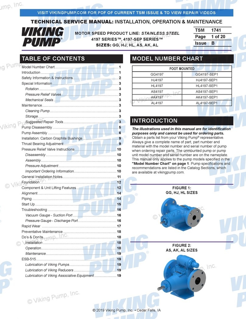
Viking pump 4197 Series Technical & service manual

FMC
FMC M12-HD Operation & maintenance manual
Graco
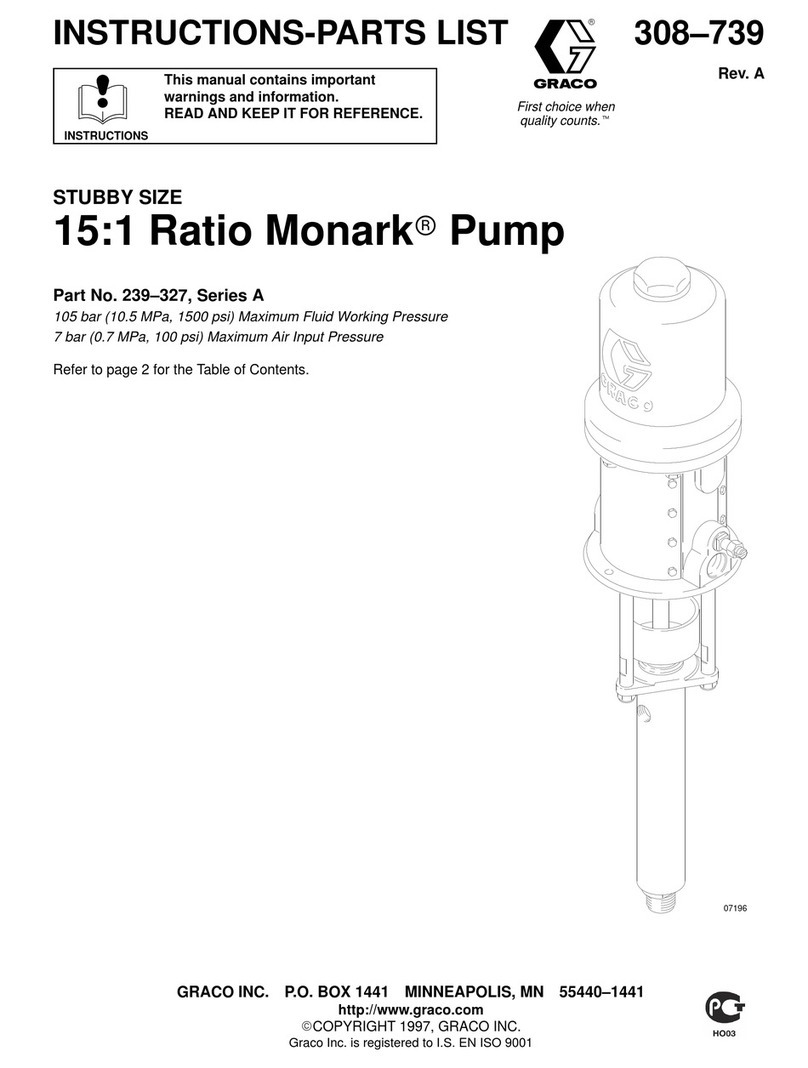
Graco Monark A Series Instructions-parts list

Pentair
Pentair S316 Owner's/operator's manual

Ingersoll-Rand
Ingersoll-Rand ARO 666250 C Series Operator's manual
Graco
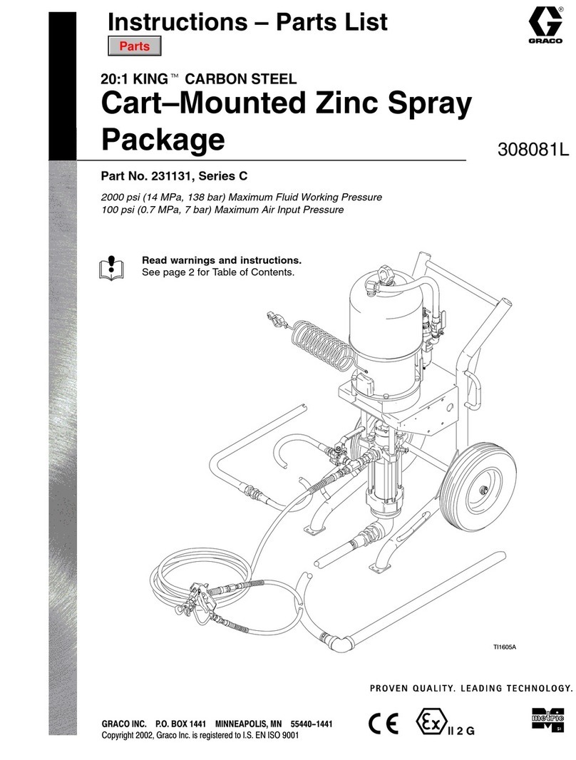
Graco 20:1 KING 231131 Instructions-parts list

Standard Pump
Standard Pump SPSG15 Series Instructions and parts list
WilTec
WilTec 50723 Short manual

PSG Dover
PSG Dover WILDEN A1 Accu-Flo Engineering, operation & maintenance
Xtreme Power
Xtreme Power 76045 Owner's manual and safety instructions

IWAKI PUMPS
IWAKI PUMPS MDF-L instruction manual
