Page 20
GENERAL PUMP A member of the Interpump Group
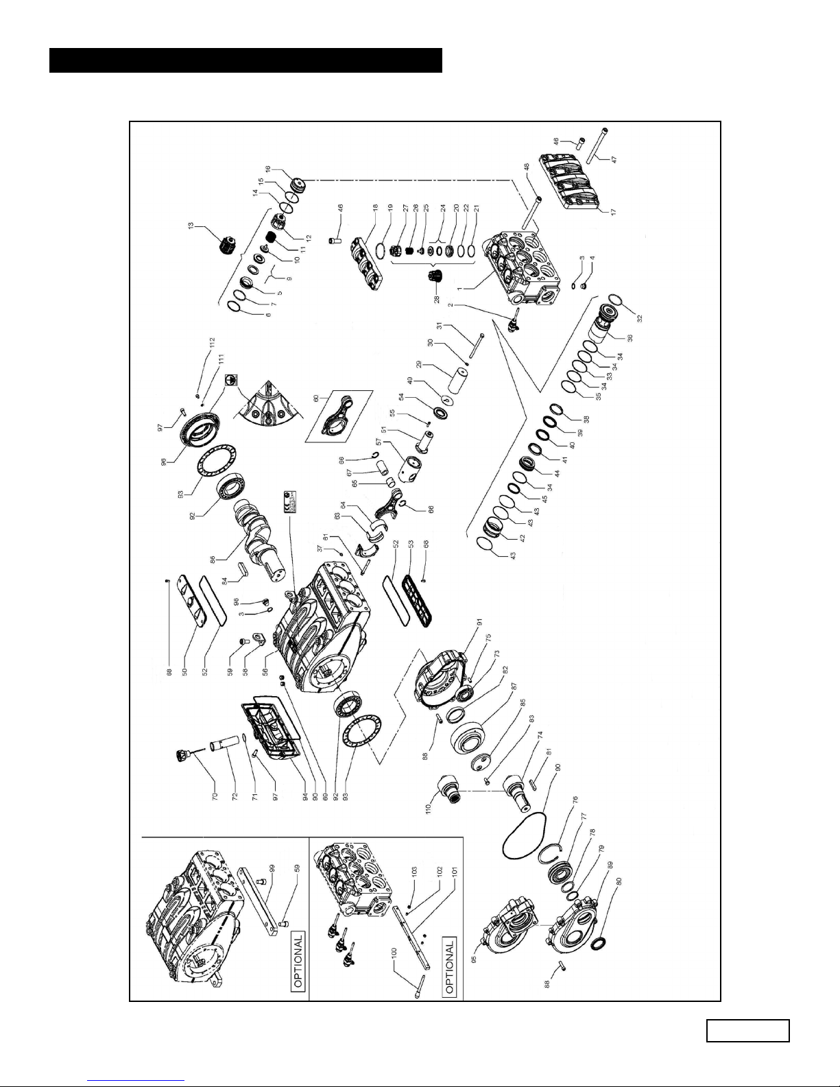
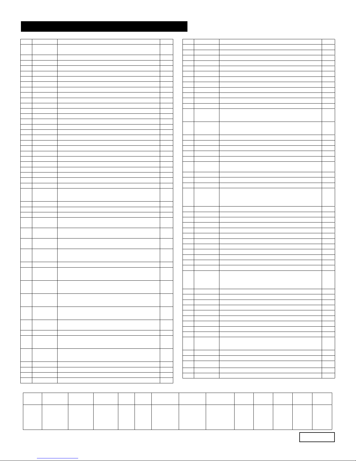
MF45/50/55 SERIES
REPAIR KITS
Item Part # Description QTY.
50 F73150022 CLOSED INSPECTION COVER 1
51 F73050636 PLUNGER GUIDE ROD 3
52 F90414800 OR Ø 202.8X3.53 2
53 F73150122 OPEN ISPECTION COVER 1
54 F90168500 RAD. RING Ø 40.0X72.0X7.0/8.5 3
55 F99188400 SCREW M6X20 12
56 F73010213 PUMP CASING 1
57 F79050443 PLUNGER GUIDE 3
58 F73210674 LIFTING BRACKET 2
59 F99513000 SCREW M16X30 4
60 F73030301 CONNECTING ROD ASSY. 3
61 F99378800 CONNECTING ROD SCREW 6
63
F90928300
F90928100
F90928200
CONROD HEAD SEMI-BUSHING LOWER - INF
CONROD HEAD SEMI-BUSHING LOWER +0.25
CONROD HEAD SEMI-BUSHING LOWER +0.50
3
64
F90928000
F90928400
F90958500
CONROD HEAD SEMI-BUSHING UPPER - INF
CONROD HEAD SEMI-BUSHING UPPER +0.25
CONROD HEAD SEMI-BUSHING UPPER +0.50
3
65 F90917300 CONROD BUSHING 3
66 F90069700 STOP RING Ø 35 6
67 F97745000 SPINDLE 3
68 99183700 SCREW M6X14 4
69 98206000 HOLE PLUG Ø 15 6
70 F98233500
F98233600
OIL FILLING PLUG G1”
OIL FILLING PLUG G1” - ATEX 1
71 90361600 OR Ø 34.65X1.78 1
72 F73210295 TUBE FOR OIL FILLING PLUG, G1” 1
73 F91854000 CY. ROLLER BEARING 1
74
F10076735
F10076835
F10076935
F10082255
PINION, Z24 Ø 1.875, HELICOL
PINION, Z21 Ø 2.238, HELICOL
PINION, Z18 Ø 2.722, HELICOL
PINION, Z19 Ø 3.211, HELICOL
1
75 F97623000 TMP. CYL PIN. Ø 10.0X24.0 2
76 F90101000 STOP RING Ø 120 1
77 F91859900 ADJUST. ROLLER BEARING 1
78 F73210455 BEARING SUPPORT RING 1
79 F90081000 STOP RING Ø 55 1
80 F90172400 RAD. RING, Ø 55.0X75.0X8.0, VITON 1
81 F91500500 TAB, 14.0X9.0X60.0 1
82 F73210589 RING GEAR SUPPORT RING 1
83 9936700 SCREW M10X25 2
84 F91511000 TAB, 22.0X14.0X80.0 1
85 F74213255 RING GEAR STOP 1
86 F73020035 CRANKSHAFT C.70 1
87
F10077035
F10077135
F10077235
F10082355
RING GEAR, Z46 R.1.875 HELICAL
RING GEAR, Z47 R.2.238 HELICAL
RING GEAR, Z49 R.2.722 HELICAL
RING GEAR, Z61 R.3.211 HELICAL
1
88 F99371000 SCREW M10X40 15
89 F73210113 REDUCTION GEAR COVER 1
90 F90415000 OR, Ø 253.6X3.53 2
91 F73210013 REDUCTION GEAR BOX 1
92 F91881000 CY. ROLLER BEARING 2
93 F73210384 SIDE SEAL 2
94 F73160022 CASING COVER 1
96 F73150222 BEARING COVER 1
97 F99368600 SCREW M10X30 14
98
F98218700
F98218700
F98208150
PLUG G1/2”X10
PLUG G1/2”X10 - ATEX
PLUG G1/2”X13 - ATEX
2
1
1
99 F73200064 FOOT 2
100 F94540000 LEVER M8X107 1
101 F73215864 VALVE LIFTER BRACKET 1
102 F99301800 SCREW M8X10 2
103 F92221800 SCREW M8X1.5X5X13 2
Item Part # Description QTY.
1F73121115
F73121215
MANIFOLD (45-50)
MANIFOLD (55) 1
2 F10755401 VALVE OPENING DEVICE 3
3 96751400 WASHER Ø 21.5X27X1.5 5
4 F98218500 STEEL PLUG 3
5 F36206666 INLET VALVE HOUSING 3
6 F90527000 ANTI-EXTRUSION RING, Ø 61.2X67X2 3
7 F90410500 OR Ø59.62X3.53 3
9 F36208701 BALL VAVLE ASSY. 3
10 F36208951 INTERNAL VALVE GUIDE 3
11 F94769800 SPRING, Ø 41.5X37.9
3
12 F36206005 INLET VALVE GUIDE 3
13 F36715001 INLET VALVE UNIT 3
14 F90391100 OR Ø 66.35X2.62 3
15 F90528200 ANTI-EXTRUSION RING, Ø 68.0X72.0X1.5 3
16 F73221556 INLET VALVE PLUG 3
17 F73221415 INLET VALVE COVER 1
18 F73210915 OUTLET VALVE COVER 1
19 F90412000 OR, Ø 68.28X3.53 3
20 F36206766 OUTLET VALVE HOUSING 3
21 F90526000 ANTI-EXTRUSION RING Ø 51.5X56.0X1.5 3
22 F90389000 OR Ø 50.47X2.62 3
24 F36208801 BALL VALVE ASSY. 3
25 F36206766 INTERNAL VALVE GUIDE 3
26 F94760500 SPRING Ø28.5X32 3
27 F36206105 OUTLET VALVE GUIDE 3
28 F36207701 OUTLET VALVE UNIT 3
29
F73040309
F73040409
F73040509
PLUNGER Ø 45X117
PLUNGER Ø 50X117
PLUNGER Ø 55X117
3
30 F96710500 WASHER , Ø 10.0X18.0X0.9 3
31 F99383000 SCREW M10X140 3
32 F90411500 OR Ø 63.5X3.53 3
33 F90528550
F90527000
ANTI-EXTRUSION RING, Ø 72.9X77.0X1.5 (MF45-50)
ANTI-EXTRUSION RING, Ø 79.8X80.0X1.5 (MF55) 3
34 F90391400
F90391350
OR, Ø 72.69X2.62 (MF55)
OR, Ø 71.12X2.62 (MF45-50) 12
35 F90528650
F90528400
ANTI-EXTRUSION RING, Ø 74.9X79.0X1.5 (MF55)
ANTI-EXTRUSION RING, Ø 71.9X76.8X1.5 3
36
F73221856
F73221956
F73222056
CYLINDER SEAL Ø 45
CYLINDER SEAL Ø 50
CYLINDER SEAL Ø 55
3
37 701111 OR, Ø 10.78X2.62 6
38
F74100192
F74100292
F74100392
PISTON HEAD RING, Ø 45
PISTON HEAD RING, Ø 50
PISTON HEAD RING, Ø 55
3
39
90285000
F90286300
F90287300
SEAL RING, Ø 45.0X60.0X4.5/7.5 HP
SEAL RING, Ø 50.0X65.0X7.5/4.5 HP
SEAL RING, Ø 55.0X70.0X5.0/4.5 HP
3
40
F90284800
F90286500
F90287500
RESTOP RING, Ø 45
RESTOP RING, Ø 50
RESTOP RING, Ø 55
3
41
F73222170
F73222270
F73222370
CENTERING RING Ø 45
CENTERING RING Ø 50
CENTERING RING Ø 55
3
42 F73221691
F73221791
CENTERING HEAD BUSHING Ø 45-50
CENTERING HEAD BUSHING Ø 55 3
43 F90371000 OR, Ø 81.0X2.0 9
44
F73080056
F73080156
F73080256
BOTTOM RING Ø 45
BOTTOM RING Ø 50
BOTTOM RING Ø 55
3
45
F90284600
F90286000
F90287000
SEAL RING, Ø 45.0X53.0X5.5 LP
SEAL RING, Ø 50.0X58.0X5.5 LP
SEAL RING. Ø 55.0X63.0X5.5 LP
3
46 F99514200 SCREW M16X45 14
47 F99522500 SCREW M16X200 6
48 F99522200 SCREW M16X180 2
49 F96735500 WASHER Ø 16.0X65.0X1.0 3
KIT
NUMBER
F2312 (MF45)
Plunger Pack.
F2313 (MF50)
Plunger Pack.
F2314 (MF55)
Plunger Pack.
F2142
Inlet
Valve
F2062
Outlet
Valve
F2315 (MF45)
Complete Seals
F2316 (MF50)
Complete Seals
F2317 (MF55)
Complete Seals
F2150
Conn. Rod
F2151
Conn. Rod
F2153
Conn. Rod
F2152
Mounting
Feet
F2189
Valve lifter
junction
Positions
Included
32, 33, 34,
35, 37, 39, 40,
43, 45
32, 33, 34,
35, 37, 39, 40,
43, 45
32, 33, 34,
35, 37, 39, 40,
43, 45
13 28
6, 7, 14, 15,
19, 21, 22, 32,
33, 34, 35, 37,
39, 40, 43, 45,
52, 54, 71, 80,
90, 93
6, 7, 14, 15,
19, 21, 22, 32,
33, 34, 35, 37,
39, 40, 43, 45,
52, 54, 71, 80,
90, 93
6, 7, 14, 15,
19, 21, 22, 32,
33, 34, 35, 37,
39, 40, 43, 45,
52, 54, 71, 80,
90, 93
63, 64 63, 64 63, 64 59, 99 101, 102,
103
Ref 310069 Rev. B
07-18