4
Planering / Planning / Planung
(mm)
Mycket Viktigt!
Kontrollera väggens före installation.
Max belastning på lyftenhet är 100 kg och egenvikt upp mot 100 kg.
Säkerställ att väggen klarar den koncentrerade belastning som uppkommer under motorenheter.
Säkerställ att motorenheterna kan xeras i väggen och att konstruktionen ej är porös.
I vissa fall kan väggen behöva förstärkas och anpassas för att motorenheter skall kunna xeras tillfredsställande.
Placera aldrig lyftaren så att klämrisker uppstår mot annan fast inredning.
Om lyftaren placeras mot en slät vägg ska springan inte understiga 5mm och inte överstiga 8 mm.
Very Important!
Check oor stability before installation.
Maximum load on lifting unit is 100kg and dead load up to 100kg.
Ensure that the wall can withstand the concentrated load that occurs under motor units.
Make sure that the engine units can be xed to the wall and that the structure is not porous.
In some cases, the wall may need to be reinforced and adapted in order for engine units to be adequately xed.
Never place the lift so that there is a risk of crushing against other solid interior ttings.
If the lift is placed in front of a at wall, the gap should not be below 5mm or exceed 8mm.
Sehr wichtig!
Prüfen Sie vor der Montage die Tragfähigkeit des Bodens.
Die max. Belastung des Lifts beträgt 100 kg, bei einem Eigengewicht von bis zu 100 kg.
Stellen Sie sicher, das der Boden unter den Hubsäulen den auftretenden konzentrierten Lasten standhält.
Stellen Sie sicher, das der Lift am Boden an der Wand befestigt werden kann und dass die Bodenkonstruktion nicht porös ist.
In einigen Fällen, muss die Boden möglicherweise verstärkt bzw. angepasst werden, damit der Lift ordnungsgemäß befestigt
werden kann.
Platzieren Sie den Centerlift 960 so, das Klemmgefahren an angrenzenden Möbeln oder Einrichtungen ausgeschlossen
werden. Steht der Lift an einer Wand, so sollte der Abstand der Arbeitsplatte zur Wand 5-8 mm betragen.
SE
EN
DE
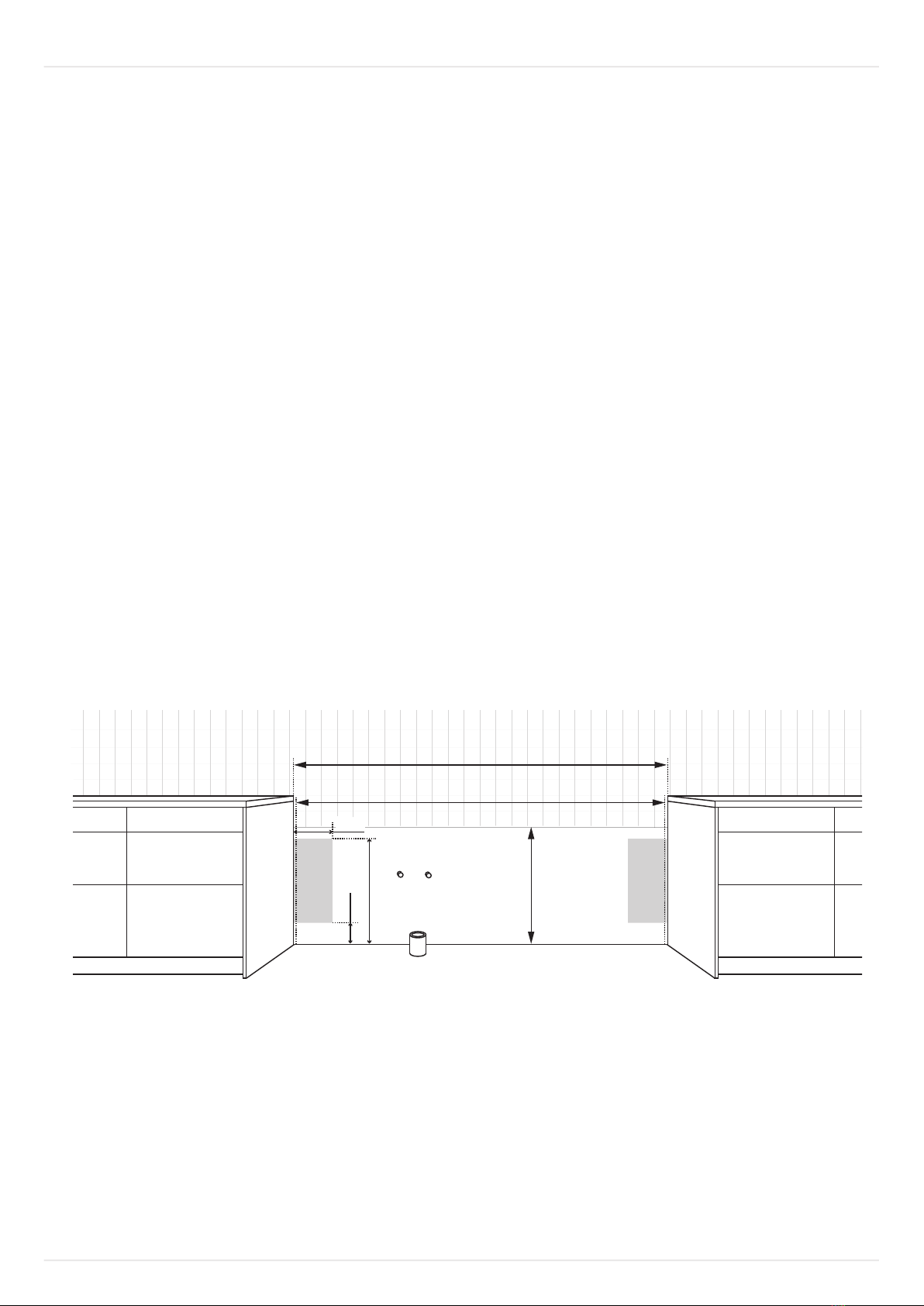
L
0 / 700
100
190
570
Example:
L = 1900mm
W = 1900 + 10 = 1910mm
* = Greater than 300mm aects the ow of wastewater
L + 10mm
Kakel / Flis / Tile / Fliese / Faïence