2
4. Product Features
1/4” CMOS SXGA Sensor (1.3MegaPixel)
IP66 Waterproof housing for outdoor use.
Automatically removable IR-cut filter for day and night function
Built-in 24 infrared LEDs illuminate objects up to a distance of 10m
View Angle: Diagonal: 89 Degree / Horizontal: 71 Degree / Vertical: 49.5 Degree.
High Resolution Image Processor (160x120/ 320x240/ 640x480/ 1280x1024).
High Performance Image Compression.
Compatible with Windows 7/ Vista/ XP (32bit & 64bit) and Linux OS.
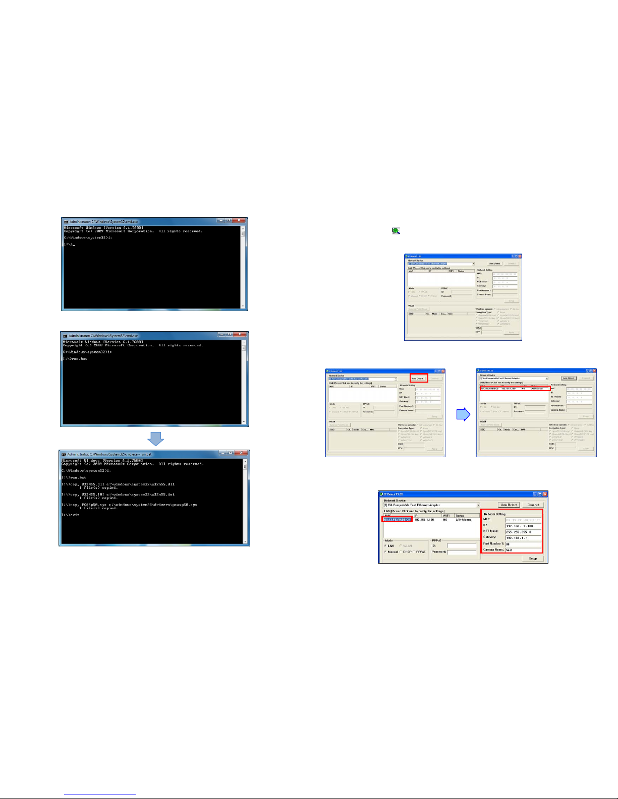
The provided IP Detect tool allows you to quickly search for and set up cameras located in the local
area network (supports Windows 7/ Vista/ XP.
Supports Safari/ Internet Explorer/ Firefox browser for remote viewing on PC or iPhone.
Supports Motion detected Mail Function
Supports digital zoom in function.
LAN connector: RJ45 port to connect to 10/ 100Mbps Ethernet
Supports TCP/IP / HTTP / FTP / SMTP / DHCP / PPPoE / DDNS / UPnP / NTP service
Multi-Languages OSD: English / French / Portuguese / German / Italian / Netherland / Spanish/
Russian / Japanese / Traditional Chinese
Bundle Surveillance Software:
-Video File Management: Video file database and playback control.
-Storage Recyclable: When running out of disk space, files with the earliest date will be
overwrite automatically.
-Motion Detection: Detect any movement in the mask area and invoke the alarm as soon as
movement is detected.
-Supports up to 16 cameras remote view and record simultaneously.
NOTE: When remote view and record 16 cameras simultaneously, a system with higher
CPU performance is recommend
-Multi-Languages OSD: English/ French/ German/ Italian/ Dutch/ Spanish/ Russian/
Japanese/ Traditional Chinese.
-Supports scheduled recording function.
3
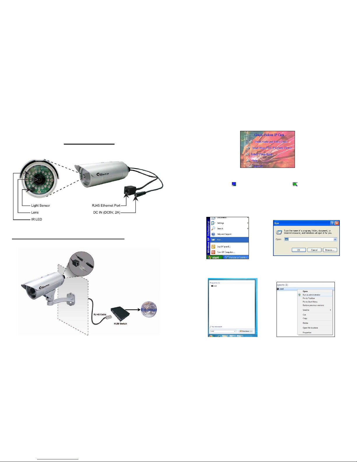
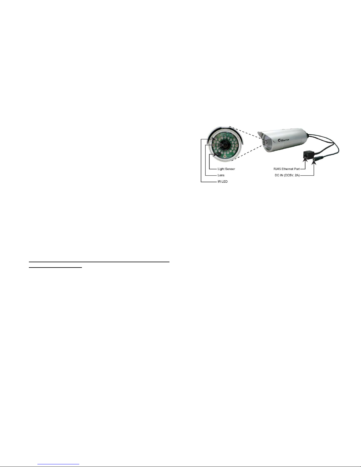
5. Hardware Overview
DC Input: Connects to the power adapter. (DC5V, 2A)
RJ-45 Ethernet Connector: For connects to 10Base-T Ethernet cabling or 100Base-TX Fast
Ethernet cabling.