Green Panther GP-4019BP-P User manual

Note: Please read the following instructions before use. This book contains important information on SAFETY, ASSEMBLY, OPERATION
& DISCLAIMER: DUE TO CONSTANT UPGRADATION, FEATURES AND SPECIFICATIONS ARE SUBJECT TO CHANGE WITHOUT NOTICE
GP-4019BP-P
BRUSH CUTTER BACK PACK
USER MANUAL

2
GENERAL INSTRUCTIONS FOR SAFETY OPERATION
All our company products are delivered with an Owner’s manual. Please read it carefully to get
acquainted with the operation of your unit. For further details, consult your dealer.
Before Operation
Protect head (eyes and ears), feet and hands with safety hat, ear cover, goggles, safety shoes
and protective clothes.
Dress properly, do not wear loose clothing or jewelry that could become caught in moving parts
of the unit.
Never let a child operate the machine.
Be sure to check bolts and other fasteners to see if any of them have become loose or missing.
Cutting blade
- The cutter blade is very sharp, handle it with care.
- To install the blade correctly, read the instructions in this manual thoroughly.
- The Cutter fixing blot is left threaded, turn counter-clockwise to tighten, clockwise to loosen.
Fuel
NEVER OPERATE THE ENGINE WITH GASOLINE ONLY.
The engine requires a fuel mix of 25 parts regular gasoline to I part quality two- cycle oil
Do not fill the fuel tank while the engine is running or still warm. The fuel should be poured into
the fuel tank when the engine is cold.
Do NOT SMOKE WHEN FUEL IS ADDED, and when you are working with the machine.
Keep an open flame away becaruse fuel vapors are flammable.
Never smoke or allow a flame to come close to the unit while mixing fuel, filling the tank or
maintaining the unit.
Fuel should be stored in a dry and cool place.
During Operation
The unit should be operated in a well wentilated area.
Keep children away.Onlookers should be kept at a safe distance from the work area, at least 7 -
8m(30 feet).
Keep all parts of your body and clothing away from the blade when starting or running the
engine.
While cutting, hold the machine firmly with both hands, and stand with feet well-balanced and
your body balanced.

3
GENERAL INSTRUCTIONS FOR SAFETY OPERATION
The operator must obey the local regulations of cutting area.
Never carry the unit with the engine running.
For safety, the unit should not run in full throttle without any load.
Don’t run the unit without a muffier.
During a heavy work, be always with a partner.
When making a repair or adjustment, the unit must be stopped and the fuel completely drained.
For Long-term Storange
Drain all fuel from the carburetor, fuel tank and fuel lines.
Repair any damage which has resulted from use.
Clean the unit with a clean rag, or the use of high pressure air hose.
Put a few drops of engine oil into the cylinder through the spark plug hole, and spin the engine
over several times to distribute oil, then reinstall the spark plug.
Cover the unit and store it in a dry area.
Brush Cutter is composed of three major units;engine, flexible shaft and drive shaft.
1. Assembling drive shaft (Fig. I)
Insert the flexible shaft into the joint pipe of Drive Shaft to the end and tighten the joint pipe bolt
by engaging the bolt to the slot of flexible shaft.
NOTE:Make sure to align square end of flexible inner shaft with square hole of drive shaft by
slightly rotating drie shaft. So that they arc connected firmly.
2. Assembling flexible shaft (Fig.2)
Remove temporarily installed PIN. Insert flexible shaft into clutch case to the end by inserting
square end of flexible inner shaft into square hole of adaptor m Clutch Case. Then screw-in the
PIN by engaging the pin the slot of flexible shaft.

4
3.Throttle cable and stop cord
Put throttle cable and stop cord through cable passage of shaft grip,then connect each terminal
with each proper position respcctively.(Fig.3)
Finally,clamp those connected throttle cable and stop cord together to flexblc shaft with two wire
clamp bands provided.(Fig.4)
4. Haldle (Fig.5)
Remove the handle bracket A.
Set the handle on, and attach the handle bracket A with two bolts slightly. And adjust position of
the handle according to your working style. Then fix it firmly with the bolts.
5. Safety cover(Fig.6)
1) Install the safety cover on the shaft with the safety cover bracket and the screws proivded.
2) Tighten the rcrews after setting the safety cover bracket at the appropriate position.

5
6. Blade
I) When installing a steel blade, fit the blade as shown in the fig. 7
2) When installing or removing a blade, lock cutter holder with lock handle to tighten or to
untighten
as shown in Fig. 8
NOTE: As the blade fixing bolt is left threaded, tum it counter-clockwise and take a special care
not to hurt your fingers by the blade. Be sure to check if it has been fitted correctly.
Adjust shoulder belt length as you feel appropriate before starting engine.
I. Filling the fuel (Fig.9)
1) This engine uses a fuel mix of 25 parts regular gasoline to I part of two-cycle oil. The fuel
should be premixed prior to pouring into the fuel tank. It is recommended a quality twocycle oil
be used in the fuel mix.
CAUTION:FAILURE TO MIX OIL WITH GASOLINE WILL RESULT IN SEIZURE
AND SEVERE DAMAGE TO THE ENGTNE.
2) Be sure to check bolts and other fasteners to see if any of them have become loose or missing.
OPERATING PROCEDURES

6
2. Starting
I) Open the fuel cock. (Fig. I 0)
2) Move the throttle lever to start position or about I /4 full throttle, in case of metal lever.
(Fig. II)
NOTE: Staring with full throttle causes sudden high revolution of Blade, which is dangerous,
so please avoid it.
3) Set the choKe lever to CLOSE. (Fig. 12)
4) Pull the recoil starter briskly, TAKING CARE TO KEEP THE HANDLE in your grasp, while not
allowing it to snap back.
5) When you hear con:bustible sounds a couple of times, move the choke lever back to as it is
(open position). Then pull the recoil starter briskly.
6) After starting the engine,allow it about 2-3 minutes to warm up before subjecting it to any load.
CAUTION : Biade may turn and flexible shaft may swing as engine starts. Do not let the
blade touch any object when engine starts.
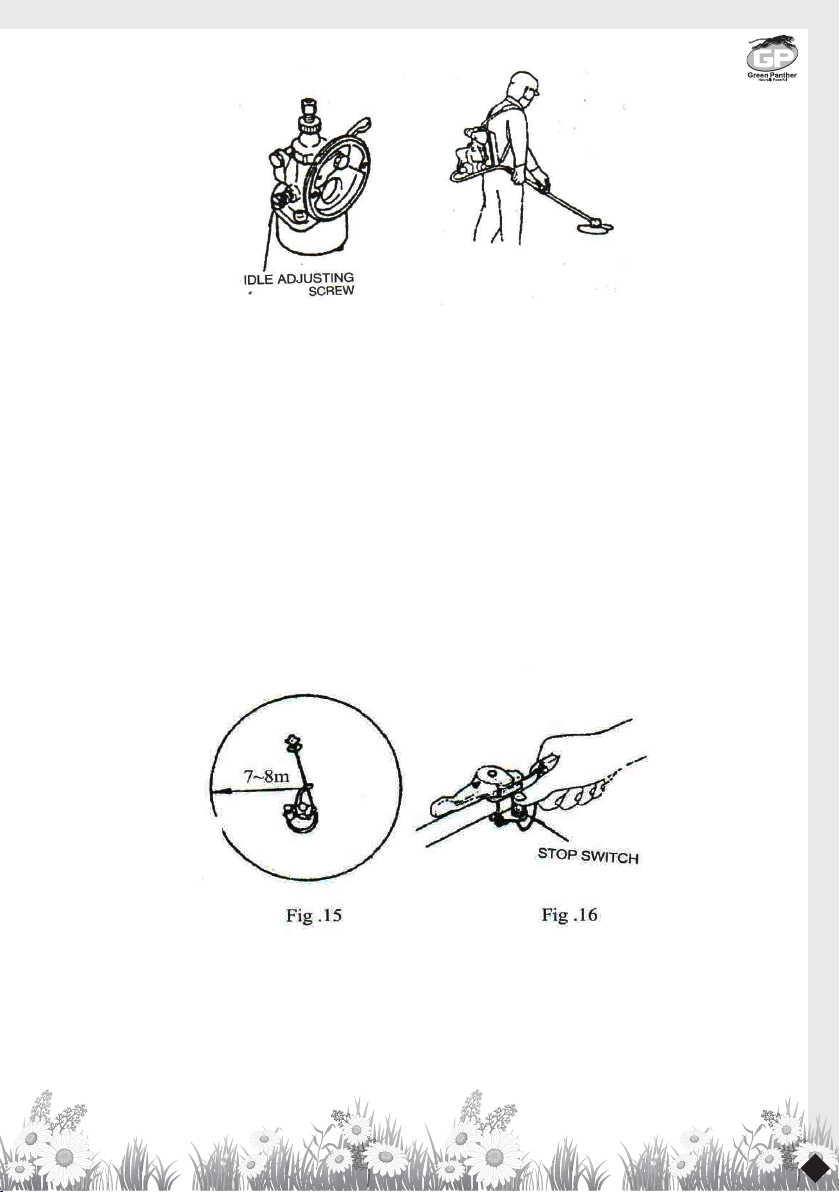
* Adjustment (Fig. 13)
When the idle speed is too high or too low,adjust it with the idle speed adjusting screw.
In case that the blade keeps turning at the idling speed, turn the idle adjusting screw
counterclockwise.
3. Ilow to carry (Fig.l4)
I) First, hold the handle with your left hand and bend yourself down. Slip your right arm into the
right belt.
2) Transfer the shaft to your right hand and reaching back,slip the left arm through the other belt.
3) When the engine unit is mounted on your back, grip the shaft as shown in the figure.

7
4. Cutting
I) The blade turns counterclockwise, therefore be advised to operate the cutter from right to
leftward for efficient cutting.
2) When working on a slope,the blade should allow the contour from top to bottom, with the
operator looking down to the left.
3) Keep the onlookers out of the working area at least 7~8m (30ft). (Fig. IS)
4) Special care
If the cutter should strike against stones or the like, stop the engine and cutter and make sure that
the cutter and related parts are in normal condition.
When grass or vine twines round the cutter, stop the engine and blade and remove grass or vine.
5. Stopping
1) Decrease the engine speed, and depress the stop button until engine has stopped. (Fig. 16)

8
3. I. Periodical check
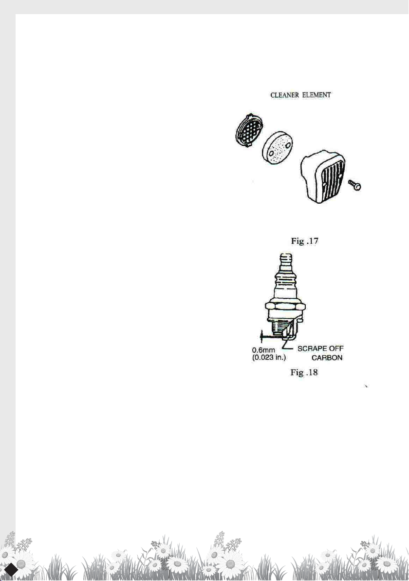
l) Cleaning
l - l Clean the cleaner element. (Fig. 17) I - 2 Scrape
off the carbon from the spark plug gap (standard
gap is 0.6mm or 0. 023in. ). (Fig. 18) 1 - 3 Clean the
cylinder exhaust port and muffler.
Remove the grasses or dusts entered in the
cylinder cover or fan case cover (otherhwise they
may cause a trouble such as an overheating).
2) Inspect carefully for any fuel or oil leaks.
3) Check all nuts, bolts, screws, etc., making sure
they are tightened and secured as they should be.
4) Lubricate Gear Case, every 50 hours of use.
5) When lubrichting flexible shaft, apply grease
in the flexible pipe of clutch case side. (It is
recommended to apply grease after every 10 hous
of use.)
2.Storage
I) Completely drain the fuel out of the tand and the
carburetor.
2) Keep the engine always to be highter than gear
box part.
3) Clean the unit carefully and keep it from
moisture.
Before installation,putthrottle,cable and stop cord
through cable passage of the shaft grip.
I) The throttle lever and stop switch are temperially assembled together. so they should be
disassembled first.
2) Put the round head of throttle cable and throttle cable together into the handle channel.
3) Fix the throttle lever on the hard shaft.
4) Finally,fix the stop switch on the throttle lever with a screw.
MAINTENANCE

9
SPECIFICATIONS
Model 4019BP-P
Engine Type Brush cutter
Dispiacement 42.7cc
Max.Output 1.25kw 6500rmin
Carbureor Diaphragm type
Lgnitiop system rc [gnition
Lgnition plug BM-A
Fuel Mixed fuel of Gasoline and 2 cycle oil at 25: I
Fuel tank capacity 1.2L
Body Drive Flexible shaft, Drive shaft,Pinion and Gear
Rotational direction
of the cutter
(Viewed from the
top of the cutter)
Counter-clockwise
Dry weight I 0.7kg

10
PARTS LIST FOR OUR COMPANY BACK-PACK BRUSH CUTTER MODEL
FOREWORD
l.The parts list contains listing for all the spare parts available for the OUR COMPA”--Y BACK.
PACK BRUSH CUTTER MODEL and should always be used \\.hen ordering
genuine OUR COMPANY parts.
2. You may happen to receive ordered parts with a slightly different parts number which has
nothing to do with interchangeability, but it is improved one.
3. In this parts list there may be some different accessories or optional parts from your unit for
this manual covers several models.
HOW TO READ PARTS LIST
I. When “V” appears in the quantity column, the quantity of the specific part is variable and will
have to be determined when the unit is reassembled.
2. The following abbreviations are used in
this list:
COMP. (COMPLETE) ... This represents
a part made of two or more pieces
permanently fastened together, which
cannot be broken down into separate
parts.
ASS’Y(ASSEMBLY) ... This represents a
part made of two or more pieces which
can be broken down into separate parts.
HEX. . ........ HEXAGONAL
SCREW ...... ROUND HEAD SCREW
F. H.SCREW ........ COUNTER SU”JK
SCREW
WASHER ...... FLAT WASHER
S.WASHER ...... SPRING(LOCK)WASHER
S.NUT ...... SPECIAL NUT

11
ALL DATA SUBJECT TO CHANGE WITHOUT NOTICE
All dimensions arc in milimeters except for special fasteners, pulleys, wheels and steel balls.
PARTS NAME EXAMPLE INTERPRETATION
SCREW or BOLT 5X 13 5mm diameter, 13mm length
WASHER 6 for 6mm fastner
TUBE 6X 150 6mm inside diameter, 150mm lengh
PIN 6X 12 6mm diameter, 12mm length
OlLSEAL 12225
12mm inside diameter, 22mm outside
diameter.
5mm thick
Gasket Or Ring 8 8mm inside diameter

12
PIPE ASSEMBLY DIAGRAM & PART LIST OF GP 4019BP-P

13
SL PART NO. DESCRIPTION
1 4019BPP-T1 Pipe Assembly
2 4019BPP-T2 Shock pad
3 4019BPP-T3 Bearing
4 4019BPP-T4 Shaft
5 4019BPP-T5 Connector
6 4019BPP-T6 Fastener
7 4019BPP-T7 Screw
8 4019BPP-T8 Bolt
9 4019BPP-T9 Gear case assembly
10 4019BPP-T10 Gear case
11 4019BPP-T11 Bearing
12 4019BPP-T12 Bearing
13 4019BPP-T13 Circlip
14 4019BPP-T14 Oil seal
15 4019BPP-T15 Gear shaft
16 4019BPP-T16 Gear
17 4019BPP-T17 Bolt
18 4019BPP-T18 Gasket
19 4019BPP-T19 Washer
20 4019BPP-T20 Pinion
21 4019BPP-T21 Bearing
22 4019BPP-T22 Circlip
23 4019BPP-T23 Stop ring
24 4019BPP-T24 Bolt
25 4019BPP-T25 Bolt
26 4019BPP-T26 Holder A
27 4019BPP-T27 Holder B

14
SL PART NO. DESCRIPTION
28 4019BPP-T28 Bolt
29 4019BPP-T29
30 4019BPP-T30
31 4019BPP-T31 Flexible shaft assembly
32 4019BPP-T32 Shaft
33 4019BPP-T33 Flexible shaft
34 4019BPP-T34 O-rings
35 4019BPP-T35 Frame carrier
36 4019BPP-T36 Back cushion
37 4019BPP-T37 Pin
38 4019BPP-T38 Ring
39 4019BPP-T39 Screw
40 4019BPP-T40 Support frame
41 4019BPP-T41 Connector
42 4019BPP-T42 Nut
43 4019BPP-T43 bolt
44 4019BPP-T44 Nut
45 4019BPP-T45 On/Off line
46 4019BPP-T46 Tie
47 4019BPP-T47 Switch
48 4019BPP-T48 Nut
49 4019BPP-T49 Fix plate
50 4019BPP-T50 Fix plate
51 4019BPP-T51 Bolt
52 4019BPP-T52 Nut
53 4019BPP-T53 Fuel tank assembly
54 4019BPP-T54-57 Fuel tank cap assembly

15
SL PART NO. DESCRIPTION
55 4019BPP-T58 Filter assembly
56 4019BPP-T60 Hoop
57 4019BPP-T61 Oil pipe
58 4019BPP-T62 Spring
59 4019BPP-T63 Circlip
60 4019BPP-T64 Tie
61 4019BPP-T65 Belt
62 4019BPP-T66 Bolt
63 4019BPP-T67 Cover
64 4019BPP-T68 Bolt
65 4019BPP-T69
66 4019BPP-T70 Guard assembly
67 4019BPP-T71 Guard
68 4019BPP-T72 Fix frame
69 4019BPP-T73 Bolt
70 4019BPP-T74 Washer
71 4019BPP-T75 Blade
72 4019BPP-T76
73 4019BPP-T77 Switch assembly
74 4019BPP-T78 Handle assembly
75 4019BPP-T79 Handle
76 4019BPP-T80 Bolt
77 4019BPP-T81 Washer
78 4019BPP-T82 Nut

16
ENGINE SPARE PARTS DIAGRAM & PART LIST OF
GP 4019BP-P

17
SL PART NO. DESCRIPTION
1 4019BPP-E1 SCREW
2 4019BPP-E2 TANK SUPPORT
3 4019BPP-E3 STARTER
4 4019BPP-E4 AL.GASKET
5 4019BPP-E5 PULLEY
6 4019BPP-E6 LEFT CASE
7 4019BPP-E7 CASE GASKET
8 4019BPP-E8 OIL SEALING
9 4019BPP-E9 BEARING
10 4019BPP-E10 MUFFER GASKET
11 4019BPP-E11 MUFFLER
12 4019BPP-E12 SCREW
13 4019BPP-E13 SCREW
14 4019BPP-E14 CRANKSHAFT
15 4019BPP-E15 SEMI KEY
16 4019BPP-E16 OIL SEALING
17 4019BPP-E17 PIN
18 4019BPP-E18 RIGHT CASE
19 4019BPP-E19 SCREW
20 4019BPP-E20 FLY WHEEL
21 4019BPP-E21 IGNITION COIL
22 4019BPP-E22 SCREW
23 4019BPP-E23 NUT
24 4019BPP-E24 GASKET
25 4019BPP-E25 CLUTCH
26 4019BPP-E26 WASHER
27 4019BPP-E27 CLUTCH SCREW
28 4019BPP-E28 SIDE COVER
29 4019BPP-E29 SCREW
30 4019BPP-E30 FUEL CAP
31 4019BPP-E31 FUEL TANK
SL PART NO. DESCRIPTION
32 4019BPP-E32 RUBBER GASKET
33 4019BPP-E33 TANK SUPPORT
34 4019BPP-E34 SCREW
35 4019BPP-E35 CYLINDER COVER
36 4019BPP-E36 SPARK PLUG
37 4019BPP-E37 CYLINDER COVER
38 4019BPP-E38 BAFFLE
39 4019BPP-E39 CYLINDER GASKET
40 4019BPP-E40 PISTON RING
41 4019BPP-E41 PISTON RING
42 4019BPP-E42 PISTON CLIP
43 4019BPP-E43 PISTON PIN
44 4019BPP-E44 NEEDLE BEARING
45 4019BPP-E45 MANIFOLD GASKET
46 4019BPP-E46 INTAKE MANIFOLD
47 4019BPP-E47 SCREW
48 4019BPP-E48 CARB. GASKET
49 4019BPP-E49 CARBURETOR
50 4019BPP-E50 AIR FILTER BASE
51 4019BPP-E51 BUSHER
52 4019BPP-E52 WASHER
53 4019BPP-E53 SCREW
54 4019BPP-E54 GASKET
55 4019BPP-E55 AIR ELEMENT
56 4019BPP-E57 AIR COVER
57 4019BPP-E58 AIR FILTER SCREW
58 4019BPP-E59 WASHER
59 4019BPP-E60 NUT
60 4019BPP-E61 SPARK SPRING
61 4019BPP-E62 CAP
62 4019BPP-E63 AIR ELEMENT

18
For safety use, make sure the machine is cleaned every three-months. Before working, make sure
to inspect the filter and the nozzle,and ensure there is no impurity. After working, make sure there
is no water in the pump and the hose.
If the machine needs to be repaired in the guarantee period, please return the machine to the
shop. You need to provide the certificate of purchase in order to repair or get the substitute.
Before Packing, the machine should be cleaned, then use closed packaging, packaging should be
firm. Store the machine in dry place.
For transportation safety. The machine should comply with ISTA.
Meaning of crossed - out wheeled dustbin:
Do not dispose of electrical machines as unsorted municipal waste, use separate collection
facilities.
If electrical machines are disposed of in landfills or dumps, hazardous substances can leak into
the groundwater and get into the food chain, damaging your health and well-being.
When replacing old machines with new ones, the retailer is legally obligated to take back your
old machine for disposals at least free of charge.
INSPECTION & MAINTENANCE

19
1st Free Service Coupon ISO 9001-2015
CERTIFIED COMPANY
FREE SERVICE COUPON (30 Days / 30 hrs (Which ever is earlier)
Model
PDI Date
Dealer’s Office Seal & Signature
Service No.
Purchase bill no. Date
Serial Number
Customer Signature.........................................
Conditions: Operations listed have been performed to my entire satisfaction without any labour charges. Only consumables were charged.
WARRANTY AND FREE SERVICE COUPON
2nd Free Service Coupon ISO 9001-2015
CERTIFIED COMPANY
FREE SERVICE COUPON (60 Days / 60 hrs (Which ever is earlier)
Model
PDI Date
Dealer’s Office Seal & Signature
Service No.
Purchase bill no. Date
Serial Number
Customer Signature.........................................
Conditions: Operations listed have been performed to my entire satisfaction without any labour charges. Only consumables were charged.
WARRANTY AND FREE SERVICE COUPON
3rd Free Service Coupon ISO 9001-2015
CERTIFIED COMPANY
FREE SERVICE COUPON (90 Days / 120 hrs (Which ever is earlier)
Model
PDI Date
Dealer’s Office Seal & Signature
Service No.
Purchase bill no. Date
Serial Number
Customer Signature.........................................
Conditions: Operations listed have been performed to my entire satisfaction without any labour charges. Only consumables were charged.
WARRANTY AND FREE SERVICE COUPON
agriculture I horticulture I sericulture I plantations I forest I garden I healthcare
GP-4019BP-P BRUSH CUTTER

20
1. LIMITED WARRANTY PERIOD : For a period of six months from the date of Sale / delivery of the product which ever is earlier. 2. LIMITED
WARRANTY OBLIGATION : Replacement of defective part(s) by authorized dealer are free of charges. If found defective by reasons of defective
material / poor workmanship, parts will be replaced and there will be no value re-imbursement. 3. TERMS & CONDlTlONS : a. Claims under
warranty will be accepted on submission of Warranty Card duly filled and stamped by authorized dealer together with the original purchase
document. : b. Shipping / transportation / Incidental charges incurred in replacing defective parts under warranty shall be borne by the purchaser.
WARRANTY null & void if
(i) Lack of maintenance, (ii) Incorrect use of the machine or tampering, (iii) Use of non-genuine spare parts, (iv) Usage of acids, solvents, or any
flammable materials, (v) Non-usage of filter water / clear water / soft water & using water above 40°C temperature, (vi) While using the pressure
washers to draw water which is contaminated with dust & solvents (eg. paint thinners, gasoline, oil, etc.), (vii) Repair done by unauthorized
service people, (viii) Those parts subject to wear & tear due to normal operations and plastic parts, rubber items etc, (ix) Loose connections,
faulty electrical fixtures & fluctuations in power supply.
4. Should any failure occur during or after the warranty period, customer does not have the right to interrupt payment / price discount.
5. Incidental or consequential damages like inconvenience commercial loss, loss of tie, mental agony etc.
6. Loss of any nature due to operation or non-operation is not covered under warranty.
7. All free service are at Dealer’s service point only.
8. Warranty ceases if service is not done periodically.
9. The attached card should be completed and returned to Ratnagiri Impex Pvt. Ltd. for registration immediately after sale / delivery.
10. The warranty is void unless you register the warranty card with Ratnagiri Impex Pvt. Ltd.
11. The decision of Ratnagiri Impex Pvt. Ltd., in settling the warranty is final in all respects.
12. All disputes are subject to Bangalore Courts Jurisdiction
Table of contents
Other Green Panther Brush Cutter manuals