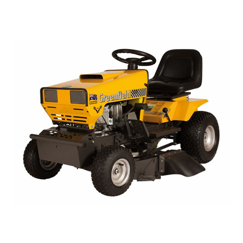
Greenfield GT04350 User manual

1
Owners Manual
Instrucons & Original Parts Lisngs
Model GT04350
I.P.D Slasher
Greeneld Mowers Pty Ltd
123 Boundary Rd, Rocklea. QLD 4106
Ph: (07) 3875 9400
F: (07) 3875 9425
E: info@greeneld.com.au
www.greeneld.com.au

2
Contents
Safety Instrucons 3
Mowing On Slopes 4
Operang Instrucons 5
Maintenance 6
V Belts 7
Blades 7
Engine, Frame & Wheels 10
Warranty 11
Cuer Deck 8
Handles, Controls & Covers 9

3
Thank you for purchasing an Australian made Greeneld product. Your Greeneld I.P.D (Industrial Power Drive) Slasher
is built for tough work and is ideal for large area lawn mowing and heavy scrub clearing. Please ensure to follow the
manufacturers safety, operang, and maintenance instrucons for many years of trouble free operaon and service.
Before operang the mower, read the owners manual carefully. Do not allow children or any person unfamiliar with
the safe operang procedure to operate this mower. Your Greeneld has been designed to meet stringent safety stan-
dards - but we remind you that a mower is a cung device - used incorrectly, it may cause personal injury or death.
Remove the key from the machine when not in use.
Safety Instrucons
1. WARNING - Disconnect the spark plug lead to avoid accidental starng before aempng any inspecon or main-
tenance.
2. Do not mow whilst people, especially children or pets, are in the mowing area. Children should be kept safely
supervised. Never assume that children will remain outside of the cung area. Do not reverse before looking
behind.
3. Ensure that the area to be mowed is clear of scks, stones, boles, bones, wire, and other debris that could be
thrown by the blades.
4.
Do not operate the machine without rst inspecng the blades, blade bolts, and blade holder for wear or
damage. Damaged blades or bolts are hazardous.
Always replace blades and blade bolts in sets to preserve
balance. Replace worn or damaged parts with genuine Greeneld replacement parts only. Use of inferior, non-
genuine service parts could result in damage or personal injury.
5. Never mow while barefoot or wearing sandals or thongs. Wear long trousers and heavy shoes. It is also important
to wear suitable hearing and eye protecon.
6. A mower operator should be in good physical and mental health and not under the inuence of any drug, alcohol
or any other substance that could impair vision, coordinaon or judgment.
7. Always refuel outdoors away from any ame sources. Do not smoke whilst refueling the engine, or fuel near a
source of ignion, such as electrical switches or gas hot water heater. Never remove the cap from the fuel tank
or add petrol whilst the engine is running or if the engine is hot, always allow to cool. Remove fuel cap slowly to
relieve any tank pressure. Do not overll the fuel tank. If petrol is spilled, do not aempt to start the engine, move
the machine away from the spill area and wipe the machine dry with a clean rag. Do not aempt to start the
machine unl all petrol and vapours have dissipated.
8. Check for fuel leaks when refueling. If a fuel leak is detected, do not start the engine unl the fuel leak is xed and
the spill is wiped away.
9. Use only an approved container for storing fuel. Never store fuel or the fueled machine in an unvenlated area or
near a source of ignion such as electrical switches or a gas hot water heater.
10. Do not run the engine in a conned space where carbon monoxide and poisonous exhaust fumes can collect.
Carbon monoxide is a colourless, odourless, deadly poisonous gas.
11. Always disengage the cung blades before starng or stopping the engine. NEVER walk in front of the Slasher
when the engine is running, even if the drive clutch is out.
12. Never mow up or down hill on slopes which exceed 10 degrees, or mow across the face of a slope which exceeds
5 degrees.
13. Stay alert for holes in the terrain and other hidden hazards.
14. Before crossing paths, driveways, or any other area foreign to mowers, reduce engine speed, disengage the cung
blades, and li the cung aachment to maximum height.
I.P.D Slasher Mower

4
1. Exercise extreme cauon when operang a ride-on mower on a slope. Slopes are a major cause of p-over and loss
of control accidents involving ride-on mowers. Severe injury or death can occur.
2. The manufacturer recommends that the single front castor wheel be replaced with the oponal dual wheel
assembly (GT00999) before aempng to mow any slope.
3. Owing to inadequate reacon to hazard mes, the large (fast) drive dogs should be replaced with the standard
small drive dogs when working on slopes.
4. Plan a mowing procedure that does not require sudden direconal changes or the drive to be engaged or
disengaged while on a slope.
5. Never operate on a mower on any slope if it is wet.
6.
A walk-behind mower should only be operated across a slope, never up or down. Disengage the drive clutch or
misplaced foong while working up or down an incline could result in the mower rolling back onto the operator or
running out of control down the slope.
7.
Before operang on a slope, remove all loose maer, branches, rocks, etc. and stay clear of holes, erosion, and tree
roots, etc. Such hazards can cause unexpected and instantaneous stability changes.
8. Do not use the grass catching aachment on slopes.
9. Do not mow close to steep drop os.
10. If a totally safe mowing procedure cannot be planned prior to entering a sloped area, an alternave method of
cung this area which does not risk the safety of the operator should be used.
If the operator of this Slasher is not absolutely certain a slope does not exceed the previous recommendaons, the
area should not be entered unl such me a properly qualied person has assessed and reported on the safety of the
area.
Mowing on Slopes
15. Watch out for trac when crossing or operang the mower near roadways. Always mow with the safety grass
deector properly ed.
16. Disengage the drive to the cung blades and stop engine:
(a) Before refueling.
(b) Before removing the grass catcher or any aachment.
(c) Before making a height adjustment, unless adjustment is being made from the operators posion.
(d) Before clearing blockages. (e) Before inspecng, cleaning, or working on the mower.
(f) Aer striking a foreign object (inspect the mower for damage and make necessary repairs before
restarng and operang the machine).
(g) If the machine starts to vibrate abnormally (check immediately).
17. Disengage the drive to the cung blades when not in use or if transporng.
18. Do not over-speed the engine or alter the governor sengs. Excessive speed is dangerous and shortens engine
life.
19. Do not allow grass, garden debris or grease to build up on the mower, parcularly around the engine. This
could be a re hazard.
20. Replace any unreadable warning or safety decals. 21. Do not lend or sell the mower without the owners
manual.
22. Mow only in good daylight.
23. Walk, never run whilst mowing.

5
Operang Instrucons
Top with clean, regular unleaded petrol only. Do Not Overll. Don’t ll above the high level mark on the tank. Make
sure that the petrol is free from impuries, parcularly water. Before removing the ller cap from the fuel tank to
refuel the machine, wipe or brush the area clean to prevent any dirt or debris from accidentally falling into the tank
when the cap is removed. Do not use stale petrol in your mower - add clean, fresh fuel only.
Before Starng - Please Do Not Proceed Before Reading Safety Instrucons.
Fuel
Check oil level by posioning the mower on level ground. Wipe or brush the area clean around the oil ller/ dipsck
cap, remove the dipsck and wipe clean, replace the dipsck - screwing carefully into posion. Remove again and sight
the oil level. Fill to the full mark. Do not overll. The dipsck must be rmly in place when the engine is running.
Engine Oil
Inate to the correct pressure, 20psi (140 KPa). Do not over inate.
Tyres
1. Disengage the cuer clutch (OUT).
2. Disengage the drive clutch (DISENGAGE).
3. Turn the fuel tap on (if ed).
4. Set the throle control to CHOKE.
5. To start a manual/ recoil start engine, grasp the rope handle and pull slowly unl resistance is felt, then pull the
cord rapidly to start the engine. If the engine does not start aer three (3) aempts, repeat the procedure with the
throle control in the FAST posion (no choke).
6. For an electric start model, turn the key to the START posion for ve (5) seconds. If the engine does not start, shi
the throle lever to FAST (no choke) posion and start again. Ensure that the key returns to the RUN posion when
the engine starts or aer each aempt to start. Allow the engine to warm for a minute before heavy work.
To Start The Engine
1. Disengage the drive (DISENGAGE).
2. Reduce the engine speed (shi throle control to SLOW).
3. Disengage the blade clutch (cuers OUT).
4. Allow engine to cool down by idling for approximately 1 minute before stopping.
5. For a manual/ recoil start mower, slide the throle control to STOP.
6. For an electric start model, turn the key to STOP.
7. Turn the fuel tap o.
EMERGENCY STOP - For electric start models, turn the key to STOP. For manual start models, shi the throle lever to
S T O P.
To Stop The Engine
The Greeneld I.P.D Slasher can be operated with or without the drive engaged. The drive engagement lever is located
on the console panel between the upper handle bars. Shi the lever up and into the catch to disengage the drive. Shi
the lever out of the catch and down to engage the drive. The drive should be disengaged before making sharp turns or
aempng to slow the forward speed of the mower. When mowing large, regularly mown areas the larger drive dogs
can be ed to increase the ground speed of the mower.
Drive
To Operate
The height adjustment lever is located on the le side of the engine. Shi the lever out and forward to select a lower
cung height or out and rearward to select a higher cut.
Cung Height
The cuer engage lever is located on the le side of the engine. Shi the lever out of the rear catch and into the front
catch to engage the cung blades. Reverse this acon to disengage the cung blades.
Cung Blades

6
The throle control lever is located on the le side of the control console. This lever incorporates the CHOKE control
for cold starng as well as the adjustment for engine revs SLOW to FAST. It also has the STOP funcon for manual/ recoil
start engines only. The stop funcon for an electric start model is incorporated in the key start switch.
Throle Control
To maintain the correct uid level in the baery, top with dislled water only to the high level mark shown on the
baery.
Note: If the I.P.D is not used for at least ve (5) hours a month, the baery will discharge and could sustain permanent
damage. Do not allow the baery to discharge. Regularly trickle charge with a current not exceeding 3 amps per hour
for three (3) to four (4) hours to prolong baery life. Keep the outside of the baery, especially the terminals, clean and
dry and check the baery is held securely.
Dry Baery: When inially charging a new DRY baery, each cell must be lled to the high level shown on the baery
with an electrolyte (dilute sulphuric acid) with a specic gravity of 1.26 at 20°C to 30°C. The baery must then be
allowed to stand for thirty (30) minutes before charging at a rate not exceeding 3 amps for four (4) hours.
Warning:
Persons not trained in the proper procedure to transfer uids containing acid or do not have the
necessary safety equipment on hand in case of a spill or exposure, should not aempt this procedure. Contact the
baery manufacturers local agent or an authorized Greeneld dealer.
Baery
Change the engine oil aer the rst ve (5) hours. Change more oen in heavy work or dusty condions. Drain the
engine oil whilst the engine is warm, then replace. Fill to the full mark indicated on the dipsck. Do not overll. Refer
to the specic manufacturers book to conrm oil and oil lter recommendaons and the precise method of checking
the oil level.
The components of the gearbox have been lubricated prior to the gearbox being sealed at the factory. The shas run
in large sealed ball bearings. No further lubricaon of the gearbox is required.
Lubricate all other pivong joints, lever points, and slides with engine oil.
Lubricaon
Electric start models have a key turn starter switch mounted in the control console. Turn the key OFF to stop the engine.
Electric Start
Maintenance
Service the air lter as per the specic engine manufacturers book. Clean or replace more oen in dusty condions.
Never operate the engine without the air lter correctly and securely ed, rapid and expensive wear will occur.
Air Filter
There are two (2) sizes supplied. The smaller set is for slow speed, heavy grassed areas, conned or uneven areas. The
larger set is for at, larger, regularly mown areas. To change the drive dogs, disengage the drive, stop the engine and
disconnect the spark plug lead to prevent accidental starng. Remove the nyloc nut and washer from the end of both
drive shas and slide o the drive dogs. Fit the new drive dogs onto the drive shas, making sure that the recess in the
end of the dogs engages over the pins in the drive sha. Ret the washers, nyloc nuts, and reconnect the spark plug
lead.
Drive Dogs
Check the pressure - inate to the correct pressure, 20psi (140 KPa). Do not over inate.
Tyres
Debris may clog the engines cooling system. Remove the blower housing and clean out grass debris to prevent
overheang and engine damage.
Cooling System

7
Check condion of blades, blade bolts and blade holder. Replace if damaged or
worn. Worn or damaged blades and bolts are a major hazard. Always replace worn
or damaged blades and bolts in sets to preserve balance.
Use only Genuine Greeneld branded replacement blades and bolts. Use of infe-
rior non-genuine replacement parts on your Greeneld could result in costly dam-
age or even personal injury.
Part numbers for blades and bolts are:
Blade set GT02140
Bolt set GT02110
Blade & Bolt set GT02141
To t new blades refer to illustraon A.
Tighten the blade bolt nut rmly. Correct torque is 44 Nm (32 .lbs). Blades must
be free to move but not loose. Lightly oil the blade pivot point before ng.
Blades
Clean o all grass and other debris before storing. Scks, stones, or an accumulaon of grass and other debris will
damage belts and fracture pulleys if they go through between the pulley and belt. When operang in these condions,
the cuer deck may require more frequent cleaning.
Never wash your I.P.D with a high pressure gun. Water and dirt could bypass the seals in the bearings causing
premature bearing failures and rusted pivot points.
Allow your I.P.D to cool aer use. The quenching contracon eect from hosing the machine when it’s at operang
temperature could also draw water and dirt into the bearings.
The best way to clean your I.P.D is to use a low pressure air hose or garden blower to blow the loose grass, etc. from
around the pulleys, belts, and the top of the cuer deck. Wash the exterior the same as you would your car. For
maximum machine life, do not spray water on the engine, pulleys or bearings. Re-oil all pivots aer washing.
Cleaning
Illustraon A
1. Disconnect the spark plug lead to prevent accidental starng.
2. Disengage the blade clutch and drive clutch.
3. Remove the front cover.
4. Remove the belt guide from the engine pulley.
5. Support the weight of the cuer deck then disconnect the liing chain.
6. Remove the belt from the pulleys and replace with Genuine Greeneld GT00382 V Belt.
7. Ret the liing chain, belt guide, and cover.
8. Reconnect spark plug lead.
To Change the Cuer Belt
Inspect both V belts and replace if damaged or worn. Both the drive belt and cuer belt on the Greeneld I.P.D Slasher
have automac tension adjusters. Lubricate the sliding and pivong mechanisms of these adjusters regularly.
Part numbers for V belts are:
Cuer V Belt GT00382
Drive V Belt GT00383
Important: For long service life, use only Genuine Greeneld branded V Belts. Refuse substutes.
V Belts

8
Index Part Number Descripon
1GT04005A Link - RH
2GT00730 Pivot Bush
3GT00350 Spring - Tension
4 GT00775 Frame
5 GT01867 Spring - Compression
6 GT04102 Cuer Brake Unit
7 GT04005 Link - LH
8 GT00382 V Belt - Cuers
9 GT00743 Bracket
10 GT00771 Lever - Cuers
11 GT01565 Knob
12 GT04060 Disengage Link
13 GT04099 Belt Guide
14 GT04093 Post
Index Part Number Descripon
15 GT04030 Stone Guard
16 GT00763 Cuer Deck
17 GT02110 Bolt Set
18 GT02140 Blade Set
19 GT02141 Blade and Bolt Set
20 GT09530 Disc Assembly
21 GT01966 Wiper
22 GT00635 Spacer
23 GT00589 Shield
24 GT07985 Spindle Housing Unit
25 GT05089 Spacer - Pulley
26 GT00402 Pulley
27 GT00328 Nut
1. Disconnect the spark plug lead to avoid accidental starng.
2. To remove the drive belt, the cuer belt must rst be removed from the engine pulley. Follow steps 1 to 4 of “O
CHANGE CUTTER BELT” then drop the cuer belt from the engine pulley only.
3. Release the tension spring from the drive belt idler pulley and slide the pulley back.
4. Remove the drive belt from the pulleys and replace with a Genuine Greeneld GT00383 V Belt.
5. Replace the tension spring to the idler pulley.
6. Replace the cuer belt onto the engine pulley, replace the belt guide and cover.
7. Reconnect spark plug lead.
To Change the Drive Belt
Cuer Deck

9
Index Part Number Descripon
1GT04335 Handle Bar Assembly
2GT00757 Handle Grip
3GT04325 Rod - Drive
4 GT01012 Washer
5 GT00579 Wave Washer
6 GT00730 Pivot Bush
7 GT02466 Nyloc Nut
8 GT04330 Lever - Drive
9 GT01565 Knob
Index Part Number Descripon
10 GT04324 Latch
11 GT10037 Bush
12 GT01567 Belville Washers
13 GT02413 Nyloc Nut
14 GT20169 Throle Lever
15 GT02026 Knob
16 GT04043 Drive Sha Cover
17 GT04356 Decal Set
18 GT00697 Front Cover
Handles, Controls & Covers

10
Engine, Frame & Wheels
Index Part Number Descripon
1GT01069 H.T Belt
2GT02021 Spring Washer
3GT01750 Flat Washer
4 GT12022 Extension
5 GT00731 V Pulley
6 GT01500 Key
7 GT00520 Grub Screw
8 GT01501 Spacer
9 GT01182 Spacer
10 Engine as Fied
11 Throle Cable
12 GT02336 V Belt Drive
13 GT00693 Pivot Rod Assembly
14 GT04345 Axle Assembly
15 GT00628 Collar
16 GT02046 Crinkle Washer
17 GT00608 Spacer
18 GT04304 Belt Tensioner Arm
19 GT23043 Bearing Adaptor
20 GT00396 Bearing
21 GT01012 Washer
22 GT05056 Spring Tag
23 GT01118 Bolt
24 GT00749 Spring
25 GT01179 Bush - Axle
26 GT04282 Link
27 GT07071 Spring - Compression
Index Part Number Descripon
28 GT04285 Height Adjuster Lever
29 GT04080 Gear Box & Sha Complete
30 GT00760P Flagee Plate
31 GT00760 Bearing
32 GT04305 Cuer Clutch Lever
33 GT04311 Link
34 GT04076 ‘A’ Frame
35 GT01864 Wheel Complete
36 GT01179 Bush
37 GT01899 Sleeve
38 GT04075 Fork Assembly
39 GT01155 Bolt
40 GT04355 Frame
41 GT04070A Clamping Bar
42 GT02233 Wheel Hub
43 GT00398 Bearing
44 GT00454 Tube
45 GT00453 Tyre
46 GT00912 Compete Wheel
47 GT04100 Axle
48 GT00739A Sleeve
49 GT04069 Wheel Complete
50 GT01930 Hub Cap
51 GT04280 Belt Guide
52 GT00728 Drive Dog Small
53 GT00732 Drive Dog Large

11
Warranty Registraon Details
This record should be completed and held by the purchaser and presented should service under warranty be required.
To register your warranty, please visit www.greeneld.com.au/product-registraon/ or alternavely, complete and
return the enclosed warranty card.
Please Record Your Reference
Salutaon: Mr / Mrs / Ms / Dr First Name: Inial: Surname:
Address: Suburb:
State: Postcode: Phone: Dealer:
Email: Purchase Date: / /
Model: Serial #:
Notes
Table of contents
Other Greenfield Lawn Mower manuals