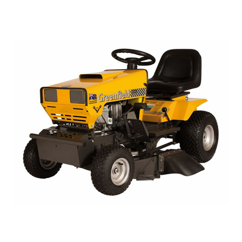
Greenfield GT22875 User manual

1
Owners Manual
Instructions & OE Parts Listings
Model GT22670
17.5/32 Standard
Model GT22690
17.5/32 Steel Deck
Model GT22875
25/32 Standard
Model GT22875SD
25/32 Steel Deck
Greenfield Mowers Pty Ltd
123 Boundary Rd, Rocklea. QLD 4106
Ph: (07) 3875 9400
F: (07) 3875 9425
E: info@greenfield.com.au
www.greenfield.com.au
Model GT22895
17.5/34 Deluxe
Model GT22900
25/34 V-Twin Deluxe
Model GT22885
25/42 V-Twin Deluxe

2
Contents
Safety instructions 3
Operating Instructions 6
Mowing on Slopes 8
Differential Instructions 9
General Maintenance 10
Brake System 12
Steering Adjustment 17
Idler Pulleys - Drive Belt
Linkages - Cuer Clutch and Drive Clutch
Linkages - Brakes, Cuer Height and Notch Bar
Chain Adjustment
Engine and Electrics
Drive Clutch and rear Axle
Electrical Circuits
Spare Parts
Warranty 30
Steering and Front Axle
Cuer Deck - 32” and 34”
Cuer deck - 42”
Body Work and Seat
Cutting System 13
Drive System 16
18
19
20

3
Thank you for purchasing an Australian made Greeneld FastCut ride-on mower. Please ensure to follow the
manufacturer’s safety, operang, and maintenance instrucons for many years of trouble free operaon and service.
Before operang the mower, read the owner’s manual carefully. Your Greeneld has been designed to meet stringent
safety standards - but we remind you that a mower is a cung device - used incorrectly, it may cause personal injury
or death. Remove the key from the machine when not in use. Do not allow children or any person unfamiliar with the
safe operang procedure to operate this mower.
Safety Instructions
1. Tesng the seat safety switch.
Acon: Park machine safely, sit on seat, apply park brake, set cuer engagement switch to o, start engine, switch
cuer blades on, raise body o seat but do not get o mower.
Result: Engine will begin to stop. Allow engine to fully stop. If the engine does not stop, there is a fault with the
seat safety switch. Do not aempt to use mower unl the seat safety switch has been inspected and repaired by
an authorized Greeneld dealer.
2. Do not carry passengers.
3. Know the controls. Read the operang instrucons carefully. Learn how to stop the mower and engine quickly in
an emergency.
4.
Do not mow whilst bystanders, especially children or pets, are in the mowing area. Children should be kept safely
supervised. Never assume that children will remain outside of the cung area. Do not reverse before looking
behind.
5. Ensure that the area to be mowed is clear of scks, stones, boles, bones, wire, and other debris that could be
thrown by the blades.
6.
Do not operate the machine without rst inspecng the blades, blade bolts, and blade holder for wear or
damage. Damaged blades or bolts are hazardous.
Always replace blades and blade bolts in sets to preserve
balance.
Replace worn or damaged parts with genuine Greeneld replacement parts only. Use of inferior, non-genuine
service parts could result in damage or personal injury. Refer Maintenance Instrucons pg. 10 for part numbers and
ng instrucons.
7.
Before using, check that the grass catcher (if installed), safety switches, and guards provided by the
manufacturer are operang properly and are ed securely. Regularly check all components on the mower to
ensure the machine is in a safe operang condion.
8. Never mow while barefoot or wearing sandals or thongs. Wear long trousers and heavy shoes. It is also important
to wear suitable hearing and eye protecon.
9. A mower operator should be in good physical and mental health and not under the inuence of any drug, alcohol,
or any other substance that could impair vision, coordinaon, or judgment.
10. Replace worn or faulty exhaust muers.
11. Do not allow grass, garden debris, or grease to build up on the mower, parcularly around the engine. This could
be a re hazard.
12. Always refuel outdoors away from any ame sources. Do not smoke whilst refueling the engine, or fuel near a
source of ignion, such as electrical switches or a gas hot water heater. Never remove the cap from the fuel tank
or add petrol whilst the engine is running or if the engine is hot, always allow to cool. Remove fuel cap slowly to
relieve any tank pressure. Do not overll the fuel tank. If petrol is spilled, do not aempt to start the engine, move
the machine away from the spill area and wipe the machine dry with a clean rag. Do not aempt to start the
machine unl all petrol and vapours have dissipated.
Series

4
13. Use only an approved container for storing fuel. Never store fuel or the fueled machine in an unvenlated area
or near a source of ignion such as electrical switches or a gas hot water heater.
14. Do not run the engine in a conned space where carbon monoxide and poisonous exhaust fumes can collect.
Carbon monoxide is a colourless, odourless, deadly poisonous gas.
15. Always disengage the cung blades before starng or stopping the engine.
16. Always mount or dismount the mower from the opposite side to the discharge chute. Always stop the engine
before dismounng. Keep hands and feet clear of the cuer deck.
17. Reduce speed, parcularly when making sharp turns, to prevent overturning or loss of control. Do not stop or
start suddenly when mowing up or down hill. The dierenal acon must be locked out when operang on any
slope to improve tracon, braking, and safety.
18. Never mow up or down hill on slopes which exceed 10°, or mow across the face of a slope which exceeds
5°. Before aempng to mow on any slope, refer to Mowing on Slopes pg.8.
19. Stay alert for holes in the terrain and other hidden hazards.
20. Before crossing paths, driveways, or any other area foreign to mowers, reduce engine speed, disengage the
cung blades, and li the cung aachment to maximum height. Do not drive over obstacles or guers, this
machine has a maximum clearance of 3.5” or 9cm.
21. Watch out for trac when crossing or operang the mower near roadways. Always mow with the safety grass
deector properly ed.
22. When mowing, never direct discharge of material toward bystanders, nor allow anyone near the machine while
in operaon.
23. Before leaving the operator’s posion:
(a) Disengage the cung blades.
(b) Apply the parking brake.
(c) Stop the engine and remove the starter key.
24. Disengage the drive to the cung blades and stop engine:
(a) Before refueling.
(b) Before removing the grass catcher or any aachment.
(c) Before making a height adjustment, unless adjustment is being made from the operator’s posion.
(d) Before clearing blockages.
(e) Before inspecng, cleaning, or working on the mower.
(f) Aer striking a foreign object (inspect the mower for damage and make necessary repairs before restarng
and operang the machine).
(g) If the machine starts to vibrate abnormally (check immediately).
25. Disengage the drive to the cung blades when not in use or if transporng.
26. Do not over-speed the engine or alter the governor sengs. Excessive speed is dangerous and shortens engine life.
27. Use care when pulling loads or using aachments:
(a) Use only the approved draw-bar hitch point.
(b) Limit loads to those you can safely control.
(c) Do not turn sharply. Use care when backing up.
28. Replace any unreadable warning or safety decals.
29. Do not lend or sell the mower without the owner’s manual.
30. Warning -
Remove the spark plug lead to avoid accidental starng before aempng any maintenance or
inspecon of the mower.

5
Safety Instructions
Read The Operator’s Manual(s) -
Read, understand, and follow all instrucons noted in the
manual(s) before aempng to operate.
Warning - Never carry passengers. Never carry children, even with the blades o.
Operator Awareness - Always look down and behind before and while backing to avoid a back-over
accident.
Warning (Rotating Blades) - Do not place hands or feet near rotang parts or under the cung
deck. Contact with the blade(s) can cause serious personal injury.
Warning - Remove spark plug lead and ignion key. Read instrucons before servicing or performing
maintenance.
Bystanders - Keep bystanders, helpers, children, and pets at least 25 metres from the machine
while it is in operaon with a compliant safety deector.
Warning (Slope Operation) - Do not operate this machine up or down a slope greater than 10° or
5° across.
Warning (Hot Surface) -
Engine parts, especially the muer, become extremely hot during
operaon. Allow engine and muer to cool before touching.
Warning - Keep bystanders at a safe distance from the machine.
Warning - Turn o engine and remove ignion key before refueling the machine.
Caution - Avoid injury! Engine exhaust fumes contain carbon monoxide and can cause serious ill-
ness or death.
Caution - Do not run an engine in an enclosed area such as a garage, even with the doors and
windows open.
The following images depict and describe safety symbols that may appear on this product. Please read, understand,
and follow all of the safety instrucons before aempng to assemble or operate this product.

6
Operating Instructions
Top with clean, regular unleaded petrol only. Do Not Overll. Do not ll above the high level mark on the tank. Make
sure that the petrol is free from impuries, parcularly water. The petrol tank is located inside the engine
compartment. Raise the bonnet for access. Before removing the ller cap from the fuel tank to refuel the machine,
wipe or brush the area clean to prevent any dirt or debris from accidentally falling into the tank when the cap is
removed. Do not use stale petrol in your mower - add clean, fresh fuel only.
Before Starting - Please Do Not Proceed Before Reading Safety Instructions.
Fuel
Check oil level by posioning the mower on level ground. Wipe or brush the area clean around the oil ller/ dipsck
cap, remove the dipsck and wipe clean, replace the dipsck - screwing carefully into posion. Remove again and sight
the oil level. Fill to the full mark. Do not overll. The dipsck must be rmly in place when the engine is running. Refer
to Crankcase Lubricaon pg.10 for oil recommendaons.
Engine oil
Inate to the correct pressure, 20 to 22 psi (140 to 154 KPa) in the front tyres and 12 to 15 psi (84 to 105 KPa) in the
rear tyres. Do not over inate. Over inaon will change the shape of the tyre, adversely aecng the cuer trim and
lt, and may also cause permanent tyre damage, resulng in tyre rupture and possible accident.
Tyres
The cung height adjustment lever is located in the rear cover to the front of the operator. To alter the cung height,
move the lever to the right then shi upward or downward to select the seng, then release to lock in posion. An
indicator panel displays the seng. Use the height seng in the green band for maximum belt life.
Cutting Height
The blade clutch switch is located on the right hand side of the dash panel. To ENGAGE the cuer blades, pull the
switch up. To DISENGAGE the cuer blades, push the switch down.
DANGER:
• When cuer clutch is engaged, high-speed blades are rotang.
• Never use the mower without the safety deector or grass catcher ed.
• Never aempt to dismount from the driver’s seat while engine is running.
Blade Clutch
The operator’s seat is adjustable front to rear. To adjust, push the lever on the le hand side of the seat to the le and
slide the seat forward or backward unl a safe and comfortable seang posion is obtained, then release the lever to
the locked posion. Oil the slides occasionally. The seat is ed with a safety switch. See Tesng Procedure pg.3.
Seat
Apply the park brake, disengage the blade clutch (cuers out). Turn on fuel tap (if ed). For cold starng, the choke
will need to be acvated. On single cylinder models, move the throle control lever up and into the CHOKE posion.
On twin cylinder models ed with a separate choke control, move the throle control to the FAST posion and pull
out and hold the choke control in the choke posion. Turn the starter key to the start posion for a maximum of ten
(10) seconds, to avoid overheang the starter motor. If the engine does not start, it may be ooded. Set the throle
control half way and try again.
Make sure to return the key to the RUN posion aer the engine starts or each me you aempt to start it. Once the
engine is running, move the throle control to the FAST posion on single cylinder models to turn o the CHOKE.
On twin cylinder models with separate choke control, push the CHOKE in fully for correct engine operaon.
To Start The Engine
Important - This Greeneld mower is ed with a safety ‘Cut-Out’ switch, acvated by the seat. The operator must
be seated to start the engine and remain seated while operang the mower. If the operator does not remain seated,
the engine will stop. This safety switch must be kept funconing for your protecon. Adjustment is easily done when
necessary.

Drive Control
Foot Pedal
Remove Foot for Neutral
Reverse
Forward
7
In an emergency situaon, turn the key to the STOP posion.
For a normal stop, reduce the engine speed to idle on the throle control, disengage the cuer blades.
Apply the park brake and allow the engine temperature to even out by idling for approximately twenty (20) seconds.
Turn the key to the STOP posion.
Note: Some manufacturers require their engines be stopped in a dierent manner i.e. Briggs & Straon recommends
that their single cylinder engines be shut down at full revs. Please refer to the engine manufacturers book supplied with
this machine for their recommended engine stopping procedure.
Only aer the mower, the engine, and all mechanical funcons of the mower have completely stopped should the
driver dismount from the driver’s seat.
Remove the key and store out of reach of children. This will also ensure that the hour meter will not connue to run
and that power to the electric fuel solenoid valve on the carbureor is shut o.
To Stop The Engine
A simple pivoted mul-purpose foot pedal operated by the driver’s right foot
controls forward, neutral, and reverse. Apply toe pressure to move forward, heel
pressure to move in reverse. Increased toe or heel pressure provides speed
variaon in forward or reverse respecvely. Allow pedal to centralize for neutral. The
manufacturer also recommends this mul-purpose pedal be used as the principle
method of braking when operang this mower. On level ground or moving forward
downhill, the mower can be slowed or stopped by applying toe or heel pressure
opposite to the direconal movement of the mower. When moving forward up hill,
regulang the forward pressure will stop or slow the mower. Sudden or violent
direconal changes and/ or wheel spinning must be avoided. For a detailed explanaon
of the braking systems on this Greeneld FastCut mower, see the secon on Braking
Systems pg.12.
To Operate
Recommended method to proceed down slopes:
Before driving down a slope, shi the throle control to select slow engine revs.
Using toe pressure, keep the mul-purpose foot pedal engaged in the FORWARD drive posion while driving down
the slope. This will limit the forward speed of the mower to the preselected engine speed. To further adjust the
ground speed to suit the condions, use the throle control to raise or lower the engine revs while sll retaining
the necessary toe pressure on the foot pedal to keep forward drive engaged. This pracce eliminates unnecessary
wear and tear on clutches, transmissions, and tyres caused when reverse is used to slow the forward progress of the
mower on slopes. This pracce also ensures that the operator retains beer control of the machine as engaging
reverse in certain circumstances, such as wet grass, could cause the wheels to skid, which may result in loss of
control. Reverse or heel pressure will be needed to stop the mower.
IMPORTANT: Never drive a ride-on mower up or down a slope exceeding 10° or across a slope exceeding 5°.
Safe Operating Hint

8
Mowing on Slopes
Exercise extreme cauon when operang a ride-on mower on a slope. Slopes are a major cause of p-over and loss of
control accidents involving ride-on mowers. Severe injury or death can occur.
On any slope, the dierenal acon must be locked out for best tracon and braking i.e. both rear wheels driving.
Speed should be reduced on slopes, parcularly when changing direcon.
Do not stop or start on slopes or make sudden speed or direconal changes unless enrely necessary.
Never operate a ride-on mower on any slope if it is wet. Any grass in good condion on slopes can cause your
ride-on mower to slide and cause the brakes to have lile or no eect.
A ride-on mower should only be operated up and down slopes, not across.
Before operang on a slope, remove all loose maer, branches, rocks, etc. and stay clear of holes, erosion, tree roots,
etc. Such hazards can cause unexpected and instantaneous stability changes.
If a totally safe mowing procedure cannot be planned before entering a sloped area, then an alternave method of
cung the area which does not risk the safety of the operator should be used.
Never tow or use any oponal aachment on ANY slope.
Do not mow close to steep drop os.
Never mow up or down hill on slopes
which exceed 10°.
Never mow across the face of a slope
which exceeds 5°.
If the operator of a ride-on mower is not absolutely certain that a slope does not exceed the previous
recommendaons, the area should not be entered unl such me as a properly qualied person has assessed and
reported on the safety of the area.
Maximum Slopes

Key
GT00516
Engagement Plate
GT02868
Wheel Hub
GT02929
M10 Wheel Nut x 3
GT02861
Keyed Engagement Block
GT02956
Engagement Handle
GT02957
Spring
GT02958
Retainer
GT10488
Screw
GT02425
Differential
Locked
Differential
Operating
9
Some Greeneld FastCut models feature a unique and patented dierenal. This dierenal oers the operator the
opon of the full dierenal acon of the rear wheels for improved steering and a ght turning circle, whilst
eliminang rear wheel scung on ne lawns. Most people will operate their Greeneld mower with the dierenal
operang at all mes. This is the preferred method of operaon and is accomplished by keeping the handle hooked
over the end of the rear axle. See illustraon below.
IMPORTANT: Do not aempt to engage or disengage the dierenal lock from the operator’s seat while the
engine is running.
In situaons such as wet areas, uneven terrain, slippery surfaces, and parcularly when working on any slope, you
must lock out the dierenal acon i.e. both rear wheels driving for improved tracon and braking. This dierenal
must also be locked out when using any aachment such as a dozer blade or when towing. Locking the dierenal is
accomplished by releasing the handle from the end of the rear axle. See B Below. Slight movement of the mower with
the front wheels, other than straight ahead, may be required to engage the locking mechanism.
To return the dierenal to the operang posion, see illustraon below, turn the steering wheel either to the le or
right. Rock the mower back and forth while simultaneously pulling out the engagement handle and locang it over the
end of the axle. Lubricate if necessary.
If the le side rear wheel is removed, make sure that the keyed engagement block slides freely into the square secon
of the engagement plate before nal ghtening of the wheel nuts.
Greeneld dierenals are fully lubricated and sealed for life at the factory. If in the unlikely event that your dierenal
needs service, it must be returned to Greeneld intact. Dierenals that have been tampered with or dismantled will
NOT be considered for warranty. Normal warranty is twenty four (24) months for private use and three (3) months for
commercial use. Extended warranty is available for up to ve (5) years for private use if the servicing condions are
maintained. See your Greeneld dealer for details. During the warranty period, service and spares for dierenals are
only available through the factory.
Greenfield Differential

10
Maintenance
Warning: Remove the spark plug lead to avoid accidental starng BEFORE aempng any maintenance or
inspecon of the mower.
Change the engine oil aer the rst ve (5) hours of operaon, then every six (6) months or twenty ve (25) working
hours, whichever comes rst. Change more oen in heavy work or dusty condions. Drain the engine oil whilst the
engine is warm then replace. Refer to the engine manufacturer’s book supplied with this machine for specic grade
required for this engine. Briggs & Straon recommends Warranty Cered SAE 30 oil, available from Briggs & Straon
service dealers.
Fill to the full mark indicated on the dipsck. Do not overll. Check oil level by posioning the mower on level ground.
Wipe or brush the area clean around the oil ll/ dipsck cap, remove the dipsck and wipe clean, replace the dipsck
- screwing carefully into posion. Remove again and sight the oil level. Fill to the full mark. Do not overll. The dipsck
must be rmly in place when the engine is running.
Crankcase Lubricaon
Service the air lter as per the engine manufacturer’s booklet. Clean or replace more oen in dusty condions. Never
operate the engine without the lter correctly and securely ed - rapid and expensive wear to the engine will occur.
Air Filter
Remove the blower housing and clean out the grass and debris to prevent engine overheang. Refer to the engine
manufacturers booklet.
Cooling System
A maintenance free baery is ed to your machine.
Note: If the mower is not used for at least ve (5) hours a month, the baery will discharge and could sustain
permanent damage. Do not allow the baery to discharge. Regularly trickle charge the baery with a current not
exceeding three (3) amps per hour for three (3) to four (4) hours to prolong the baery life. Keep the outside of the
baery, especially the terminals, clean and dry and check the baery is held securely.
The maintenance of the baery is the customer’s responsibility, only faulty baeries are covered by the baery
manufacturer’s warranty. Neglect is not covered.
Battery
The rear wheel nuts should be re-tensioned aer the rst ve (5) hours of operaon to 44Nm (33 lbs), then regularly
with your preventave maintenance checks. Before re-tensioning the L.H rear nuts on models ed with dierenals,
make sure that the key engagement block slides freely into the engagement plate.
Wheels
Inate to the correct pressure, 20 to 22 psi (140 to 154 KPa), in the front and 12 to 15 psi (84 to 105 KPa) in the rear.
Do not over inate.
Tyres
Regularly check the condion of the cuer blades and blade bolts, cuer disc, V belt and pulleys, and cuer brake.
Refer to specic secons of the manual for further details regarding blades, V belts, etc.
Cutter Deck

Lightly Oil Here
11
Never wash your Greeneld mower with a high pressure wash gun. Water and dirt could be blasted past the seals in
the bearings, causing premature bearing failures and rusted pivot points.
•
Never wash your Greeneld mower immediately aer use. The quenching contracon eect from hosing the
machine while at operang temperature could also draw water and dirt into the bearings and cause premature
bearing failures.
• The best way to clean your Greeneld is to use an air hose to blow loose grass, etc. from around pulleys, belts,
and the top of the cuer deck. Wash the exterior with a sponge and bucket, then rinse o with a hose and wipe it
down the same way as you would a car. For maximum machine life, do not spray water directly on the pulleys and
bearings.
• Allow your Greeneld to cool aer use, then clean o all grass and other debris before storing. Scks, stones, or
an accumulaon of grass and other debris will damage belts and fracture pulleys if they go between the pulley and
belt. When operang in these condions, the cuer deck may require more frequent cleaning.
Cleaning
Your Greeneld mower has three (3) greasing points. A grease nipple is ed to each king pin housing in the front axle
beam, the third grease nipple is ed to the steering idler which is located on the centre of the machine close behind
the front axle beam and accessible from under the chassis. Grease these locaons every y (50) hours with a quality
No. 2 lithium base grease or equivalent. It is recommended that your grease gun be ed with a exible hose for easier
access. All other exposed pivot joints, lever points, and slides are to be lubricated with engine oil.
Chassis Lubrication
V belts on Greeneld mowers are self adjusng, although the cuer belt may occasionally require an extra manual
adjustment within its working life. See pg.20. Inspect the V belt regularly and replace if damaged. Part numbers for V
belts are:
32” and 34” Drive V Belt - GT02369 42” Drive V Belt - GT12004
32” and 34” Cuer V Belt - GT02365 42” Cuer V Belt - GT02627
IMPORTANT: To prolong service life, use only genuine Greeneld branded V belts, refuse substutes, non genuine V
belts may render the clutch ineecve, even dangerous.
Belts
Check condion of blades, blade bolts, and blade holder. Replace if damaged or
worn. Damaged or worn blades and bolts are a serious hazard. Always replace
damaged or worn blades and bolts in sets to preserve balance. Use only genuine
Greeneld branded replacement parts. Use of inferior non genuine replacement
parts on your Greeneld mower could result in costly damage or personal injury.
Part numbers for blade and bolt sets are:
32” and 34” Cuer Blade and Bolt Set - GT02139
42” Cuer Blade - GT02632
Illustraon A shows ng procedure for cung blades. Tighten the blade bolt
nuts rmly. Use a 17mm ring spanner. The correct torque is 44Nm (32 lbs). The
blades must be free to move but not loose. Lightly oil the blade pivot point before
ng.
Warning: Always remove the spark plug lead to avoid accidental starng.
Cutter Blades
Illustration A

12
Greenfield FastCut Braking Systems
This Greeneld ride-on mower is equipped with a mul-purpose Drive/Brake Control Pedal, operated by the driver’s
right foot. It also has an Emergency Brake operated by the le foot and a hand operated Parking Brake. All three
systems are completely independent of one another.
The manufacturer recommends the pivoted Drive/Brake Control Pedal, operated by the driver’s right foot, should be
used as the principle method of braking when operang this mower. The Emergency Brake, operated by the driver’s
le foot, should only be used in an emergency i.e. if the drive/brake pedal ceases to funcon for any reason. The
Parking Brake should only be engaged aer the machine has come to a stop, although this brake can also be used in an
emergency if both other systems have failed.
The recommended Drive/Brake system incorporates two large and very durable low speed clutches that control
forward, reverse, and stopping as selected by the driver. This Drive/Brake system will provide excellent and trouble
free service for all driving and braking requirements for many years under normal condions.
The Emergency Brake, operated by the driver’s le foot, engages a disc brake on the mower’s rear axle. Disc brakes
require expendable brake pads to slow the rotaon of the brake disc. If used only as an emergency brake, as the
manufacturer intends, this brake will not require replacement brake pads for many years, if ever. If however, this brake
receives connual use, the brake pads will quickly wear, requiring regular adjustments and periodic brake pad
replacement.
Under no circumstances should the Emergency Brake be applied whilst the driver is simultaneously acvang the
Drive/Brake pedal. As with all Greeneld mowers, the warranty covers faulty workmanship and materials.
Consumable items, such as brake pads, are not included in the warranty.
As with any brakes, they become less eecve in wet condions and can lose grip on well grassed areas, parcularly if
the grass is in a lush condion or wet. Therefore, it is very important to read and understand all the Safety Instrucons
included throughout this book and parcularly the secon tled Mowing on Slopes that indicates, amongst other
important informaon, the maximum degrees of slope that mowers should be operated on.
IMPORTANT: Read and understand all safety and operang instrucons in this book. Know the controls. Be sure the
area that you are about to enter has no concealed hazards and does not exceed a 10° incline or decline or 5° across.
Periodically test the Emergency Foot Brake. If adjustment is required, follow the instrucons below. The adjusng
screw is located on the brake arm and bears against the sliding brake pad. As the brake pads wear, the brake disc is free
to centralize between the sliding pad and the xed pad. This adjusng screw compensates for wear on both pads and
can be adjusted as described below.
1. Remove the spark plug lead to prevent accidental starng.
2. The adjusng screw is posioned at the rear of the mower, up and inside of the chassis. Access is easier if the rear
of the mower is elevated slightly e.g. place rear wheels on 30cm blocks. Ensure mower cannot roll.
3. Loosen the locknut and screw in the adjusng screw unl the brake pads have minimum clearance on the brake
disc and are not binding.
4. Tighten the locknut while holding the adjusng screw staonary.
5. Check that the brake disc rotates freely between the pads, then replace the mower onto the ground.
6. Replace the spark plug lead.
Brake Pad Wear Adjustment
1. Follow steps 1 & 2 of Brake Pad Wear Adjustment.
2. Remove the pad retainer sha.
3. Remove both brake pads by sliding down from rear of mower.
4. As the new pads will be thicker, it will be necessary to release the locknut and screw out the brake pad adjusng
screw.
5. Fit the new brake pads.
6. Ret the pad retainer sha.
7. Readjust the adjusng screw following steps 1 to 5 of Brake Pad Wear Adjustment. See Illustraon B.
8. Oil all Pivots. Do Not Oil Brake Pads or Disc.
Brake Pad Replacement

Adjustment Screw
& Lock Nut
Pad Retainer Bolt
Pad Retainer
Brake Pads
A
A +6mm
**
*Both sides equal height
Tilt Trim
Trim Adjusting Nut
Tilt Adjusting Bolt
Tilt Adjusting Bolt
(One each side)
Trim Adjusting Nut
(One each side)
13
Cutting System
Before checking TILT, which is the forward slant on the Cuer Deck from front to rear, or TRIM, which holds the Cuer
Deck level side to side, rst check the tyres are inated to correct pressures. Also that the front axle beam is level in
the chassis and all four wheels are on the same level, at surface.
1. Remove the spark plug lead to prevent accidental starng.
2. Disengage blade clutch, SWITCH OFF.
3. Set the Trim by adjusng the trim adjusng nuts located on the top liing arms of the cuer deck.
4.
Set the Tilt by loosening the lt adjusng bolts, which connect the boom liing arms to the cuer deck side plates.
5. Set the deck to the correct lt (minimum 6mm lower at the front) then re-ghten both bolts. See illustraon C.
Cutter Deck Adjustment
Illustration B
Illustration C

14
Warning: Remove the spark plug lead to avoid accidental starng BEFORE aempng any maintenance or
inspecon of the mower.
The self-adjusng belt tensioner will automacally adjust to compensate for normal wear and stretch of the V belt.
However, as most belt stretch occurs during the early operang hours of the new belt, the rst adjustment should be
checked aer approximately ve (5) hours of operaon with further checks at the y (50) hour services. Belt tension
can easily be adjusted at the xed idler pulley.
The xed idler pulley has seven (7) bolt hole posions available, plus a sliding adjustable base. To adjust the belt using
the xed pulley bracket, disengage the cuers then loosen the two (2) Nyloc Nuts on the pulley bracket base and slide
the bracket rearward and re-ghten the nuts, or relocate the pulley to the next rearward hole.
Cutter Belt Adjustment
To Remove Cutter V Belt
1. Remove the spark plug lead to prevent accidental starng.
2. Lower the blade height to the LOW posion.
3. Check the blade clutch is disengaged, SWITCH OFF.
4. Remove the V Belt from the engine pulley.
5. Undo the centre nuts and remove the belt guards.
6. Remove the V Belt from the cuer spindle pulley and remove the V Belt from the machine.
To Replace Cutter V Belt
1. Remove the spark plug lead to prevent accidental starng.
2. Lower the blade height to the LOW posion.
3. Check the blade clutch is disengaged, SWITCH OFF.
4. Fit the V Belt to the cuer pulley by maneuvering the belt around the pulley .
5. Posion the belt guard over the bolt and engage on the bracket (ensure the correct guard is used - le and right
sides are dierent - compare to illustraon). With the wings of the belt guard over the belt and pulley, ret the
washer and Nyloc Nut. See illustraon.
IMPORTANT: Before progressing to the next step, check that both pulleys spin freely inside the belt and belt guards
when the cuer clutch is disengaged.
6. Fit the V Belt to the boom groove of the engine pulley. Refer to illustraon E showing cuer V belt run.
7. Replace the spark plug lead.
8. From the operator’s seat, run the engine and engage the cuers to check the V Belt operaon. Refer to Cuer Belt
Adjustment.
Note: A belt run-in period is required as follows - with the height adjusng lever in the green band (mid height
posion) engage cuer blades and run for a minimum of ten (10) minutes at medium engine speed. Ideally, a total
run-in me would be approximately one (1) hour, during which me you can cut grass on a mid height posion.

Sliding Bracket Pulley
Fixed Bracket Pulley
Cutter V Belt
GT02627
Electric Clutch 42”
GT02630
Cutter V-Pulley
Belt Guide
Cutter V Belt Run
Illustration D
42
Illustration D
Note location and lower alignment hole width for Belt Guide.
A
R
L
A
A
A
GT02466 Nyloc Nut
* GT22656 Belt Guide RH* GT22655 Belt Guide LH
GT02466 Nyloc Nut
E
32/34
Sliding Bracket Pulley
Fixed Bracket Pulley
Cutter V Belt
GT02627
Electric Clutch
32”/34” - GT02619
Cutter V-Pulley
Belt Guide
15
Cutter V Belt Run

Steady Bracket
Hook Tool
Leaf Spring
Flat Head
Screwdriver
Idler Pulley
on Notch Bar
Flat Idler Pulleys
V Allignment
Pulley
Clutch Pulleys
Flat Allignment
Pulley
Illustration F
Illustration H Illustration I
Rear Clutch Link
Illustration G
16
1. Remove the spark plug lead to prevent accidental starng.
2. Remove the rear cover as follows - Li up the seat and disconnect the wire to
the seat cut out switch by separang the spade connector on the blue wire near
the top of the baery. Undo the star knob at the top rear of the rear cover and
posion the height adjustment lever in a mid height posion. Now remove the
rear cover and seat assembly.
3. Set the blade height to the LOW posion.
4. Swing back the steady bracket supporng the rear clutch link. Refer illustraon F.
5. Remove the spring clip retaining the rear clutch link to the yoke. Li o the rear
clutch link and swing rearward. Refer illustraon G.
6. With a spring release hook tool. See illustraon H. Remove the tension spring
from the idler pulley notch bar.
7. Release the notch bar leaf spring by inserng a at screwdriver through the slot
in the bracket above the leaf spring. Lever the leaf spring clear of the notch bar
and hold in a released posion, allowing the idler pulley to slide freely rearward
to permit belt removal. Refer illustraon H.
8. To remove the drive V Belt from the engine pulley, the cuer V Belt must rst
be removed. Follow steps 1 to 4 of To Remove Cuer V Belt instrucons. Now
remove the Drive V Belt from the engine pulley.
9. Li the drive V Belt o both at idler pulleys and remove the belt through the
opening at the rear clutch link.
Drive System
To Remove Drive V Belt
1.
Feed enough belt down the back of the clutch pulleys to reach the engine pulley. Guide the belt over the cuer belt
guide bar and underneath the engine pulley and into the top groove of the engine pulley. If the cuer V Belt is in
posion on the engine pulley, remove the belt by following steps 1 to 4 of To Remove Cuer V Belt.
2. Place the belt around both the V and Flat alignment pulleys and over the two at idler pulleys. Place the belt into
both clutch pulleys then into the idler pulley on the notch bar. This pulley will need to be in the fully rearward
posion to t the belt, then slide it forward. Lubricate the slide with grease before ng the belt.
3. Check the belt is sll correctly in place over both the alignment pulleys and both the at idler pulleys. The back of
the belt runs on all at pulleys. See illustraon I.
4. Replace the notch bar tension spring using a hook tool.
5. Replace the rear clutch link and the spring clip.
6. Swing the steady bracket forward to support the rear clutch link.
7. Ret the Cuer V Belt by following steps 6 and 7 of To Replace Cuer V Belt instrucons.
8. Replace the rear cover and reconnect the wire to the safety cut out switch for the seat.
9. Replace the spark plug lead.
To Replace Drive V Belt

Illustration J
Illustration F
Adjustable
Stops
Steering Chain
Chain Sprocket
Support
Steering Link
Grease Nipple
Front Axle Beam
Steering Crank
Tie Rod
Tie Rod
Front Wheel
Steering Stops
Viewed from underside
and shown on full lock
Grease Nipple
Item C Item A
Tie Rod End
Item B
Fixed Stop
Illustration G
17
Steering Stop Adjustment
The steering stops (Item B) are readily seen and accessible from under the right hand side of the chassis with the cuer
deck in the LOW posion. Adjustments should not be necessary, unless the steering has been damaged.
1. Remove the spark plug lead to prevent accidental starng.
2. Check the front wheel alignment, correct if necessary by reseng the adjustable e rods. Also check that the
steering wheel spokes are horizontal when the front wheels are in the straight-ahead posion. Adjust the steering
link if necessary. These adjustments must be completed before any steering stop adjustments are made.
3. Loosen the nuts retaining the two steering stops on the chain sprocket support. Refer illustraon J (item B).
4. Turn the steering wheel full lock to the right unl the right hand king pin is hard against the xed stop (Item A).
5. Slide the right side stop on the chain wheel support unl it hits against the e rod end (Item C). Re-ghten the
locking nut (Item B).
6. Turn the steering wheel full lock to the le then repeat step 5 above.
7. To check your adjustments are correct, turn the steering wheel to either lock, nong stops (Item A and Item B)
make contact at the same moment. This will ensure the smallest turning circle without unnecessary strain on the
steering components.
8. Replace the spark plug lead.

18
Chain Adjustments
1. Remove the spark plug lead to prevent accidental starng.
2.
Remove the rear cover as follows - Li up the seat and disconnect the wire to the seat cut out switch by
separang the spade connector on the blue wire near the top of the baery. Undo the star knob at the top rear of
the rear cover and posion the height adjustment lever in a mid height posion. Now remove the rear cover and
seat assembly.
3. Loosen the two locking nuts on the chain adjuster mechanism, only enough to allow the mechanism to slide. Use
a 14mm ring spanner or socket.
4. Undo the front adjusng nut on the screw adjusng mechanism, using a 13mm open-end spanner.
5. Using the same spanner adjust the back adjusng nut to take up excess slack in the drive chain. The chain is
tensioned correctly when the slack has been reduced to approximately 3mm. Do not over tension.
6. Re-ghten the two locking nuts. Recheck the chain tension. If necessary the procedure may need to be repeated
and the adjusng nut backed o slightly to comply with the recommended chain tension.
7. Re-ghten the front adjusng nut.
8. Replace the rear cover, the star knob and reconnect the wire to the safety cut out switch for the seat.
9. Replace the spark plug lead.
Rear Drive Chain Adjustment

BU
Starter
Motor
Hour Meter
PTO Switch
Key Switch
Lights
Light Switches
Red Warning Light
Seat Switch
Battery
Magnetic Clutch
& Brake
Pressure
Switch
Fuse
Starter
Solenoid
Y
1
2
5
4
3
10
7
6
8
9
R
R
R
R
R
R
B
B
B
B
BU
W
OO
R
Index
1
2
3
4
5
6
7
8
9
10
Part No.
GT 6129
GT 14364
GT 14370
GT 20219
GT 22047
GT 20216
GT 20215
GT 20197
GT 20196
GT 22037
Description
Red Cable - Solenoid to Starter Motor
Red Cable - Battery to Solenoid
Black Cable - Battery to Engine Ground
Red Wire - Key Switch to Hour Meter
Wiring Harness - Key Switch
Red Wire - Warning Light
Black Wire - Oil Switch
Wire Harness - Light Switch
Wire Harness - Headlights
Seat Switch Harness
Colour Legend
B - Black
O - Orange
R - Red
W - White
Y - Yellow
G - Grey
BU - Blue
GG
19
Electrical Circuits

Assembly of Flat Idler Pulleys
Use this pulley
mounting hole
Square Hole
Assembly of Allignment Pulleys
Hex Wrench
6
9
8
7
4
10
5
2
3
5
6
6
5
4
11
20
Idler Pulleys - Drive Belt
Index Part Number Description
1 GT02015 High tensile cap screw
2 GT16317 Washer
3 GT02602 V-Pulley
4 GT01009 Flat Idler Pulley
5 GT01012 Washer
Index Part Number Description
6 GT02466 Nyloc Nut
7 GT01455 Bolt
8 GT01020 Nyloc Nut
9 GT18312 Bracket
10 GT00118 Bolt
Parts and specicaons subject to change without noce.
This manual suits for next models
6
Table of contents
Other Greenfield Lawn Mower manuals
Popular Lawn Mower manuals by other brands

Venture Products
Venture Products Ventrac LM440 Operator's manual & parts drawings

Forges des Margerides
Forges des Margerides D500 Operating and maintenance instructions

WEIBANG
WEIBANG WB537SLC V-3IN1 owner's manual

Baroness
Baroness GM2810 technical information

Stiga
Stiga TURBO 55 S COMBI Instructions for use

Makita
Makita DLM380 instruction manual