GREENLEE
FAIRMONT
HG3558B/42307 Portable Power Unit
Greenlee Textron / Subsidiary of Textron Inc. 94455 Boeing Dr., Rockford, IL 61109-2988 815/397-7070
4523
6
1
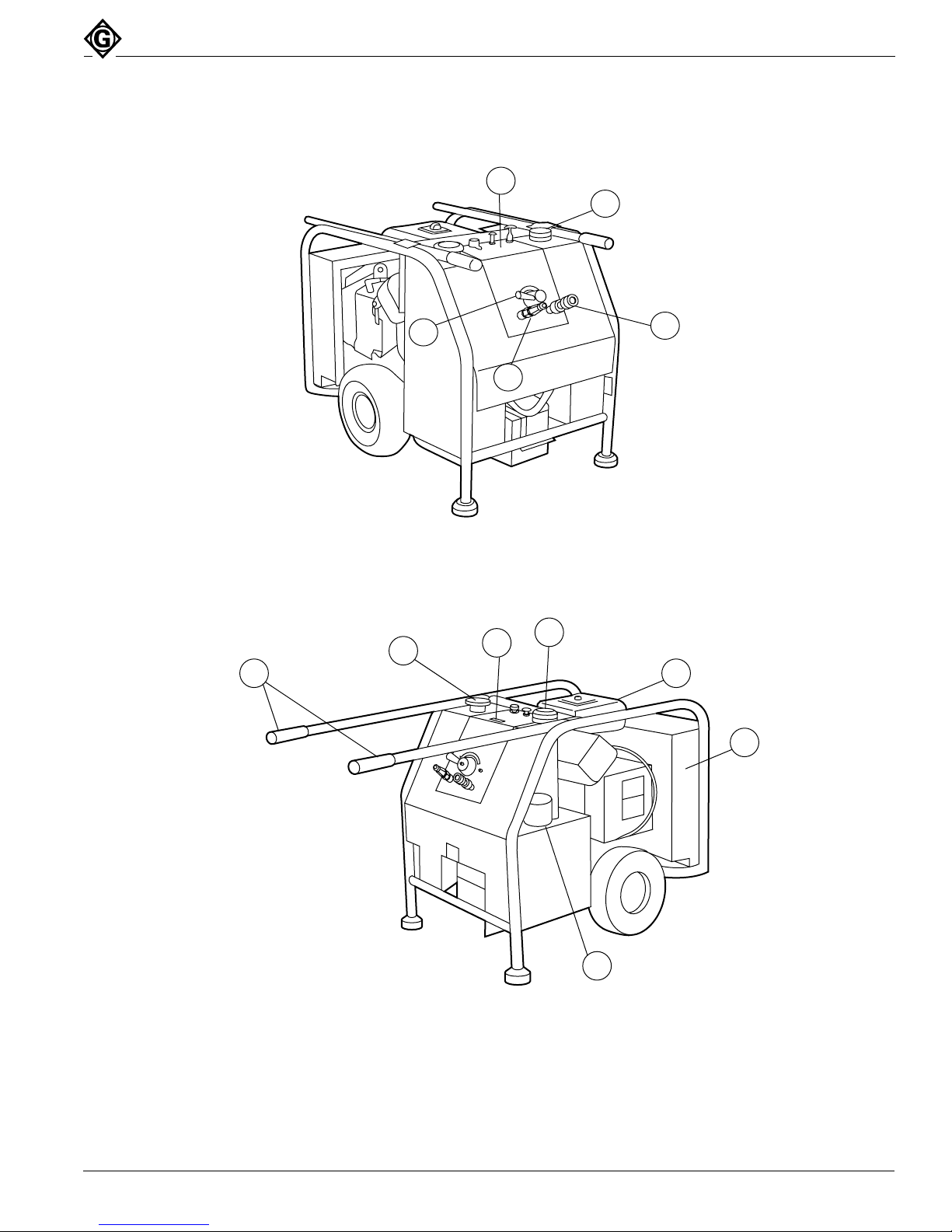
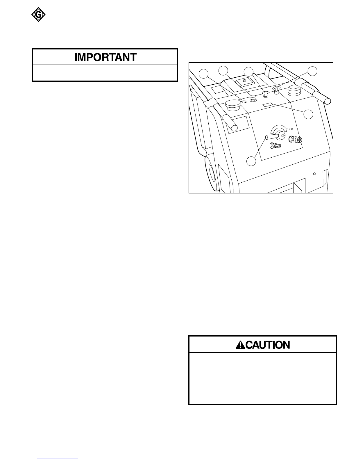
Figure 4
Power Unit Controls
Position the power unit on firm level ground.
Operation (cont’d)
Use appropriate lifting equipment. Make sure all
components used to lift this power unit are rated for
300 lbs (135 kg) and are securely attached between
the power unit and lifting equipment. Inadequate
components may fail and cause the power unit to
fall, resulting in injury or property damage.
Pre-Start
1. Check engine oil level. Refer to engine Operating
and Maintenance Instructions for correct oil type
and checking instructions.
2. Check fuel level. Refer to engine Operating and
Maintenance Instructions for fuel recommendations.
3. Check hydraulic reservoir oil level. Fill to FULL mark
on dipstick. See Maintenance. See Recommended
Hydraulic Fluids for correct hydraulic fluid.
4. Verify that all current maintenance has been per-
formed on the power unit. See Maintenance.
5. Connect the tool hoses and tool to the power unit.
See Hose Connections.
Starting the Power Unit (See Figure 4)
1. Move the flow ON / OFF lever (1) to the OFF
position.
2. Pull out the choke knob (2).
Note: A warm engine requires less choking than a cold
engine.
3.
Pull throttle T-handle (3) out to the fully open posi-
tion. Rotate T-handle clockwise to lock in position
and counterclockwise to unlock from position.
4. Move switch (4) to the ON position.
5. Depress starter button (5) to start engine.
Note: The best starter life is provided by using short
starting cycles of several seconds. Prolonged
cranking, more than 15 seconds per minute, can
damage the starter motor.
6. After the engine has started, reduce engine RPM.
Slowly open choke.
7. Move flow ON / OFF lever (1) to the ON position.
8. It is recommended that the power unit be allowed to
run (idle) for a few minutes to warm the hydraulic
reservoir fluid. Actuating the tool intermittently will
reduce the time required to warm the fluid to an
efficient operating temperature.
9. Using the engine throttle T-handle (1), adjust the
engine RPM to obtain the rated hydraulic oil flow,
5 to 8 GPM. See flow meter (6). Lock the T-handle
throttle in position. DO NOT EXCEED THE MAXI-
MUM ALLOWABLE FLOW RATE FOR THE TOOL
BEING USED WITH THE POWER UNIT. Exceeding
the tool’s maximum flow rate could cause tool
failure and personal injury. See your tool operator’s
manual for proper flow rate.
Stopping the Power Unit (See Figure 4)
1. Move the flow ON/OFF lever (1) to the OFF
position. Idle the power unit engine for a few
moments. Move switch (4) to the OFF position.
2. Disconnect the tool hoses from the power unit.
See Hose Connections.
Retractable Handles
The handles on the power unit can be extended when
transporting the power unit or retracted for convenience
when connecting/disconnecting tool hoses, starting
power unit, etc. To use the handles in the extended
position for transport, pull the handles fully out. Rotate
the handles, locking the pins on the handles into the
slots in the cover of the power unit.
Lifting the Power Unit
Stop the power unit engine before lifting. Take care
when attaching the lifting device (chain, strap, etc.) so
as not to damage the power unit.