H8508-1 Impact Wrench
Greenlee / A Textron Company 4455 Boeing Dr. • Rockford, IL 61109-2988 USA • 815-397-7070
5
Disassembly
Complete disassembly of the tool is not recommended.
If a complete overhaul is necessary, return the tool to
your nearest Greenlee Utility Authorized Service Center.
The disassembly procedure is divided into sections of
the tool. Disassemble only the section(s) necessary to
complete the repair.
Disassemble the tool on a at, clean surface. Take care
not to lose or damage any parts that may fall free during
disassembly.
In order to simplify the disassembly and assembly
instructions, refer to “Tool Orientation” below to
identify the sides and ends of the tool.
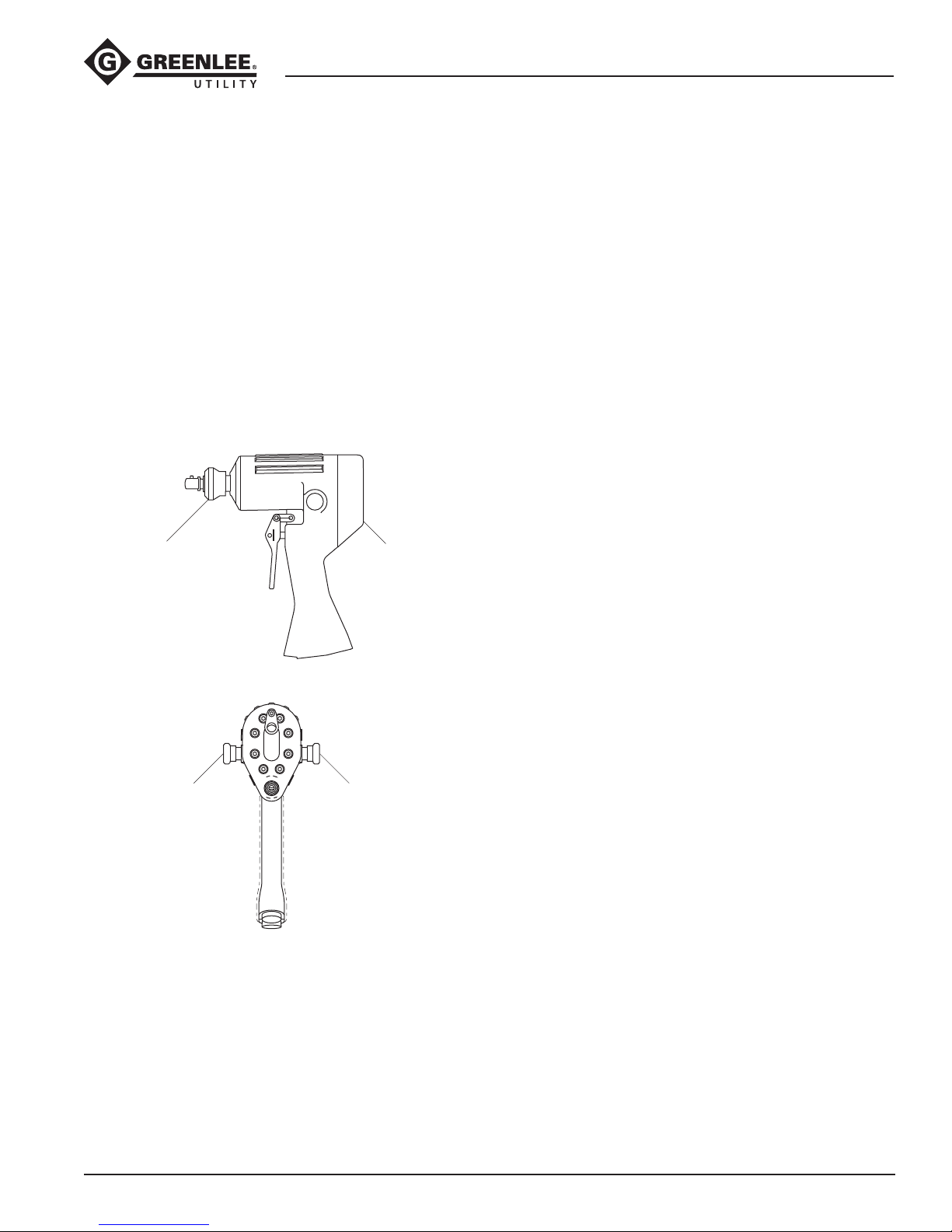
Tool Orientation
Quick-Change Chuck
1. Remove adapter (61) from retaining sleeve (50).
Note: To prevent the loss of any steel balls, perform
the next step over a clean, empty container.
2. Slide the thrust ring (52) back to expose thrust ring
lock (51). Remove thrust ring lock, thrust ring, and
spring (53). Slide the retaining sleeve off of the anvil
(49) and remove two steel balls (54).
Hammer Case Components
1. Using a wrench on the ats of the hammer case cap
(55), unscrew and remove the cap.
2. Remove the anvil (49), hammer frame (46), hammer
(47), and hammer pin (48).
3. Remove spacer (45), thrust bearing (43), and thrust
washers (44) from hammer case cavity.
Motor
1. Remove cap screws (16) and remove motor cap (6)
from handle (1). Remove gasket (15). Remove dowel
pins (14).
2. Pull idler shaft (13) with gear (10) from handle.
Remove gear from idler shaft. Remove the drive pin
(12) and retaining clip (11) from idler shaft.
3. Remove retaining ring (11), gear (10), and Woodruff
key (9) from drive shaft (8). Push drive shaft toward
hammer case end and remove it from the handle.
Trigger and Super Spool™
1. Remove roll pin (42) from trigger spool (29) by
pressing or tapping it out with a hammer and punch.
Note: Support trigger (41) to prevent bending the
trigger spool (29).
2. Remove washer (39), spring (38), retaining ring (37),
and washer (36). Push the trigger spool (29) out of
the handle (toward the front of the tool).
3. Remove the retaining ring (33).
Note: Perform Step 4 over an empty container to
catch the steel ball (32) when it falls free.
4. Remove Super Spool (31) and O-ring (34).
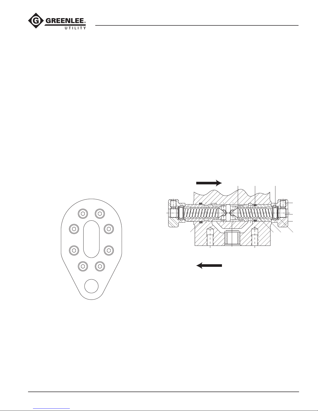
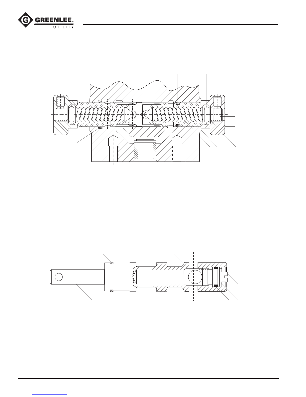
Reversing Spool
1. Loosen and remove cap (24) on left side of tool and
pull the reversing spool (19) out the right side of
tool.
Note: Attempting to push the reversing spool the
opposite way through the bore will damage the
O-rings and could allow particles of O-ring to get
into the motor.
2. Remove plug (22), spring (21), and poppet (20).
3. Repeat Step 2 for the right side of reversing
spool (19).
Left Side Right Side
C
O
Front End
(hammer case end)
Back End
(motor cap end)