Greenlee MPM-120 User manual

MICROPROCESSOR-
CONTROLLED PHASE MONITORS
MONITORES DE FASE
CONTROLADOS POR
MICROPROCESADOR
CONTROLEURS DE
PHASE COMMANDES
PAR MICROPROCESSEUR
999 3823.5 © 2000 Greenlee Textron IM 1498 10/00
INSTRUCTION MANUAL
INSTRUCTION MANUAL
MANUAL DE INSTRUCCIONES
MANUEL D’INSTRUCTIONS
789
10 11 12
COPPER,60/75°C WIRE ONLY
FREQ. SHIFT
UNDER
UNBAL
OVER
PHASE SHIFT/REV
MODE
AUTO/
RESET
MEMORY MANUAL
TMG
ØBØA ØC
123456
NORMAL
TIME
DELAY VOLTAGE
ADJ.
654321
7 8 9 101112
Read and understand all of the instructions and safety information
in this manual before operating or servicing this tool.
Lea y entienda todas las instrucciones y la información sobre
seguridad que aparecen en este manual, antes de manejar estas
herramientas o darles mantenimiento.
Lire attentivement et bien comprendre toutes les instructions et
les informations sur la sécurité de ce manuel avant d‘utiliser ou
de procéder à l‘entretien de cet outil.
MPM-120/230/380/440/575

2
KEEP THIS MANUAL
Description
Greenlee Microprocessor-Controlled Phase Monitors are intended to protect fixed
equipment from the following conditions: Under-voltage, over-voltage, phase reversal,
phase shift, phase loss, phase unbalance, frequency shift and regeneration. They have
DPDT (double pole, double throw) output contacts for connection to equipment
controller or to an alarm. When the phase monitor detects that the power supplied by
the circuit is outside of the specified tolerances, it opens the NO contacts and closes
the NC contacts.
Red LEDs indicate fault conditions to simplify troubleshooting; a green LED indicates
that the power provided is within the specified tolerances after a fault is cleared.
Greenlee offers several models of microprocessor-controlled phase monitor: MPM-120,
MPM-230, MPM-380, MPM-440, and MPM-575. The digits in the catalog number
signify the corresponding nominal circuit voltage.
Safety
Safety is essential in the use and maintenance of Greenlee tools and equipment. This
instruction manual and any markings on the tool provide information for avoiding
hazards and unsafe practices related to the use of this tool. Observe all of the safety
information provided.
Purpose
This instruction manual is intended to familiarize all personnel with the safe operation
and maintenance procedures for the following Greenlee Microprocessor-Controlled
Phase Monitors:
MPM-120 MPM-440
MPM-230 MPM-575
MPM-380
Keep this manual available to all personnel.
Replacement manuals are available upon request at no charge.
Greenlee and are registered trademarks of Greenlee Textron.

MPM-120/230/380/440/575
3
Important Safety Information
Read and understand this material before operating
or servicing this equipment. Failure to understand
how to safely operate this tool can result in an
accident causing serious injury or death.
This symbol is used to call your attention to hazards or unsafe practices
which could result in an injury or property damage. The signal word,
defined below, indicates the severity of the hazard. The message after the
signal word provides information for preventing or avoiding the hazard.
SAFETY ALERT SYMBOL
Immediate hazards which, if not avoided, WILL result in severe injury or death.
Hazards which, if not avoided, COULD result in severe injury or death.
Hazards or unsafe practices which, if not avoided, MAY result in injury or
property damage.

4
Important Safety Information (cont’d)
Electric shock hazard:
Contact with live circuits can result in severe injury
or death.
Electric shock and fire hazard:
• Do not expose this unit to rain or moisture.
• Do not use the unit if it is wet or damaged.
• Use this unit for the manufacturer’s intended purpose only, as described
in this manual. Any other use can impair the protection provided by the
unit.
Failure to observe these warnings can result in severe injury or death.
Electric shock hazard:
Shut off and lock out power before installing this
device.

MPM-120/230/380/440/575
5
Electric shock hazard:
Do not apply more than the rated voltage between any two input
terminals, or between any input terminal and earth ground.
Failure to observe this warning can result in severe injury or death.
Do not operate with the case open.
Failure to observe this warning can result in severe injury or death.
• Do not attempt to repair this unit. It contains no user-serviceable parts.
• Do not expose the unit to extremes in temperature or high humidity. See
Specifications.
Failure to observe these precautions can result in injury and can damage
the unit.
Important Safety Information (cont’d)

6
Identification
1. Input Terminals
Connect the three-phase circuit to these terminals
2. Output Terminals
Connect the control for the protected machine, or the alarm, to these terminals
3. Fault LEDs
One of these illuminates to indicate the first fault detected by the microprocessor
4. Normal LED
This illuminates to Indicate that the power from the three-phase circuit is within
the specified tolerances
5. Time Delay Adjustment
Use this to set the amount of delay for energizing the output relay after power is
determined to be within specified tolerances. (See Specifications for other fixed
time delays in the unit)
6. Voltage Adjustment
Use this to select the nominal circuit voltage
7. Mode Selector
Use this to select Manual,
Auto/Reset, or Memory
mode. These modes are
explained under Features.
8. Wiring Diagrams
Shows the alarm (de-
energized) state of the
DPDT output relay
789
10 11 12
COPPER,60/75°C WIRE ONLY
FREQ. SHIFT
UNDER
UNBAL
OVER
PHASE SHIFT/REV
MODE
AUTO/
RESET
MEMORY MANUAL
TMG
ØBØAØC
123456
NORMAL
TIME
DELAY VOLTAGE
ADJ.
654321
7 8 9 101112
3
45
6
7
1
8
2

MPM-120/230/380/440/575
7
Features
Greenlee Microprocessor-Controlled Phase Monitors include the following
features:
•A microprocessor, which continually monitors the input circuit for faults in
the following order: Phase Reversal, Phase Shift and Phase Loss, Phase
Unbalance and Frequency Shift, Undervoltage and Overvoltage. Although the
circuit may have more than one fault at a time, only one Fault Indicator LED
will be illuminated at a time.
•A Time Delay Adjustment that allows the user to select the amount of time
that occurs between these two events: (1) The moment that the microproces-
sor senses that the input power is normal and (2) the moment that the
microprocessor changes the state of the contacts (opening the NC contacts
and closing the NO contacts).
•A Voltage Adjustment that allows the user to select the nominal circuit
voltage.
•Three operating modes:
Auto/Reset:
When the phase monitor senses that the input power is normal, this mode
automatically changes the state of the contacts and resets the fault
indicator LED.
Manual:
When the phase monitor senses that the input power is normal, this mode
does not change the state of the contacts or reset the fault indicator LED.
The user must temporarily set the mode selector to Auto/Reset until the
phase monitor returns to normal.
Memory:
When the phase monitor senses that the input power is normal, this
mode automatically changes the state of the contacts but does not reset
the fault indicator LED. The user must temporarily set the mode selector to
Auto/Reset until the Fault Indicator LED is not illuminated.
8
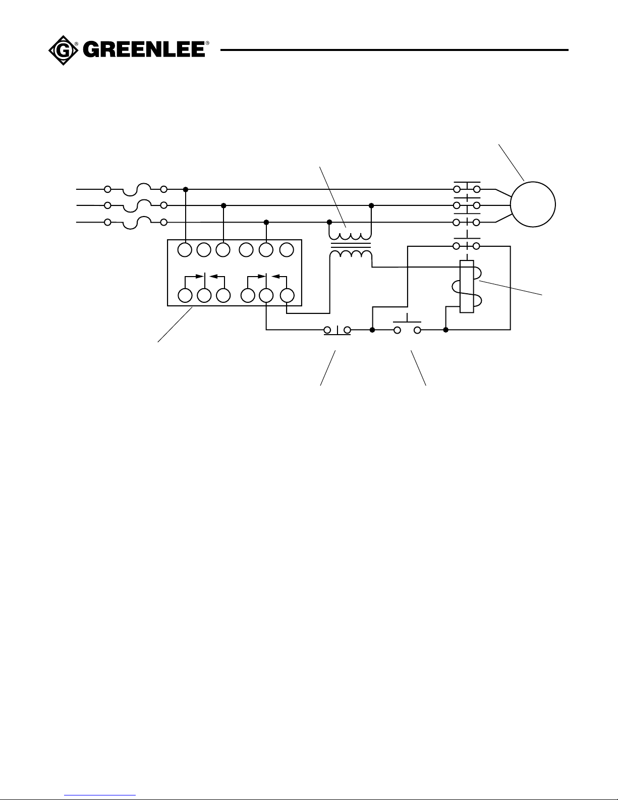
Typical Wiring Diagram
M
A
B
C
7 8 9 10 11 12
1 2 3 4 5 6
STOP START
1
32
4
5
6
1. Microprocessor-Controlled Phase Monitors
2. Start Pushbutton
3. Stop Pushbutton
4. Contactor or Motor Starter
5. Motor or other load
6. Control Transformer

MPM-120/230/380/440/575
9
Installation and Connection
1. Mount the microprocessor-controlled phase monitor in, on or near the control panel. If
the location is wet or dusty, mount the device inside a NEMA-4 or NEMA-12 enclosure.
Note: The phase monitor has four mounting holes that measure approximately 3 mm
(0.125") in diameter and 7 mm (0.25") in depth. Apply a maximum of 2.25 Newton-
meters (20 inch-pounds) of torque to the fasteners (purchased separately) when
mounting the phase monitor.
2. Use a voltmeter to determine the nominal voltage on the circuit. Set the Voltage
Adjustment to the corresponding voltage level.
3. Use a phase sequence indicator to determine the A, B and C phases.
4. Shut off and lock out power.
5. Set up the phase monitor as follows:
a) Set the Mode Selector to Auto/Reset.
b) Set the Time Delay to the shortest time delay setting.
c) Connect the power circuit to the phase monitor’s Input Contacts: Connect phase A
to Input Terminal 1, phase B to Input Terminal 3, and phase C to Input Terminal 5.
•For WYE (Y) electrical systems, connections to neutral are not required.
•Do not connect the outputs until Step 8.
6. Apply power. The microprocessor will begin to monitor the power provided by the input
circuit. The red LEDs will flash in sequence.
•If all of the red LEDs stop flashing and the green LED begins flashing, the power
provided by the circuit is within specified tolerances. The green LED will flash for the
duration of the selected time delay. Then it will stop flashing and remain on.
•If one red LED remains illuminated, see Fault Indicators and Troubleshooting.
7. After clearing any faults, shut off and lock out power.
8. Use the wiring diagrams provided on the unit to connect the equipment control or
alarm to the phase monitor’s Output Terminals. Typically the equipment control is
connected to the NO contacts while an alarm is connected to the NC contacts.
9. Set the Time Delay Adjustment and Mode Selector to the preferred settings.
10. Apply power.

10
Fault Indicators and Troubleshooting
•Frequency Shift: The input frequency is too high or too low.
•Under: The input voltage is too low for the setting of the Voltage Adjustment.
Troubleshoot the circuit to determine if the setting is incorrect or there is a
problem with the line voltage. See Installation and Connection section for
instructions to determine correct setting for Voltage Adjustment.
•Unbal: The voltage among the three phases is unbalanced. This could be due
to (a) an excessive load on either phase A, B or C, or (b) a high-resistance
load (such as a poor connection, shorted motor winding, pitted or burnt
starter contacts).
To calculate the amount of phase unbalance:
(1) Measure the voltage at each phase.
Example: Phase A to B = 202 Phase A to C = 220 Phase B to C: 214
(2) Find the average voltage.
Example: (205 + 220 + 214) divided by 3 = 636 / 3 = 213
(3) Find the maximum deviation from the average.
Example: Phase A to B: 213 - 205 = 8 Phase A to C = 220 - 213 = 7
Phase B to C = 214 - 213 = 1
(4) Divide the maximum deviation by the average.
Multiply that result by 100 to get a percentage.
Example: 8 / 213 = 0.038 x 100 = 3.8% Unbalance
•Over: The input voltage is too high for the setting of the Voltage Adjustment.
Troubleshoot the circuit to determine if the setting is incorrect or there is a
problem with the line voltage. See Installation and Connection section for
instructions to determine correct setting for Voltage Adjustment.
•Phase Shift/Rev: This could have either of the following causes:
-
No input from phase B (possibly due to an open fuse, poor connection, etc.).
Troubleshoot the circuit.
- Two of the phases are reversed. Shut off and lock out power, switch any two
leads, then apply power.
•No Fault Indicator LEDs Illuminated: No input from phase A or C (possibly
due to an open fuse, poor connection, etc.). Troubleshoot the circuit.
This manual suits for next models
4
Table of contents
Languages:


