855 Smart Bender®
Greenlee / A Textron Company 4455 Boeing Dr. • Rockford, IL 61109-2988 USA • 815-397-7070
9
Maintenance (cont’d)
1-1/2" to 2" Roller Support
1. Disconnect the bender from the power source.
2. Remove the 1-1/2" to 2" shoe (refer to “Changing
Shoes” in this section of the manual).
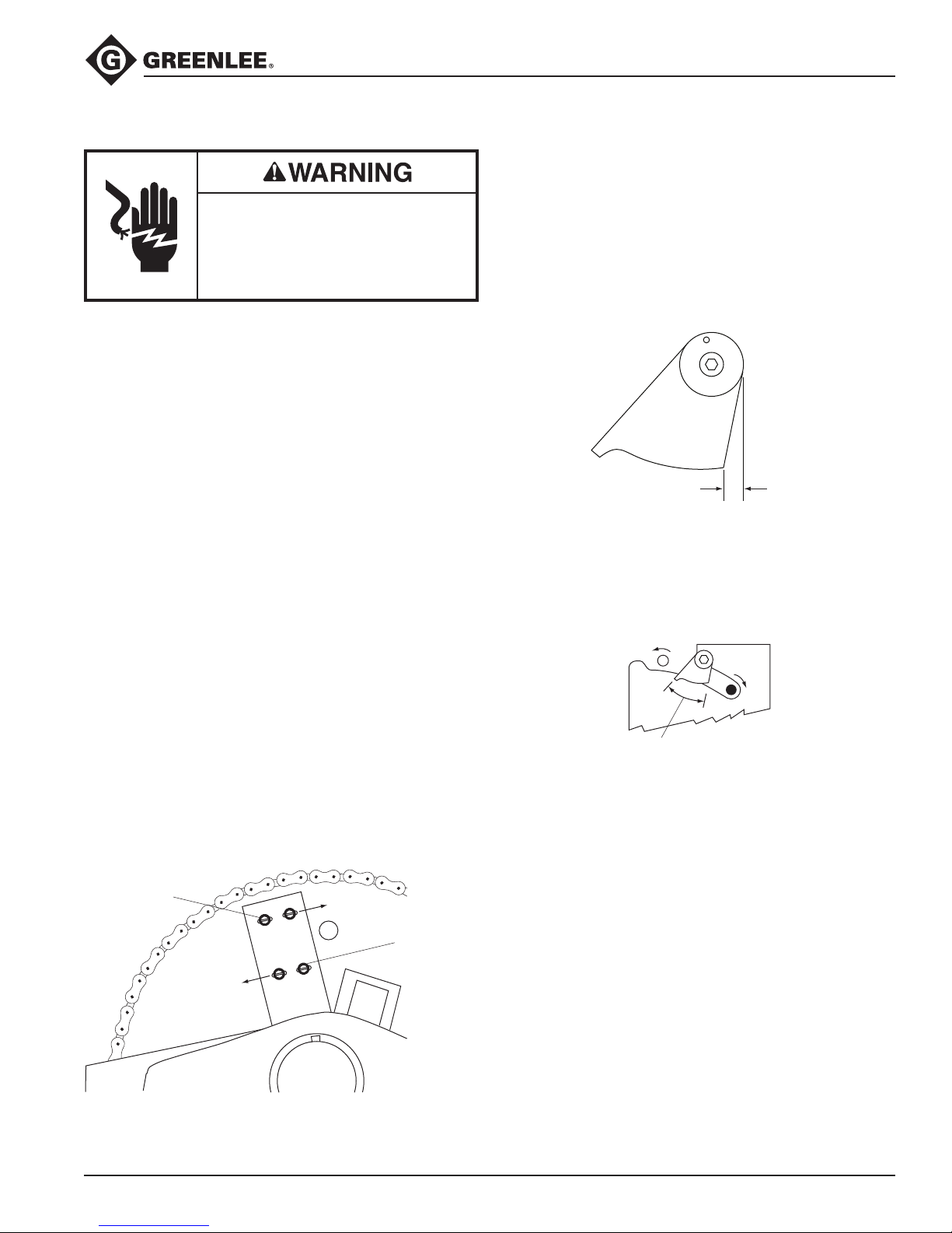
3. Refer to the “1-1/2" to 2" Roller Support Unit
Exploded View.” Use a pair of needle-nose pliers to
disconnect the springs (104) from the holes in the
side of the bender frame beneath the roller support
unit.
4. Refer to the “Main Exploded View.” Remove the
squeeze adjustment arm screw (97) and arm (74).
5. Remove the three button head cap screws (96) and
adapter sleeve (92).
6. Place one hand under the support arms (71) to
support the weight of the roller support unit.
Remove the eccentric shaft (91).
Note: You may need to rotate the eccentric shaft to
remove it.
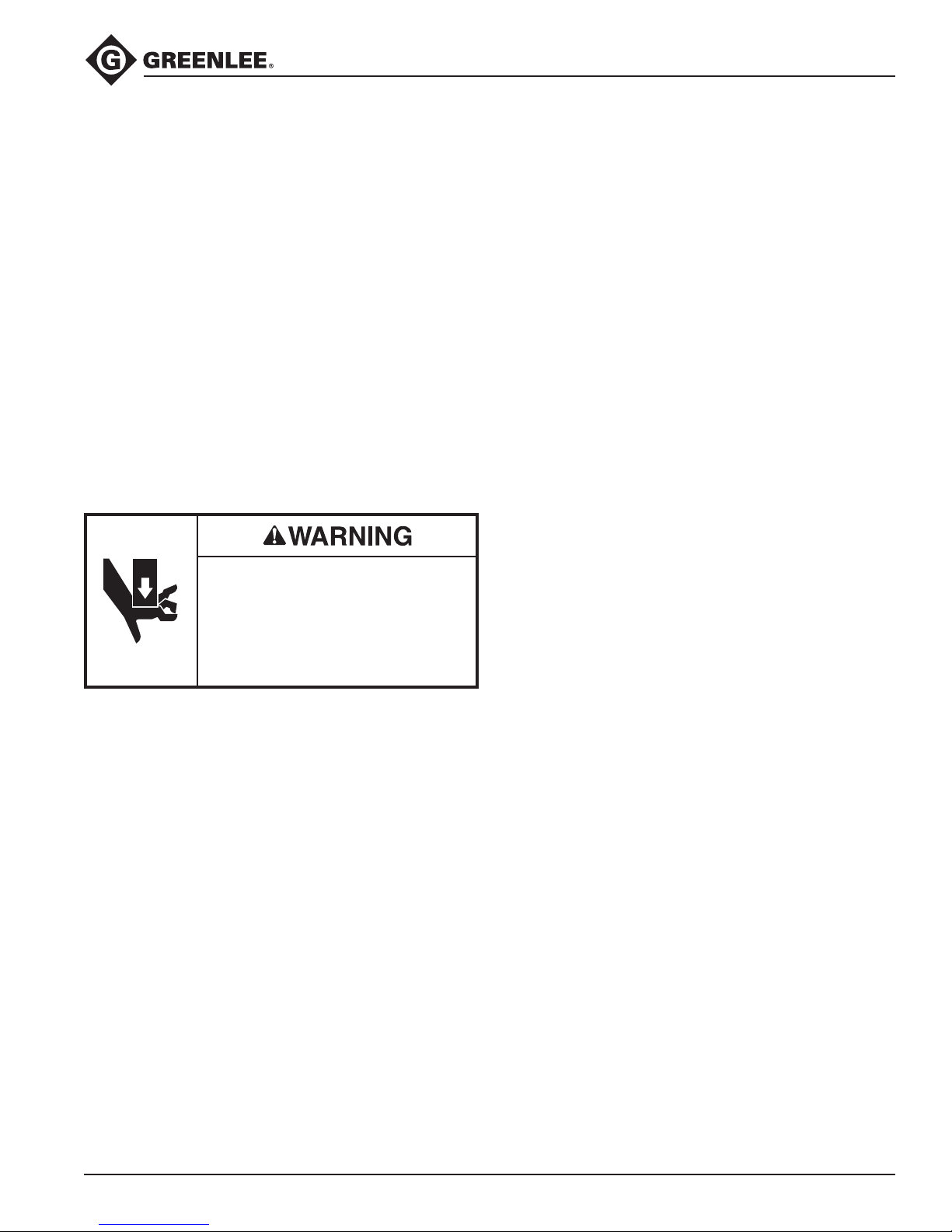
Pinch points:
Keep hands away from bending
shoe, rollers, and conduit when
bender is in use.
Failure to observe this warning could
result in severe injury or death.
7. Lift the roller support subassembly to the left and
upward.
8. On the 1-1/2" roller group:
Loosen the sleeve set screw (98) and remove the
1-1/2" pivot roller shaft (86) with grip (90). Remove
the sleeve (87).
Remove two hex head screws (93). Remove the
outer roller plate (75).
Remove the tail roller (84).
Remove all components of the split roller
assembly.
9. On the 2" roller group:
Loosen the sleeve set screw (98) and press out
the 2" pivot shaft (88). Remove the sleeve (89).
Remove the hex head screw (93). Remove one
retaining ring (95) from the tail roller shaft (83).
Remove the outer roller plate (76).
Remove the tail roller (82) and center roller (85).
Remove all components of the split roller
assembly.
•
•
•
•
•
•
•
•
10. Clean off all of the grease and dirt.
11. Inspect each item. Replace any worn, damaged,
or missing items.
12. Lubricate all working surfaces with a high-quality
grease.
13. Replace all components in reverse order, noting the
following:
On both roller groups: To ease the assembly of
the split roller subassemblies, begin by slipping
the O-rings onto the side plates. Assemble the
split roller subassemblies as shown, and then slip
the O-rings into their correct positions.
On the 2" roller group only: After replacing any
split roller components, add or remove shim
washers (99, 119, or 150) as needed.
On the 1-1/2" roller group: Install the two
Belleville washers (100) so that the inside diam-
eters contact each other.
Use Loctite®271 on the two hex head screws (93).
Torque to 55 Nm to 61 Nm (40 ft-lb to 45 ft-lb).
14. Position the roller support arms (71) as shown.
Assemble the roller groups to the support arms.
15. Reinstall the roller support unit to the bender. Keep
one hand under the support arms so they do not
drop completely below the set screw (107).
16. Insert the eccentric shaft (91).
Note: You may need to rotate the eccentric shaft to
get it to seat completely.
17. Install the adapter sleeve (92) and three button head
cap screws (96).
18. Install the adjustment arm (74) and adjustment arm
screw (97).
19. Attach the springs (104) to the holes in the side of
the bender frame beneath the roller support unit.
20. Put the bender in the horizontal bending position.
Adjust the set screw (107), if necessary, so that the
support arms (71) are centered between the front
and back plates. Engage and disengage the roller
support unit to be sure that it moves freely.
•
•
•
•