Greenlee Textron / Subsidiary of Textron Inc. 34455 Boeing Dr., Rockford, IL 61109-2988 815/397-7070
853 Quad Bender™
IMPORTANT SAFETY INFORMATION
This symbol is used to call your attention to hazards
or unsafe practices which could result in an injury
or property damage. The signal word, defined below,
indicates the severity of the hazard. The message after
the signal word provides information for preventing or
avoiding the hazard.
Hazards or unsafe practices which, if not avoided,
MAY result in injury or property damage.
Hazards which, if not avoided, COULD result in severe
injury or death.
Immediate hazards which, if not avoided, WILL result
in severe injury or death.
SAFETY
ALERT
SYMBOL
Read and understand all of the
instructions and safety information
in this manual before operating or
servicing this tool.
Failure to observe this warning will
result in severe injury or death.
• Do not expose to rain.
• Do not use in wet or damp
locations.
Failure to observe these warnings
can result in severe injury or death.
Wear eye protection when operating
or servicing this tool.
Failure to wear eye protection can
result in serious eye injury from
flying debris.
Do not remove guards.
Failure to observe this warning can
result in severe injury or death.
Do not use this tool in a hazardous
environment. Hazards include
flammable liquids, gases, or other
materials. Using this tool in a
hazardous environment can result in
a fire or explosion.
Failure to observe this warning will
result in severe injury or death.
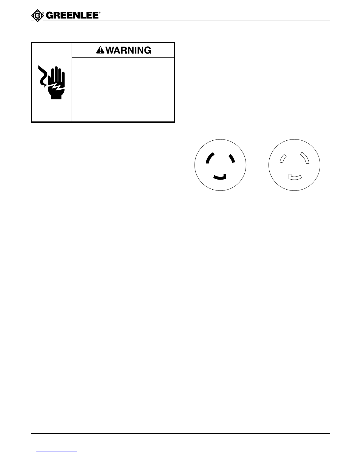
Electric shock hazard:
• Connect the power cord to a 120
volt, 20 amp receptacle on a
ground fault protected circuit only.
See Grounding Instructions.
• Do not modify the power cord or
plug.
• Inspect the power cord before
use. Repair or replace the cord if
damaged.
• Disconnect from power before
servicing.
Failure to observe this warning can
result in severe injury or death.
Wear protective footwear when
operating or servicing this tool.
Failure to observe this warning can
result in severe injury.