Greenlee Textron / Subsidiary of Textron Inc. 94455 Boeing Dr., Rockford, IL 61109-2988 815/397-7070
855 Smart Bender™
Operation —Standard Pendant
Set the type and size of conduit you will be bending
with the rotary selector switches located on the side
of the bender.
Failure to do so may result in the shoe rotating the
opposite direction than expected.
Bend Key: runs the shoe in the direction to bend the
conduit according to which conduit size has been
selected by the rotary size selector switch. The BEND
key functions only while it is pressed. The BEND key
ceases to function once it reaches the maximum shoe
travel or an angle stored in memory.
Jog Key: runs the shoe in the direction to bend the
conduit according to which conduit size has been
selected by the rotary size selector switch in 1/2-degree
increments. The JOG key functions any time it is
pressed until the maximum shoe travel is reached.
Unload Key: runs the shoe backwards according to
which conduit size has been selected by the rotary size
selector switch. The UNLOAD key functions when it is
pressed unless the roller support locking cam is locked
in position.
Note: The shoes can rotate a restricted amount in the
bend direction. When the maximum has been reached, the
BEND and JOG keys will not function. Use the UNLOAD
key to rotate the shoes to the proper load position.
Angle Select ▲: is used to set the desired bend angle
into memory. Pressing it for a moment increases the
present angle in memory 1 degree at a time. Holding it
down rapidly advances the memory angle.
Angle Select ▼: functions the same as the ANGLE
SELECT UP key except it decreases the angle.
Clear Key: sets the display to 00 and eliminates any
angle from memory. It will not reset the actual present
bend angle to zero.
CONDUIT SIZE
CONDUIT TYPE
DECAL NO. 500 8896.7
1/2
3/4
11-1/4
1-1/2
2
DECAL NO. 500 1487.0
RIGID ALUM
PVC
IMC
EMT
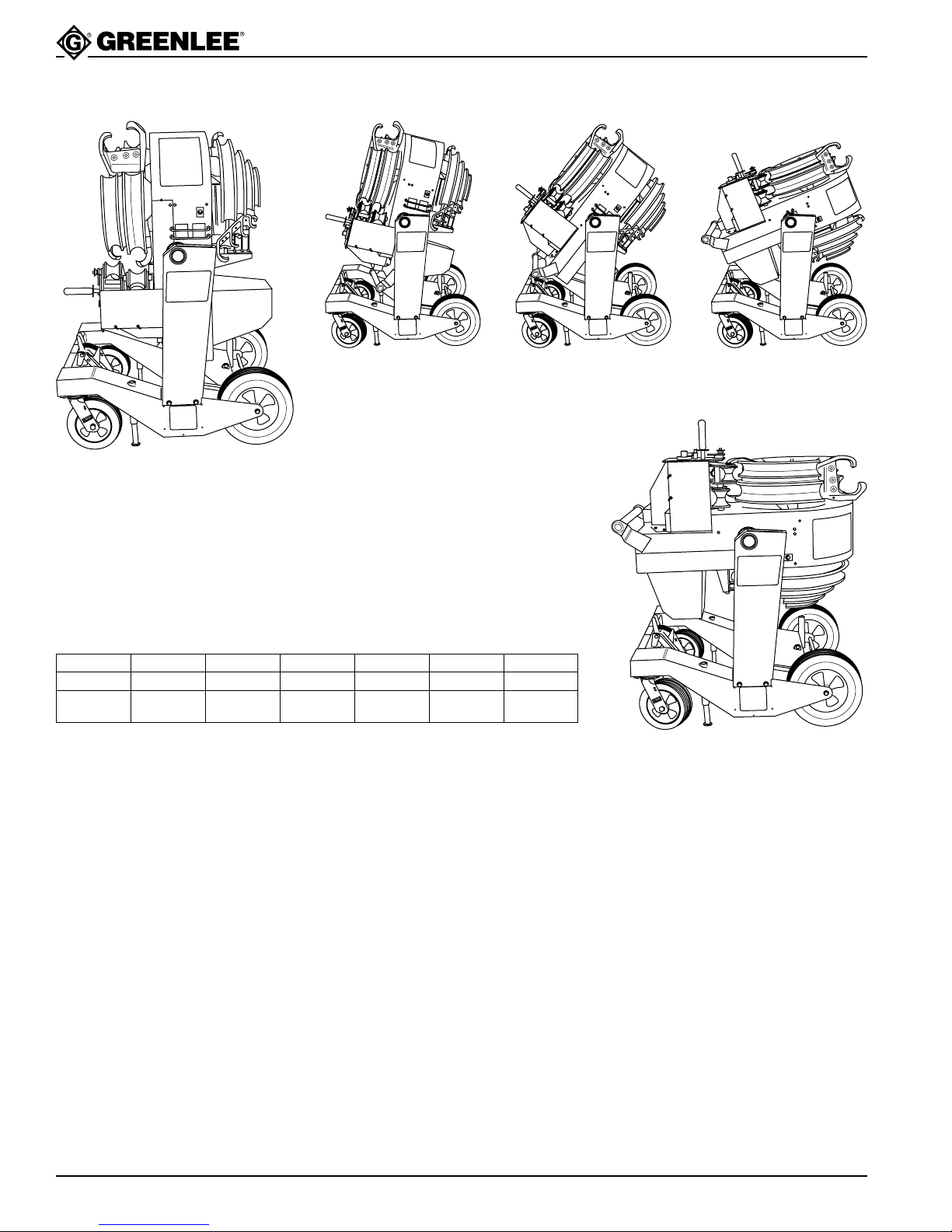
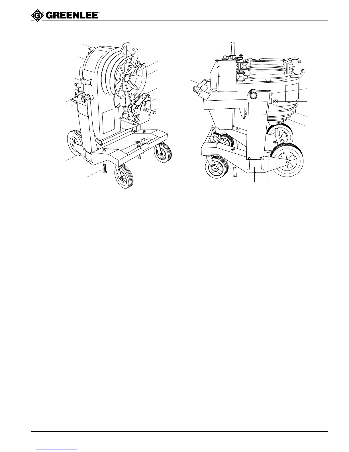
Use lifting eyes for hoisting
Lift only with bending head in a horizontal position
with the 1-1/2" and2" side up
Display: shows the actual angle the conduit has been
bent in degrees. Counting does not start until the
conduit actually starts to bend. If an angle is stored in
memory, the display shows the stored angle at all times
except while the BEND, JOG, or UNLOAD keys are
depressed and for about 2 seconds after they are
released. The display will not show angles greater than
99 or less than 0.
Upon power-up the display will show H., which indicates
that the home position must be set on the bender before
installing conduit. Press UNLOAD until the shoe hook
for the size and type of conduit selected is at the bottom
(5 o’clock position). Press BEND until the pendant
display changes from H. and starts counting. Then
press UNLOAD until the shoe rotates backwards and
stops. This is the proper load position for the selected
size and type of conduit and home position is now set.
The display will show H. each time there is a change in
conduit type setting, a change in conduit size to the
other shoe, and when power to the bender has been
interrupted.
Accuracy Adjust Mode: due to variations in conduit,
you may notice the bender consistently over or under
bending a particular size and type of conduit. The
accuracy adjustment mode allows programming correc-
tions for over and under bending conduit. Minus 9 to
plus 9 degree adjustments can be made for each size
and type of conduit. Press and hold CLEAR, then press
and hold BEND until Pr is displayed. Release controls
and adjust the degrees of bend by pressing the ANGLE
SELECT up and down controls. ANGLE SELECT UP
increases and ANGLE SELECT DOWN decreases the
bend angle for the size and type of conduit selected by
the rotary selector switches. CLEAR resets the adjust
angle to zero. Any adjust angle may be displayed by
setting the rotary selector switches to the desired size
and type of conduit. Press BEND to save the adjust
angle and exit the Adjust mode. Only changes to the
last displayed value will be saved. Changes saved are
to permanent memory in the bender and can only be
changed by reprogramming. The pendant will display
oP for two seconds when the bender returns to the
normal operating mode.
BEND
JOG
UNLOAD
ANGLE
SELECT
ANGLE
SELECT
CLEAR