Grizzly G3358 User manual

WARNING: NO PORTION OF THIS MANUAL MAY BE REPRODUCED IN ANY SHAPE
OR FORM WITHOUT THE WRITTEN APPROVAL OF GRIZZLY INDUSTRIAL, INC.
MODEL G3358
MILLING/DRILLING MACHINE
OWNER'S MANUAL

4HISMANUALPROVIDESCRITICALSAFETYINSTRUCTIONSONTHEPROPERSETUP
OPERATIONMAINTENANCEANDSERVICEOFTHISMACHINEEQUIPMENT
&AILURETOREADUNDERSTANDANDFOLLOWTHEINSTRUCTIONSGIVENINTHIS
MANUALMAYRESULTINSERIOUSPERSONALINJURYINCLUDINGAMPUTATION
ELECTROCUTIONORDEATH
4HEOWNEROFTHISMACHINEEQUIPMENTISSOLELYRESPONSIBLEFORITS
SAFEUSE4HISRESPONSIBILITYINCLUDESBUTISNOTLIMITEDTOPROPER
INSTALLATIONINASAFEENVIRONMENTPERSONNELTRAININGANDUSAGE
AUTHORIZATIONPROPERINSPECTIONANDMAINTENANCEMANUALAVAILABILITY
ANDCOMPREHENSIONAPPLICATIONOFSAFETYDEVICESBLADECUTTERINTEG
RITYANDTHEUSAGEOFPERSONALPROTECTIVEEQUIPMENT
4HEMANUFACTURERWILLNOTBEHELDLIABLEFORINJURYORPROPERTYDAMAGE
FROMNEGLIGENCEIMPROPERTRAININGMACHINEMODIFICATIONSORMISUSE
3OMEDUSTCREATEDBYPOWERSANDINGSAWINGGRINDINGDRILLINGAND
OTHERCONSTRUCTIONACTIVITIESCONTAINSCHEMICALSKNOWNTOTHE3TATE
OF#ALIFORNIATOCAUSECANCERBIRTHDEFECTSOROTHERREPRODUCTIVE
HARM3OMEEXAMPLESOFTHESECHEMICALSARE
s ,EADFROMLEADBASEDPAINTS
s #RYSTALLINESILICAFROMBRICKSCEMENTANDOTHERMASONRYPRODUCTS
s !RSENICANDCHROMIUMFROMCHEMICALLYTREATEDLUMBER
9OURRISKFROMTHESEEXPOSURESVARIESDEPENDINGONHOWOFTENYOU
DOTHISTYPEOFWORK4OREDUCEYOUREXPOSURETOTHESECHEMICALS
7ORKINAWELLVENTILATEDAREAANDWORKWITHAPPROVEDSAFETYEQUIP
MENTSUCHASTHOSEDUSTMASKSTHATARESPECIALLYDESIGNEDTOFILTER
OUTMICROSCOPICPARTICLES

Table of Contents
INTRODUCTION............................................... 2
SECTION 1: SAFETY....................................... 7
SECTION 2: CIRCUIT REQUIREMENTS ...... 10
SECTION 3: SETUP ....................................... 11
SECTION 4: OPERATIONS ........................... 19
SECTION 5: ACCESSORIES......................... 26
SECTION 6: MAINTENANCE......................... 28
SECTION 7: SERVICE ................................... 30
SECTION 8: WIRING...................................... 35
SECTION 9: PARTS....................................... 37
WARRANTY AND RETURNS ........................ 45

Foreword
www.grizzly.com
Contact Info
Functional Overview
INTRODUCTION

Figure 1.
Identification
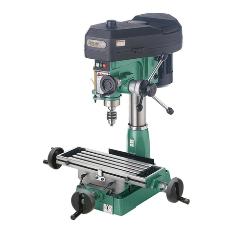
A. Directional Switch
B. Micro-Adjustment Handwheel
C. Depth Stop
D. 3" Face Mill
E. Longitudinal Stops
F. Cast Iron Base
G. Micro-Adjustment Lock Knob
H. Quill Downfeed Levers—
I. Longitudinal (X-Axis) Handwheel
J. Cross (Y-Axis) Handwheel—

The information contained herein is deemed accurate as of 5/27/2008 and represents our most recent product specifications.
Due to our ongoing improvement efforts, this information may not accurately describe items previously purchased. PAGE 1 OF 3Model G3358
MACHINE DATA
SHEET
Customer Service #: (570) 546-9663 · To Order Call: (800) 523-4777 · Fax #: (800) 438-5901
MODEL G3358 MILL / DRILL
Product Dimensions:
Weight.............................................................................................................................................................. 540 lbs.
Length/Width/Height.................................................................................................................41-1/2 x 41-1/2 x 43 in.
Foot Print (Length/Width)............................................................................................................................. 23 x 18 in.
Shipping Dimensions:
Type........................................................................................................................................................... Wood Crate
Content............................................................................................................................................................ Machine
Weight.............................................................................................................................................................. 620 lbs.
Length/Width/Height............................................................................................................................. 33 x 31 x 46 in.
Electrical:
Switch................................................................................................................................................ Forward/Reverse
Switch Voltage...................................................................................................................................................... 220V
Cord Length............................................................................................................................................................ 6 ft.
Cord Gauge....................................................................................................................................................12 gauge
Recommended Breaker Size............................................................................................................................ 10 amp
Plug.......................................................................................................................................................................... No
Motors:
Main
Type.................................................................................................................. TEFC Capacitor Start Induction
Horsepower.................................................................................................................................................2 HP
Voltage.................................................................................................................................................110/220V
Prewired......................................................................................................................................................220V
Phase........................................................................................................................................................ Single
Amps....................................................................................................................................................15.5/7.8A
Speed.................................................................................................................................................1720 RPM
Cycle..........................................................................................................................................................60 Hz
Number Of Speeds........................................................................................................................................... 1
Power Transfer ............................................................................................................................... V-Belt Drive
Bearings........................................................................................................ Shielded, Permanently Lubricated

The information contained herein is deemed accurate as of 5/27/2008 and represents our most recent product specifications.
Due to our ongoing improvement efforts, this information may not accurately describe items previously purchased. PAGE 2 OF 3Model G3358
Main Specifications:
Operation Info
Spindle Travel.............................................................................................................................................. 5 in.
Swing................................................................................................................................................... 15-7/8 in.
Longitudinal Table Travel.....................................................................................................................23-1/2 in.
Cross Table Travel....................................................................................................................................... 7 in.
Ram Travel.................................................................................................................................................12 in.
Head Travel..................................................................................................................................................5 in.
Head Swivel.......................................................................................................................................... 360 deg.
Turret Or Column Swivel.......................................................................................................................360 deg.
Max. Dist Spindle To Column.......................................................................................................................7 in.
Max. Dist Spindle To Table.................................................................................................................. 17-3/4 in.
Drilling Cap For Cast Iron.......................................................................................................................1-1/4 in.
Drilling Cap For Steel............................................................................................................................. 1-1/4 in.
No. Of Vert. Spindle Speeds........................................................................................................................... 12
Range Of Vert. Spindle Speeds................................................................................................120 - 2500 RPM
Quill Dia.................................................................................................................................................2.950 in.
Table Info
Table Length........................................................................................................................................ 28-3/4 in.
Table Width............................................................................................................................................ 8-1/4 in.
Table Thickness..................................................................................................................................... 1-7/8 in.
No. Of T Slots....................................................................................................................................................4
T Slots Width......................................................................................................................................... 0.550 in.
T Slots Height........................................................................................................................................0.850 in.
T Slots Centers...................................................................................................................................... 1-3/4 in.
Stud Size................................................................................................................................................... 3/8 in.
Spindle Info
Spindle Taper................................................................................................................................................ R-8
Spindle Sleeve Diameter..............................................................................................................................3 in.
End Milling Cap......................................................................................................................................... 3/4 in.
Face Milling Cap...........................................................................................................................................3 in.
Draw Bar Diameter..................................................................................................................................7/16 in.
Draw Bar TPI...................................................................................................................................................20
Draw Bar Length.................................................................................................................................. 15-5/8 in.
Spindle Bearings......................................................................................................................... Tapered Roller
Lead Screw Info
Lead Screw Diameter............................................................................................................................15/16 in.
Lead Screw TPI...............................................................................................................................................10
Lead Screw Length.................................................................................................................................... 32 in.
Construction
Spindle Housing Const......................................................................................................................... Cast Iron
Table Const................................................................................................................Surface Ground Cast Iron
Head Const...........................................................................................................................................Cast Iron
Column Const.......................................................................................................................................Cast Iron
Base Const........................................................................................................................................... Cast Iron
Paint.......................................................................................................................................................... Epoxy
Other
Collars Calibrated..................................................................................................................................0.001 in.
Column Dia............................................................................................................................................ 4-1/2 in.
Optional Stand..........................................................................................................................................G5944
Mobile Base..............................................................................................................................................G7314

The information contained herein is deemed accurate as of 5/27/2008 and represents our most recent product specifications.
Due to our ongoing improvement efforts, this information may not accurately describe items previously purchased. PAGE 3 OF 3Model G3358
Other Specifications:
Country Of Origin ................................................................................................................................................China
Warranty ............................................................................................................................................................ 1 Year
Serial Number Location ........................................................................................................... Label on Head Casting
Assembly Time .................................................................................................................................................. 1 hour
Features:
Clutch-Type Downfeed Mechanism
Graduations in Inches
Accessories Included:
1/2" Drill Chuck
15/16" Lock Wrench
3" Face Milling Cutter
Arbor Bolt
Inner Hexagon Wrench
R8-JT3 Tapered Bar

Safety Instructions for Machinery
!,7!93 53% (%!2).' 02/4%#4)/.
7(%./0%2!4).' -!#().%29
BVX]^cZgn cd^hZ XVc XVjhZ eZgbVcZci
]ZVg^c\adhh#
7%!2 02/0%2 !00!2%, 9D CDI
lZVgaddhZXadi]^c\!\adkZh!cZX`i^Zh!g^c\h!
dg_ZlZagni]ViXVcXViX]^cbdk^c\ eVgih#
LZVg egdiZXi^kZ ]V^g XdkZg^c\ id XdciV^c
adc\]V^gVcYlZVgcdc"ha^e[ddilZVg#
.%6%2 /0%2!4% -!#().%29 7(%.
4)2%$/25.$%24(%).&,5%.#%/&
$25'3/2!,#/(/,7ZbZciVaanVaZgi
ViVaai^bZhl]Zcgjcc^c\bVX]^cZgn#
2%!$4(%%.4)2%-!.5!,"%&/2%
34!24).'-!#().%29BVX]^cZgnegZh"
Zcih hZg^djh ^c_jgn ]VoVgYh id jcigV^cZY
jhZgh#
!,7!93 53% !.3) !002/6%$
3!&%49',!33%37(%./0%2!4).'
-!#().%29 :kZgnYVn ZnZ\aVhhZh dcan
]VkZ ^beVXi gZh^hiVci aZchZh·i]Zn VgZ
CDIhV[Zin\aVhhZh#
!,7!93 7%!2 ! .)/3( !002/6%$
2%30)2!4/2 7(%. /0%2!4).'
-!#().%29 4(!4 02/$5#%3 $534
BdhiineZhd[YjhilddY!bZiVa!ZiX#XVc
XVjhZhZkZgZgZhe^gVidgn^aacZhhZh#
&OR9OUR/WN3AFETY2EAD)NSTRUCTION
-ANUAL"EFORE/PERATINGTHIS-ACHINE
4HEPURPOSEOFSAFETYSYMBOLSISTOATTRACTYOURATTENTIONTOPOSSIBLEHAZARDOUSCONDITIONS4HIS
MANUALUSESASERIESOFSYMBOLSANDSIGNALWORDSINTENDEDTOCONVEYTHELEVELOFIMPORTANCE
OFTHESAFETYMESSAGES4HEPROGRESSIONOFSYMBOLSISDESCRIBEDBELOW2EMEMBERTHATSAFETY
MESSAGESBYTHEMSELVESDONOTELIMINATEDANGERANDARENOTASUBSTITUTEFORPROPERACCIDENT
PREVENTIONMEASURES
)NDICATESAPOTENTIALLYHAZARDOUSSITUATIONWHICHIFNOTAVOIDED
-!9RESULTINMINORORMODERATEINJURY)TMAYALSOBEUSEDTOALERT
AGAINSTUNSAFEPRACTICES
)NDICATESAPOTENTIALLYHAZARDOUSSITUATIONWHICHIFNOTAVOIDED
#/5,$RESULTINDEATHORSERIOUSINJURY
)NDICATESANIMMINENTLYHAZARDOUSSITUATIONWHICHIFNOTAVOIDED
7),,RESULTINDEATHORSERIOUSINJURY
4HISSYMBOLISUSEDTOALERTTHEUSERTOUSEFULINFORMATIONABOUT
PROPEROPERATIONOFTHEMACHINE
./4)#%
3AFETY)NSTRUCTIONSFOR-ACHINERY
3%#4)/.3!&%49

/.,9 !,,/7 42!).%$ !.$ 02/0
%2,9 350%26)3%$ 0%23/..%, 4/
/0%2!4% -!#().%29 BV`Z hjgZ
deZgVi^dc^chigjXi^dchVgZhV[ZVcYXaZVgan
jcYZghiddY#
+%%0#(),$2%.!.$6)3)4/23!7!9
@ZZe Vaa X]^aYgZc VcY k^h^idgh V hV[Z Y^h"
iVcXZ[gdbi]Zldg`VgZV#
-!+% 7/2+3(/0 #(),$02//&JhZ
eVYadX`h! bVhiZg hl^iX]Zh! VcY gZbdkZ
hiVgihl^iX]`Znh#
.%6%2 ,%!6% 7(%. -!#().% )3
25..).'IjgcedlZg/&&VcYVaadlVaa
bdk^c\eVgihid XdbZ id VXdbeaZiZhide
WZ[dgZaZVk^c\bVX]^cZjcViiZcYZY#
$/ ./4 53% ). $!.'%2/53
%.6)2/.-%.43 9D CDI jhZ bVX]^c"
Zgn ^c YVbe! lZi adXVi^dch! dg l]ZgZ Vcn
[aVbbVWaZdgcdm^djh[jbZhbVnZm^hi#
+%%07/2+!2%!#,%!.!.$7%,,
,)'(4%$8ajiiZgVcYYVg`h]VYdlhbVn
XVjhZVXX^YZcih#
53%! '2/5.$%$%84%.3)/.#/2$
2!4%$&/24(%-!#().%!-0%2!'%
<gdjcYZYXdgYh b^c^b^oZ h]dX` ]VoVgYh#
JcYZgh^oZY XdgYh XgZViZ ZmXZhh^kZ ]ZVi#
6alVnhgZeaVXZYVbV\ZYZmiZch^dcXdgYh#
!,7!93 $)3#/..%#4 &2/- 0/7%2
3/52#% "%&/2% 3%26)#).'
-!#().%29#BV`Z hjgZhl^iX]^h ^c
D;;
edh^i^dcWZ[dgZgZXdccZXi^c\#
-!).4!). -!#().%29 7)4( #!2%
@ZZeWaVYZhh]VgeVcYXaZVc[dgWZhiVcY
hV[ZhieZg[dgbVcXZ#;daadl^chigjXi^dch[dg
ajWg^XVi^c\VcYX]Vc\^c\VXXZhhdg^Zh#
-!+% 352% '5!2$3 !2% ). 0,!#%
!.$ 7/2+ #/22%#4,9 "%&/2%
53).'-!#().%29
3AFETY)NSTRUCTIONSFOR-ACHINERY
2%-/6% !$*534).' +%93 !.$
72%.#(%3BV`ZV]VW^id[X]ZX`^c\[dg
`ZnhVcYVY_jhi^c\lgZcX]ZhWZ[dgZijgc"
^c\bVX]^cZgn/.#
#(%#+ &/2 $!-!'%$ 0!243
"%&/2%53).'-!#().%298]ZX`[dg
W^cY^c\dgb^hVa^\cZYeVgih!Wgd`ZceVgih!
addhZWdaih! VcYVcn di]ZgXdcY^i^dchi]Vi
bVn ^beV^g bVX]^cZ deZgVi^dc# GZeV^g dg
gZeaVXZYVbV\ZYeVgihWZ[dgZdeZgVi^dc#
53% 2%#/--%.$%$ !##%33/2)%3
GZ[Zgidi]Z^chigjXi^dcbVcjVa[dggZXdb"
bZcYZY VXXZhhdg^Zh# >begdeZg VXXZhhd"
g^Zh^cXgZVhZg^h`d[^c_jgn#
$/ ./4 &/2#% -!#().%29 Ldg` Vi
i]ZheZZY[dgl]^X]i]ZbVX]^cZdgVXXZh"
hdgnlVhYZh^\cZY#
3%#52% 7/2+0)%#% JhZ XaVbeh dg
V k^hZ id ]daY i]Z ldg`e^ZXZ l]Zc egVXi^"
XVa# 6 hZXjgZY ldg`e^ZXZ egdiZXih ndjg
]VcYhVcY[gZZhWdi]]VcYhiddeZgViZi]Z
bVX]^cZ#
$/./4 /6%22%!#(BV^ciV^chiVW^a^in
VcYWVaVcXZViVaai^bZh#
-!.9 -!#().%3 #!. %*%#4
7/2+0)%#%3 4/7!2$ /0%2!4/2
@cdlVcYVkd^YXdcY^i^dchi]ViXVjhZi]Z
ldg`e^ZXZid`^X`WVX`#
!,7!93 ,/#+ -/"),% "!3%3
)& 53%$ "%&/2% /0%2!4).'
-!#().%29#
#%24!). $534 -!9 "% (!:!2$/53
id i]Z gZhe^gVidgn hnhiZbh d[ eZdeaZ VcY
Vc^bVah!ZheZX^Vaan[^cZYjhi#7ZVlVgZd[
i]Z ineZ d[ Yjhi ndj VgZ ZmedhZY id VcY
ValVnhlZVgVgZhe^gVidgYZh^\cZYid[^aiZg
i]ViineZd[Yjhi#
No list of safety guidelines can be complete.
Every shop environment is different. Always
consider safety first, as it applies to your
individual working conditions. Use this and
other machinery with caution and respect.
Failure to do so could result in serious per-
sonal injury, damage to equipment, or poor
work results.
Like all machinery there is potential danger
when operating this machine. Accidents are
frequently caused by lack of familiarity or
failure to pay attention. Use this machine
with respect and caution to lessen the pos-
sibility of operator injury. If normal safety
precautions are overlooked or ignored, seri-
ous personal injury may occur.
Additional Safety for Mills
10.MACHINE CARE AND MAINTENANCE.
11.DISCONNECT POWER.
OFF
12.AVOIDING ENTANGLEMENT
13. TOOL HOLDING.
14. CLEAN-UP.
15.CUTTING TOOL INSPECTION.
16. EXPERIENCING DIFFICULTIES.
1. UNDERSTANDING CONTROLS.
2.SAFETY ACCESSORIES.
3. WORK HOLDING.
4.CHUCK KEY SAFETY.
5.SPINDLE SPEEDS.
6. POWER DISRUPTION.
OFF
7. SPINDLE DIRECTION CHANGES.
8. STOPPING SPINDLE.
9.BE ATTENTIVE.

Serious personal injury could occur if you
connect the machine to power before com-
pleting the setup process. DO NOT connect
the machine to the power until instructed
later in this manual.
110/220V Operation
SECTION 2: CIRCUIT REQUIREMENTS
Full Load Amperage Draw
Power Supply Circuit Requirements
If you are unsure about the
wiring codes in your area or you plan to con-
nect your machine to a shared circuit, consult
a qualified electrician.
Power Connection Device
Figure 2
Electrocution or fire could
result if machine is not
grounded and installed in
compliance with electrical
codes. Compliance MUST
be verified by a qualified
electrician!
Extension Cords
Figure 2.
NOTICE
The Model G3358 is prewired for 220V oper-
ation. If you plan to operate your machine
at 110V, the motor must be rewired (see
Page 35).

Wear safety glasses dur-
ing the entire setup pro-
cess!
This machine presents
serious injury hazards
to untrained users. Read
through this entire manu-
al to become familiar with
the controls and opera-
tions before starting the
machine!
Setup Safety
SECTION 3: SETUP
Description Qty
Items Needed for
Setup
please imme-
diately call Customer Service at (570) 546-9663
for advice.
Otherwise, filing a freight claim can be difficult.
Unpacking
The Model G3358 is a
heavy machine. Serious
personal injury may occur
if safe moving meth-
ods are not used. To be
safe, get assistance and
use power equipment to
move the shipping crate
and remove the machine
from the crate.

Inventory
Crate Contents (Figure 3) Qty
A.
B.
C.
D.
E.
F.
G.
H.
I.
J.
K.
L.
M.
Figure 3.
Figure 4
For opti-
mum performance from your machine, clean
all moving parts or sliding contact surfaces.
Clean Up
Gasoline and petroleum
products have low flash
points and can explode
or cause fire if used to
clean machinery. DO
NOT use these products
to clean the machinery.
Many cleaning solvents
are toxic if inhaled.
Minimize your risk by only
using these products in a
well ventilated area.
G2544—Solvent Cleaner & Degreaser
Figure 4.

Workbench Load
Machine Data Sheet
Placement Location
Figure 5
Children and visitors may be
seriously injured if unsuper-
vised around this machine.
Lock entrances to the shop
or disable start switch or
power connection to prevent
unsupervised use.
Site Considerations
Figure 5.
Moving & Placing
Machine
To move your machine into position:
1.
2.
3.
4.
Figure 6
When using power lifting equipment, make
sure the equipment is safe, fully operational,
and adequately rated for the weight being
lifted. The operator of the equipment must
be experienced and able to use safe meth-
ods during these processes. Failure to heed
these warnings could result in serious per-
sonal injury or death.
Figure 6.

Mounting
Leadscrew Backlash
Page 33.
Figure 7
-ACHINE"ASE
7ORKBENCH
7dai
;aViLVh]Zg
;aViLVh]Zg
AdX`LVh]Zg
=ZmCji
Figure 7.
-ACHINE"ASE
7ORKBENCH
AV\HXgZl
;aViLVh]Zg
Figure 8.
Figure 8
Assembly
Handwheels
To mount the handwheels to the machine:
1.
2.
Figure
9
Figure 9.
3.
Figure 10
Figure 10.

Hardware Recognition Chart

To mount the head crank to the machine:
1.
2.
Figure 11 Figure 12.
Figure 11.
To install the column cap to the column:
1.
2.
3.
Figure 12
Column Cap
Figure 13.
To mount the feed levers to the machine:
1.
2.
Figure 13
Feed Levers
Head Crank

To install the drill chuck:
1.
2.
3.
Note: While it may not seem like there is
anything keeping the drill chuck in place, the
Jacob’s Taper fit provides a strong bond and
will hold the drill chuck tightly Figure 14
Figure 14.
Drill Chuck Arbor Face Mill
To install the face mill:
1.
2.
Figure 15
Figure 15.
3.
4.
Collet/Arbor Page 20.
All types of milling cutters and drill bits are
sharp. It is recommended that these not
be handled directly. Use leather gloves or
shop towels to hold sharp tooling to avoid
cuts to your hands. Be careful while han-
dling them and store them in a child safe
location.

Test Run & Break In
TroubleshootingPage 29
To test run the machine:
1.
2.
3.
4. ON
5.
6. OFF
To break-in the spindle:
1.
Lubrication Page
28
2.
3.
Speed ChangesPage 23
4
Speed Changes
Page 23
NOTICE
Failure to follow spindle break-in proce-
dures will likely cause rapid deterioration of
the spindle and other related parts and may
void the warranty.
Other manuals for G3358
1
Table of contents
Other Grizzly Drill manuals

Grizzly
Grizzly G0485 User manual

Grizzly
Grizzly G7942 User manual

Grizzly
Grizzly T33901 User manual

Grizzly
Grizzly G7943 User manual

Grizzly
Grizzly G4008 User manual

Grizzly
Grizzly G1199 User manual

Grizzly
Grizzly H7819 User manual

Grizzly
Grizzly G9986 User manual

Grizzly
Grizzly G0761 User manual

Grizzly
Grizzly T23093 User manual

Grizzly
Grizzly G4014 User manual

Grizzly
Grizzly G1126 User manual

Grizzly
Grizzly H6194 User manual

Grizzly
Grizzly G0756 User manual

Grizzly
Grizzly G1005Z User manual

Grizzly
Grizzly G0795 User manual

Grizzly
Grizzly G7945/46 User manual

Grizzly
Grizzly H6363 Quick start guide

Grizzly
Grizzly G8593 User manual

Grizzly
Grizzly G0758 User manual