Grob Acro II Quick start guide

Rigging Instructions for Grob Acro II (GDEWP)
Introduction:
Coming from the Astir “family”the Grob Acro 2 (EWP) has similar rigging components and,
like Astirs, needs to be properly set up and aligned in order to facilitate a smooth and
expeditious rig. This guide is a distillation of the things learnt from previous rigs and will
hopefully provide a useful guide to anyone rigging this glider in future.
1. Preparing to Rig:
1.1 Pick an area of ground, to do the rigging, that is relatively level. Slope and uneven
surfaces present a significant challenge when rigging this glider. This is because the
tolerances on the spigots and sockets at the root end of the wings are extremely tight
and both wings must be lined up such that each wing aligns perfectly with the other in
terms of horizontal and vertical planes where the respective spigots/sockets engage.
1.2 Wind the jockey wheel up such that the two lugs on the rear of the trailer rest on the
ground. The aim is to get a straight, gentle slope along the rails. Slide the fuselage out
of the trailer making sure to have a couple of helpers to carry the rear fuselage far
enough for the tail wheel to touch the ground without the underside of the fuselage
scrapping on the trailer rear edge. A double-handled strap has been provided to
facilitate this (Figure 1). Wrap it once round the rear fuselage just forward of the fin and
use the handles to easily lift the rear out and back until the tail wheel is safely on the
ground.
1.3 Keep the fuselage on the belly dolly in the upright position so that the main wheel
remains clear of the ground thus minimising the likelihood of unwanted fuselage rotation
in the dolly. Hold the fin, look to the front for reference and straighten up the fuselage if
required.
1.4 Remove all loose objects and accessories (total energy/pitot probes, parachutes,
cushions, batteries, etc.) from the rear cockpit and baggage area.
1.5 Open the access panel on the floor of the baggage compartment. Remove rear seat
back centre pad using a standard screwdriver by unlocking the Dzus fasteners. Unlock
the Dzus fastners on the seat pads either side and pull the pads forward from the top to
enable access to the wing-fuselage fittings. There are two fittings on either side of the
fuselage under to baggage deck (rear fittings) and two fittings on either side of the
fuselage behind the rear seat pads (front fittings).
1.6 For each fitting, slide the locking nut (threaded) inboard, push the locking sleeve
outboard, then rotate so that it stays in the unlocked position (pins not in slots). Note
these should all be in the correct position to start with but it is worth checking (Figure 2).
1.7 Ensure that the airbrake arms and control rods under the aft baggage deck are in the
proper position. It will be impossible to rotate them to the proper position once the wings
are installed.

1.8 Position wing trestles either side such that they will be ready to put under the wings
when needed but not in positions that would interfere with sliding the wings out of the
trailer and into position on the glider.
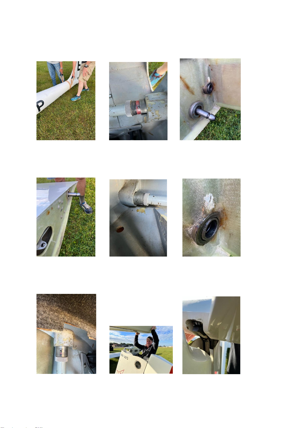
1.9 While wings are still in the trailer, wipe the main wing fittings clean. Also clean the wing
fittings on the fuselage. Lubricate all spigots and sockets at the wing root and on the
fuselage with a thin coating of grease. Use grease sparingly Figures 3 & 4).
2. Wing Rigging:
2.1 Find four able-bodied individuals to install the wings. Two people will be needed to lift
and manoeuvre each individual wing root and two will be needed to lift and manoeuvre
the wingtip. Whilst manipulating the wing it is imperative to communicate all actions. The
right wing is installed first.
2.2 Slide the right wing from the trailer, roll it level. Manoeuvre the wing into the fuselage.
Gently move the wing vertically as well as fore and aft. Use the wing root/fuselage gap
as a reference to determine fore/aft wingtip movement and line the spigots up with the
sockets. It may also be necessary to lift or lower the front and/or back of the wing at the
root end to line up the spigots/sockets. KEEP FINGERS AWAY FROM THE GAP IF
YOU WANT TO KEEP THEM!
2.3 Get an observer to stand on the left side of the fuselage and get someone to raise or
lower the wing tip until the end of the spar is more or less vertically central in the
fuselage hole as viewed from the left.
2.4 Rotate the right wing, rear locking sleeve until the slot aligns with the pin and the sleave
springs inboard to encapsulate the pin (Figure 5). Leave the front locking sleave undone
to enable some positioning movement on the right wing should it be required when
aligning with the left wing. Support the right wing with a trestle.
2.5 Slide out the left wing from the trailer, roll it level. Manoeuvre the wing into the fuselage
moving it vertically as well as fore and aft in order to line up the spigots and sockets,
including the spigot on the end of the right wing spar. The spigots at the end of each
spar are the difficult ones. These mate with rose joints in the opposite wing (Figure 6).
Rose joints are spherical and able to swivel. If the spigot is even slightly misaligned,
they will do this and then the spigot will not enter. At this point it may be necessary to
have one or two helpers manoeuvre the right wing tip to help line up spigots and rose
joints/sockets from both sides. Have one person watching the two spigots as the second
wing is mounted, one on the first wing tip, and make sure that both spigots are aligned
both horizontally and vertically (by adjusting the position of both wing tips) before
pushing the second wing home. It helps to have both wings resting on trestles so that
the correct position can be maintained. Success is achieved with a satisfying clunk as
the left wing slides into position. At this point congratulate yourselves, the hard part
is done!
2.6 Rotate the remaining three locking sleaves until the slots align with the pins and the
sleave springs inboard to encapsulate the pins (Figure 7). Secure and tighten all four
wing-fuselage locknuts by rotating them clockwise on their threads. Get one person on
each wing tip to pull the tips back so that you can further tighten the rear locknuts. Then
get these persons to pull the tips forward so you can further tighten the front locknuts.
Both wings are now securely in place.

3 Wing Control Connectors:
3.1 Whilst knelt in the rear fuselage facing rearwards, reach into the fuselage below the
baggage deck and connect the two aileron connectors (rear) and two airbrake
connectors (front). This is accomplished by pressing the slider on the top of each arm
and sliding it back so that the pin underneath can be lifted up into the respective ring
bearing on the wing side of the control arm. Once released the slider should move
forward to prevent the pin from disengaging with the bearing.
3.2 Get a qualified person to independently check the four wing and four control
connections before closing the baggage deck access panel and refitting the side and
front pads on the rear seat.
4 Fitting the Horizontal Stabiliser/Elevator:
4.1 Use three individuals to install the horizontal stabiliser.
4.2 Remove the horizontal stabiliser from its location in the trailer ceiling. Ensure that the
locking bolt at the front of the horizontal stabiliser is pulled completely forward.
4.3 Position the horizontal stabiliser above the fin and lower with the elevator angled
upwards. Lower the whole assembly with one person watching and guiding the elevator
housing onto the roller bearing at the top of the fin (Figures 8 & 9).
4.4 Gently lower and push back the stabiliser until it engages with the spigots in the fin. It is
in the correct position when the red line on the left side of the fin aligns with the red line
on the underside of the stabiliser (Figure 10).
4.5 Engage and wind in the locking bolt using its wingnut until it is fully in and just finger
tight (Figure 11). The wing nut should be horizontal thus allow the fibreglass cover to be
hinged up over it.
4.6 Place one finger vertically on the end of the stabiliser and gently rock it up and down to
ensure there is no movement.
4.7 Get a qualified person to independently check that the elevator connection housing is
properly located on the roller bearing. The tailplane is now securely in place.
5 Completion Activities:
5.1 Tape up the wing roots and tailplane/fin joints.
5.2 Fit the pitot tube (top) and total energy tube (bottom) on the front of the fin. Use wing
tape to secure the joint on the pitot, the total energy tube has a rubber seal.
5.3 Get a qualified person to help you do positive control checks then note the logbook that
a rig and positive check has been conducted.
5.4 Lower the belly dolly and slide the glider backwards to clear it.
5.5 Put the belly dolly in the trailer and secure.
CONGRATULATIONS, RIGGING COMPLETE

Points to Note on De-Rigging:
1. Remove tape from wing roots and tailplane/fin.
2. Remove pitot tube and total energy tube and place in front cockpit (closing the trailer lid
with them still on the fin will damage them and the surrounding gel).
3. Manoeuvre glider onto the belly dolly such that the rear of the dolly aligns with the rear of
the red pattern on the side of the fuselage. Use the tool (located in the trailer tailgate) to
raise the belly dolly to the high position so that the fuselage no longer rests on the
mainwheel.
4. Remove the tailplane and stow it in the ceiling of the trailer.
5. Remove the central pad and undo the side pads on the rear seat. Open the baggage
area floor panel.
6. Disconnect all four controls (2 x ailerons and 2 x airbrakes). Unscrew the nuts on all 4
wing mounts, slide the sleaves outwards so that the clear the pins then rotate them so
that the pins can’t drop back into the sleave grooves. If you don’t do this the wings will
remain attached regardless of pulling.
7. Remove the wings in any order. Note when sliding the starboard wing into the trailer it
may be necessary to get a couple of helpers to lift the root end slightly to clear the felt
leading edge holder half-way down the trailer. Put the aileron locks on both wings.
8. Slide the fuselage into the trailer, lifting the tail with the double-handled strap to ensure it
goes in without scraping the underside of the fuselage on the trailer floor. Roll the
fuselage forward until the tail wheel drops into its retaining hole then secure with the
strap.
9. Remember that the trailer is an Anschau, not a Cobra, so the roof must be lowered
before the tailgate is lifted. This is because the tailgate engages in the two spigots on the
back of the roof.

Helpful Photos:
Figure 1 Figure 2 Figure 3
Figure 4 Figure 5 Figure 6
Figure 7 Figure 8 Figure 9

Figure 10 Figure 11
Table of contents
Other Grob Aircraft manuals