DIMENSIONS AND AREAS, MAJOR COMPONENT LOCATIONS
2A-06-10: General
The Gulfstream V is powered by two BMW / Rolls Royce BR710 high bypass ratio
turbofan engines mounted on pylons located on the aft upper fuselage. The aircraft is
supported by a fully retractable tricycle landing gear.
The fuselage is of semimonocoque metal construction.All areas are pressurized with the
exception of the nose radome and aft equipment (tail) compartment. The fuselage is
divided lengthwise into an above-floor section and a below-floor section.
The wing contains the integral fuel tanks in its primary structure. Forward of the fuel
tanks, on the leading edge, wing anti-icing ducts and landing lights are installed. Aft of
the fuel tanks, on the trailing edge, primary and secondary flight controls are installed.
The primary flight controls are the ailerons, with the left aileron having an adjustable trim
tab. Secondary flight controls include the flaps (one per side) and spoilers (three per
side). Winglets are installed at the outboard end of each wing to aid in drag reduction and
improve fuel economy. Also contained within the wing is the main landing gear
supporting structure.
The tail section of the aircraft consists of a fixed vertical stabilizer and an adjustable
horizontal stabilizer. Primary flight controls contained within the tail section are left and
right elevators attached to the trailing edge of the horizontal stabilizer, and a rudder
attached to the trailing edge of the vertical stabilizer. The elevators have adjustable trim
tabs incorporated, whereas rudder trim is accomplished by displacement of the entire
surface.
The Dimensions, Areas and Major Component Locations section is divided into the
following subsections:
•2A-06-20: Principal Dimensions
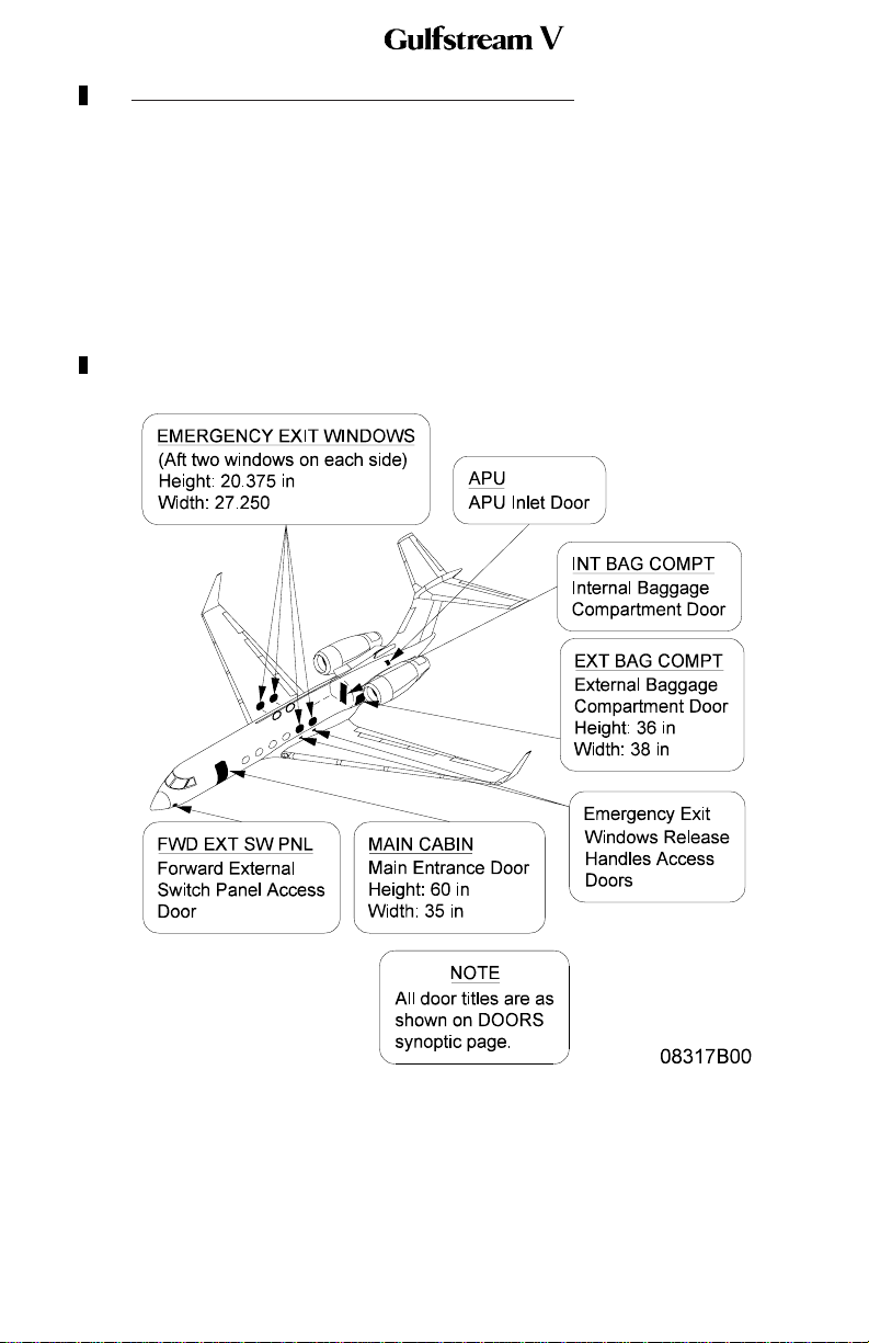
•2A-06-30: Entrances, Exits and External Access Doors
•2A-06-40: Flight Crew Station Components
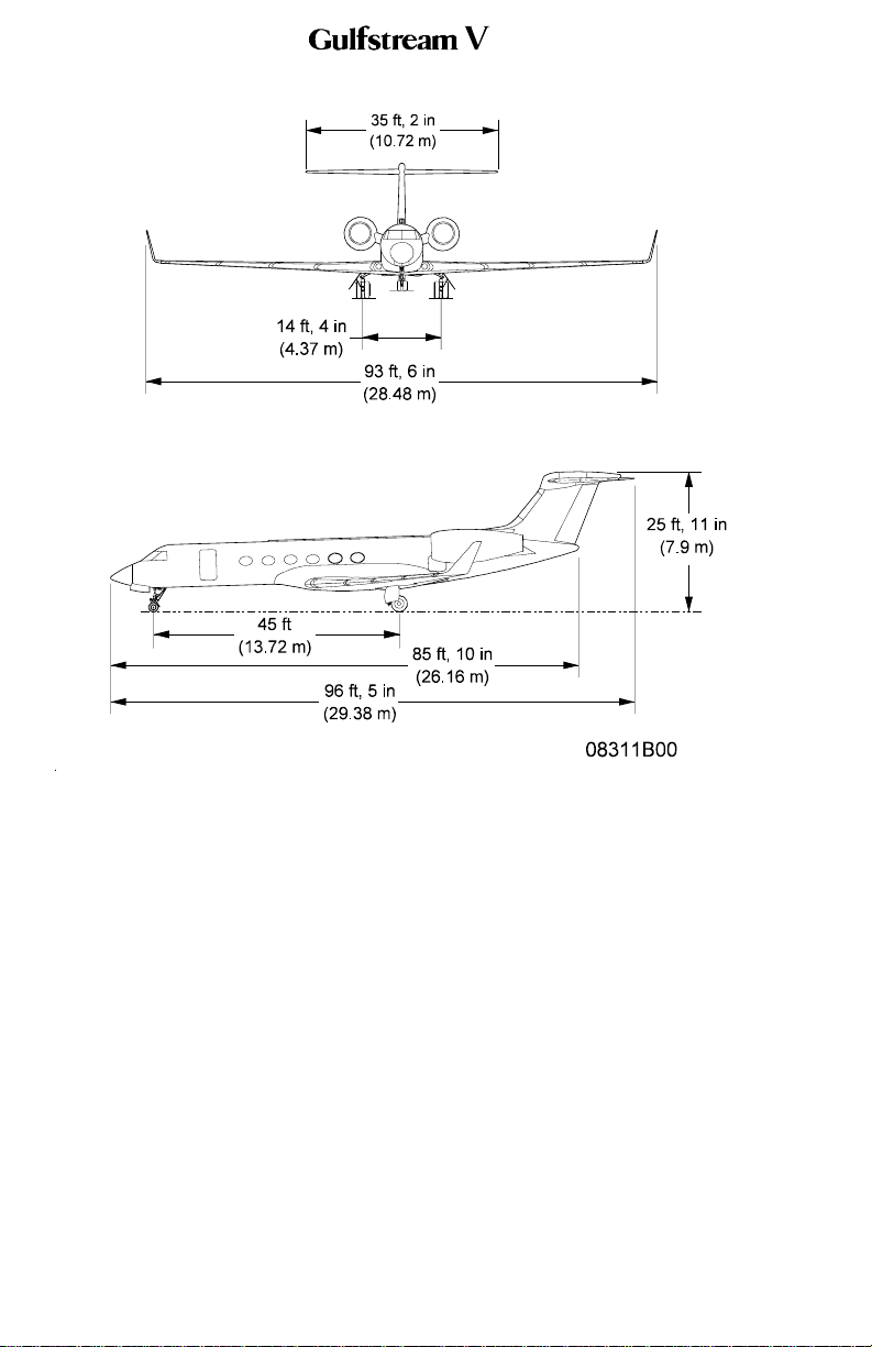
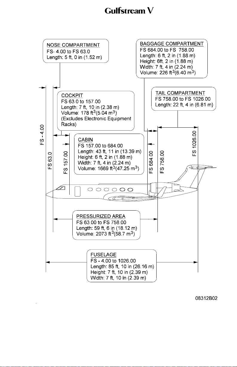
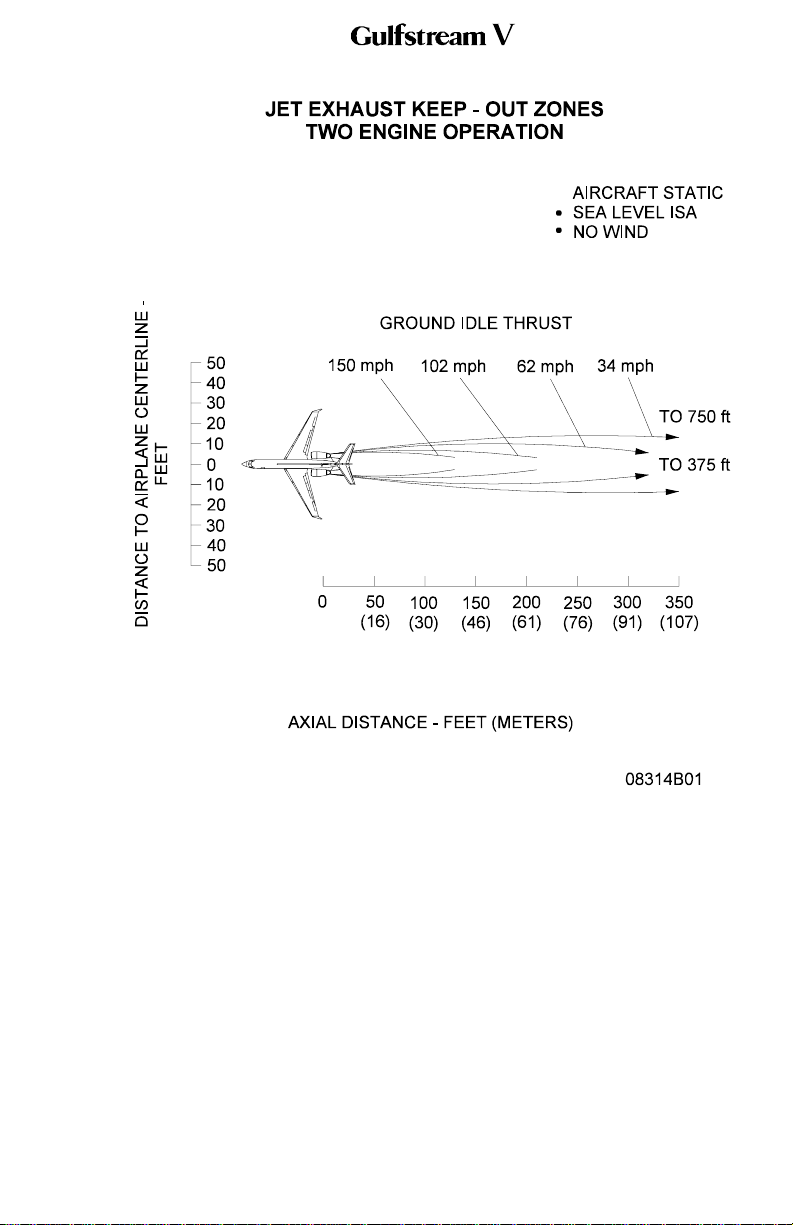
2A-06-20: Principal Dimensions
1. Dimensions, Areas and Distances:
See Figure 1 through Figure 4 for principal dimensions, areas and distances.
OPERATING MANUAL
PRODUCTION AIRCRAFT SYSTEMS 2A-06-00
Page 1
May 20/02