Grob Astir CS G102 Technical specifications

FLIGHT MANUAL G102
The Manual belongs to ASTIR CS
Registration Number: Serial Number:
Manufactured by: Burkhart Grob Flugzeugbau
86874 Tussenhausen - Mattsies
Flugplatz Mindelheim - Mattsies
Telephone: 08268-998-0
Germany
Owner:
Published: August 1975
This manual should always be kept on board the glider

FLIGHT MANUAL ASTIR CS
Rev. 9 28. Nov. 2005
2
List of effective pages
Chapter Page Date Reference
Flight Manual
Cover Page
2
3
4
5
6
7
8
9
10
11
12
13
14
15
16
17
18
19
20
21
22
23
28.11.2005
28.11.2005
28.11.2005
28.11.2005
28.11.2005
28.11.2005
28.11.2005
28.11.2005
28.11.2005
28.11.2005
28.11.2005
28.11.2005
28.11.2005
28.11.2005
28.11.2005
28.11.2005
28.11.2005
28.11.2005
28.11.2005
28.11.2005
28.11.2005
28.11.2005
28.11.2005

FLIGHT MANUAL ASTIR CS
Rev. 9 28. Nov. 2005
3
Contents
Contents page
List of effective pages........................................................................... 2
Contents................................................................................................ 3
Addenda................................................................................................ 4
Flying Limitations.................................................................................. 5
Record of weight alterations and weighing........................................... 7
Placards to be displayed in the cockpit ................................................ 9
Notes on Flying the Glider.................................................................. 13
Emergency Procedures...................................................................... 16
Minimum equipment ........................................................................... 18
Weight and center of gravity positions ............................................... 18
Measurements.................................................................................... 18
Weights and moments of the control surfaces ................................... 22
Assembly ............................................................................................ 22
Checks to be made after assembly .................................................... 24
Pre-Launch checks............................................................................. 24


FLIGHT MANUAL ASTIR CS
Rev. 9 28. Nov. 2005
5
Flying Limitations
Airspeed Limits (I.A.S.) km/h mph kts
Never exceed (V
NE
) ..............................250 ...........155..........135
in rough air (V
B
)................................... 250 .......... 155......... 135
Maneuvering (V
A
) ...............................170 .......... 105 ...........92
On aero tow (VT) .................................... 170............105 ............92
On winch tow (Vw) ...................................120 ............. 74.............64
Airbrakes ................................................. 250............ 155...........135
Gear extended ....................................... 250 ........... 155 ..........135
A.S.I. Colour Code
33 - 92 kts .............................. Green Border - 60-170 km/h
92 - 135 kts ............................ Yellow Border - 170-250 km/h
At 135 kts ..........................................Red Strip - bei 250 km/h
Weights lbs kp
Empty Weight.................................................circa 560..........255
Maximum permitted weight
without water-ballast ...........................................836 ........ 380
with water-ballast ............................................... 990 .........450
Maximum permitted weight
of non-supporting ports
...........................................
528
..........
240
Weak Link on Winch cable
Maximum Load
.......................................................
1100
..........
500
Cloud Flying and simple Aerobatics
Permitted if water-ballast is not being carried: See pages 12 - 14

FLIGHT MANUAL ASTIR CS
Rev. 9 28. Nov. 2005
6
Classification Group
Standard Class (German N)
Centre of Gravity positions
Leveling means with a 1000:40 Incidence Board
set up horizontal on the top of
the rear fuselage.
Datum Line (D, L.) Front edge) of wing at root
Serial-No. 1002 – 1437:
Maximum forward position of C. of G. 250 mm behind D. L. (9.84 in)
Maximum rearward position 425 mm behind D. L. (16.73 in)
Serial–No. 1438 – 1536:
Maximum forward position of C. of G. 310 mm behind D. L. (12,20 in)
Maximum rearward position 480 mm behind D. L. (18,90 in)
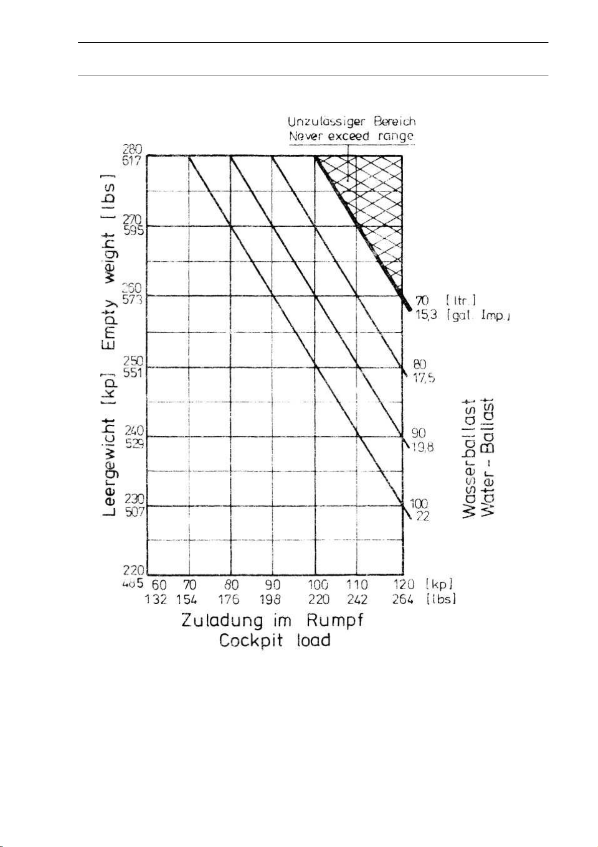
Loading Limitations ASTIR CS
Empty weight of glider and maximum cockpit load, see page 7.
Minimum cockpit load: 154 lbs (70 kp)
The permissible all up weight must NEVER be exceeded.
Maximum all up weight
without water-ballast 836 lbs (380 kp)
with water-ballast 990 lbs (450 kp)
The weight of water-ballast is dependent on the cockpit weight (Pilot
with parachute and luggage). See page 7.
Weight deficiencies should be corrected by securing or removing some
ballast in the seat.
The C. of G. of the pilot with a parachute on lies 475 mm in front of
the Datum Line.

FLIGHT MANUAL ASTIR CS
Rev. 9 28. Nov. 2005
7
Record of weight alterations and weighing
ASTIR CS Works Number:
Date of weight
alteration:
Weighing by
List of
accessories
(Date):
Empty Weight
(lbs):
Empty Weight
C. of G.
position
behind D.L.
(mm)
Maximum
Cockpit
Weight (lbs)

FLIGHT MANUAL ASTIR CS
Rev. 9 28. Nov. 2005
8

FLIGHT MANUAL ASTIR CS
Rev. 9 28. Nov. 2005
9
Placards to be displayed in the cockpit
Placard to be displayed near undercarriage
Maximum weight kp lbs
without water ballast: 380 836
with water ballast: 450 990
Airspeed limits km/h rn.p.h. knots
Never exceed 250 155 135
in rou
g
h air 250 155 135
Manoeuvrin
g
170 105 92
On aero tow 170 105 92
On winch tow 120 74 64
A
irbrakes 250 155 135
Gear extended 250 155 135
Weak links for towing
500 kp, 1100 lbs. max.
Tire: 2,5 bar, 36
p
si
Payload (pilot and parachute)
The maximum weight must not be exceeded.
Minimum payload: 70 kp, 154 lbs.
Less weight must be compensated with
ballast in the seat.

FLIGHT MANUAL ASTIR CS
Rev. 9 28. Nov. 2005
10
Ballast Weight
Pilot Weight
Incl. Parachute
Quantity
(Total)
kg lbs
55 120 6
60 130 4
65 145 2
70 - 100 155 - 220 0
Cover of the container has to be closed tight.
Ballast weight
red

FLIGHT MANUAL ASTIR CS
Rev. 9 28. Nov. 2005
11
Pedal
Adjustment
Small BLACK
knob
On the top of the
Instrument panel
(right hand)
Air-vent
Small BLACK
knob
On the top of the
instrument panel.
(left hand)
Cable Release
In front of the stick
on the left.
YELLOW knob
DOWN Under-carriage UP
Handle moves in
Slot on right of
cockpit
Trimmer
On left of cockpit.
GREEN lever
Air-brakes
On the left-hand
Side of the cockpit
BLUE handle
Water-ballast
Jettison
On the right of the
Cockpit.
WHITE lever
Canopy
Round RED knobs.
Left of canopy-frame
OPEN.
Right of canopy-
Frame JETTISON

FLIGHT MANUAL ASTIR CS
Rev. 9 28. Nov. 2005
12
Graph of True v. Indicated Airspeed, showing the effect of Position
Errors.
When the A.S.I. is connected to the following pressure sources:
A.S.I. - Pitot head in tail fin static vents side of the fuselage before the wing root.

FLIGHT MANUAL ASTIR CS
Rev. 9 28. Nov. 2005
13
Notes on Flying the Glider
Winch/Auto-tow-Launch
Maximum permitted launch speed: 64 kts
The glider has a belly-hook in the undercarriage well in front of the wheel. A cable
launch presents no difficulties with any C. of G. positions or weight configurations. The
glider has no tendency to balloon and is very stable on the launch. Up to a height of
300ft the nose should be held down if the launch is fast.
Aero tow
Maximum permitted towing speed: 92 kts
The gliders C. of G. position allows the aero tow to be carried out using either the nose
— or belly-hook. During the whole of the time on tow, the glider can be easily controlled
with rudder and aileron, full movements of which can be used if necessary. Even in
strong cross-winds the glider shows no tendency to wander around. At 32 kts the glider
can be lifted off: with 37 — 40 kts indicated, the glider climbs on its own. The
undercarriage can be retracted whilst still on tow. The yellow release knob is positioned
on the left in front of the stick, and should be pulled fully back when releasing the tow-
rope.
Weak Link in tow-cable
Maximum load 1100 lbs
Rudder-pedal Adjustment
To adjust the rudder pedals, push lightly forward on them with the heels and disconnect
the locking device by pulling the handle on the instrument panel. The pedals move
towards the pilot by themselves: to adjust them forward you have to push them against
the pressure of the springs with your heels. The pedals will lock themselves in the
position required when the handle is released.
Canopy
The single-piece perspex canopy has a clear-vision panel and ventilation port, and is
fitted on hinges. The handle for opening it is located on the left-hand side of the canopy
surround: that for jettisoning is on the right-hand fuselage side. To jettison the canopy,
pull both handles back and push it up and away with the left hand.

FLIGHT MANUAL ASTIR CS
Rev. 9 28. Nov. 2005
14
Retractable Undercarriage
The undercarriage control lever is located on the right of the cockpit. When retracted or
lowered, the wheel should be locked in place by pushing the control lever in towards
the fuselage side.
Air-brakes
The lever for the air-brakes is situated on the left-hand side of the cockpit. Before
beginning a launch, check that the air-brakes are closed and locked. One should avoid
trying to land with full brake out, since the effectiveness of the brakes means that the
glider is descending fast.
Wheel brake
The lever for the wheel brake is located on the stick.
Trim
The built-in trimmer can be progressively adjusted. The control lever for it is positioned
on the left-hand side of the cockpit behind the airbrake lever. Trim range from 32 kts —
97 kts.
Flight with water-ballast
The glider has the same all up weight as a standard 2 seat glider, when loaded with
water-ballast and a full cockpit load. The slow flight and stalling characteristics of the
fully loaded glider are a little different from one flown without water-ballast. The stalling
speed will be increased to 38 kts. Also larger control movements will be necessary.
The glider will spin cleanly but will recover immediately spin recovery action is taken.
The pilot is advised to have extra height when slow flying or approaching to land while
carrying water-ballast.
Use of Water-ballast
The water-ballast tanks are situated in the front part of the wings, from the root
outwards. Each wing can hold 50 litres. The tanks are filled through an opening in the
top surface of the wing. This is covered by a plug, which can be removed by screwing in
a bolt. The water is drained off through an opening in the underside of the fuselage
behind the wheel-box. To open the valves of the tanks, the control lever on the right-
hand side of the cockpit should be pulled backwards. It takes about 3 minutes for the
tanks to empty themselves.

FLIGHT MANUAL ASTIR CS
Rev. 9 28. Nov. 2005
15
Air from the tanks escapes through the overflow pipe that runs down to a point an the
underside of the wing near the root. When flying with water-ballast the connecting-tape
that covers the gap between fuselage and wings, should be folded back on the
underside in the region of the spar, so that any excess water which may appear runs out
rather than down into the fuselage.
During long flights at an air temperature of 0 ° C (32 ° F) the water-ballast must be
jettisoned because there is danger of collapse of the ballast tanks. When a field landing is
to be made the water-ballast must be jettisoned.
The glider must not be parked over-night with water-ballast on board. If the glider has to
be towed for a long way on the ground with water-ballast on board, the tanks should be
emptied.
When de-rigging the water-ballast tanks will empty themselves through the wing root
connecting pipes.
Stalling Characteristics
Warning of the stall occurs at a speed of 32-35 kts (depending on wing loading), when the
top of the tail unit begins to shudder. If the stick is pulled back even further, the glider
"mushes" but, remains controllable, it being possible to make turns up to an angle of
bank of 20' without the wing dropping away. If the stick is released the glider returns
immediately to the normal flying attitude. If the stick is pulled back quickly, the nose will
drop away but any tendency for a wing to fall can be controlled by the rudder.
Aerobatics
Permitted maneuvers and speeds at which they should be initiated:
Loop ..........................................................................................................................92 kts
Chandelle...................................................................................................................92 kts
Steep turn................................................................................................................. 65 kts
Lazy eight ..................................................................................................................65 kts
Spins:
From the fully stalled position, put on full aileron and rudder (crossed). Keep the stick
back. To stop the spin centralize or release one of the controls. Height lost per rotation
is approximately 220 ft. The speed reached when leveling out is about 86 kts.
Maximal positive g loading + 5,3.
Manoeuvres that involve negative g loads are prohibited.
Unorthodox manoeuvres are likewise prohibited

FLIGHT MANUAL ASTIR CS
Rev. 9 28. Nov. 2005
16
Spinning
With the Center of Gravity between 415 mm and 480 mm behind the Datum Line, it is
possible to put the glider into a spin from the stalled position. To do so the stick has to
be pulled fully back, and the rudder and aileron controls be fully crossed. The nose will
then drop in the direction in which rudder is being applied, and with a rearward C of G.
position the glider will rotate in a slow, flat spin.
Recovery from the spin can be effected in any way you choose. With almost all C. of G.
positions and wing loadings all that is required is for one of the controls to be released
or returned to its normal position. The quickest recovery (without overstressing the
glider) can be brought about by centralizing all of the controls. The height lost in
returning to the normal flying position after a single-rotation spin, is about 220 ft,
If the glider fails to stop spinning immediately the controls have been centralized, then
the standard method of spin recovery should be employed at once:
1. Full opposite rudder
2. Pause
3. Stick steadily forward
4. When spin stops, centralize controls and resume normal flight
Speed Flying
In speed flying it is quite possible to exceed the maximum permitted speed. At very high
air speeds, care should be taken to use only small control movements so as not to
overstress the glider:
Emergency Procedures
Escape Procedure
In the event of a bail out, the following procedure should be followed:
1. Pull both red knobs back on right and left of canopy surround and with left hand
push canopy upwards and backwards.
2. Unbuckle seat harness.
3. EXIT over left or right side
4. Wait only 1 — 3 seconds before pulling the rip cord

FLIGHT MANUAL ASTIR CS
Rev. 9 28. Nov. 2005
17
Flying at High Speed
Within the permitted speed range the glider has no tendency towards high speed flutter.
The controls need only be used at 1/3 of their full movement at 93 kts. The air brakes are
speed limiting and with them open the glider will only reach about 108 kts even in a 45°
dive.
Approach and Landing
The glider can be brought in quite normally at an approach speed of 50 kts. The air-
brakes allow a steep approach to be made quite easily. As the action of the brakes makes
the glider slightly nose-heavy, the machine will itself maintain the airspeed it is set at
when the brakes are opened. The sideslip is quite controllable and, if needed, this
manoeuvre can be used to help land the glider.
ATTENTION:
Landing circuit check: Height 500 ft.
Airspeed 50 kts.
WHEEL DOWN AND LOCKED
Flying in rain
A thin layer of water or ice on the wings leads to no deterioration in the flying
characteristics of the glider. With more substantial deposits the stalling speed is
increased by about 3 kts, although the way the glider takes off and touches down
remains the same. Increase the normal flying speed accordingly.
Cloud-flying
The minimum set of Instruments required before cloud flying should be attempted is:
A.S.I., Altimeter, Compass, Turn and Slip Indicator and Radio
The A.S.I. must have the maximum permitted speed marked on it, i. e. red section.
In order to avoid exceeding the maximum permitted speed, the airbrakes should be
opened in good time (i. e. at about 86 kts.)
Warning: Cloud flying and aerobatics should only be carried out by pilots who possess
the appropriate authorization. The statutory regulations must be adhered to.

FLIGHT MANUAL ASTIR CS
Rev. 9 28. Nov. 2005
18
Minimum equipment
1. 160kts. A.S.I
2. Altimeter
3.
Vertical speed indicator
4. Four piece safety harness
5. Weighted seat cushion at least 2 3/4", thick, or parachute
6. Loading limitations chart
7. Flying limitations placard
8. Flight manual
Weight and center of gravity positions
If new Instruments are added and other changes in the weight of the glider are
made, the empty weight C. of G. position should be checked. If the limits of the
empty weight C. of G. positions and the Loading Limitations Chart are adhered to,
then the C. of G. of the loaded glider will lie within the permitted range.
Serial-No. 1001- 1437 Serial-No. 1438 - 1536
Empty C. of G. position Empty C. of G. position
Weight (lbs) (mm behind Weight (lbs) (mm behind
Datum Line) Datum Line)
506
606 — 693 539 696 — 753
517
598 — 693 550 688 — 747
528
591 — 637 561 681 — 742
539
534 — 682 572 673
—
737
550 577 — 677 583 652
—
732
561 557 — 672 594 631
—
728
572 537 — 667 605 611
—
723
583 518 — 662 616 591
—
719
594 499 — 658 527 573
—
715
605 481 — 654
Measurements
Position of the glider whilst taking all measurements:
with a 1000:40 Incidence Board set up horizontal on the top of the rear fuselage.

FLIGHT MANUAL ASTIR CS
Rev. 9 28. Nov. 2005
19
ASTIR CS Serial No. 1438 – 1536

FLIGHT MANUAL ASTIR CS
Rev. 9 28. Nov. 2005
20
Performance 350 kp 450 kp
Best Glide Angle 37,3 - 95 38 – 105km/h
Minimum Sink (m/sec) 0,6 -75 0,7 – 85 km/h
Circling speed 80 – 85 90 – 95 km/h
Table of contents
Other Grob Aircraft manuals