AC3OperaonandMaintenance
Operaon
6
Recommended Lubricants
TheACPumphasbeendevelopedspecificallytorunwithNLGIGrade000,00,0,1and2greaseandFG3,0fluid
grease.OilstoaminimumviscosityofSAE80arealsoacceptable.Donotuseheavytackifiedgreasesorgreases
containingbentone/bentonite,molybdenumand/orgraphite.
NOTE: Toensureproperoperaonofthelubricaonsystemonlyeverfillwithcleanlubricantthathasbeenina
sealedcontainerandcorrectlystored.Ifcleanlubricantisnotuseditcanresultinprematuresystemorbearing
failures.
Typical Refill Periods
TheAC3refillperiodsrangegreatly,dependingonthenumberofpumpingunits,theoutputquanes,andthe
programmeddelaymes.Duetotheaccuracyofthepumpingunitsoutputquanesandthereliabilityofpump
funconalityrefillperiodscanbesimplycalculatedtoensurethatthepumpandthebearingpointsdon’trundry.
Usethefollowingtocalculaterefillperiods:
Key:
N=NumberofPumpingUnits(P.U.)witha
parcularoutputvolume.
O1=0.010ccOutput(RedP.U.)
O2=0.015ccOutput(GreenP.U.)
O3=0.025ccOutput(YellowP.U.)
O4=0.040ccOutput(BlueP.U.)
O5=0.060ccOutput(GreyP.U.)
O6=0.100ccOutput(BlackP.U.)
A=TotalOutputAmountper1revoluon
E=NumberofrevoluonsunlEmpty
R1=2,800ccAC3Reservoir
M=1.13=Motorrunmeof1min8secs.
P=Programmeddelayme(3,7,11,15,19,
24,30or36minutes).
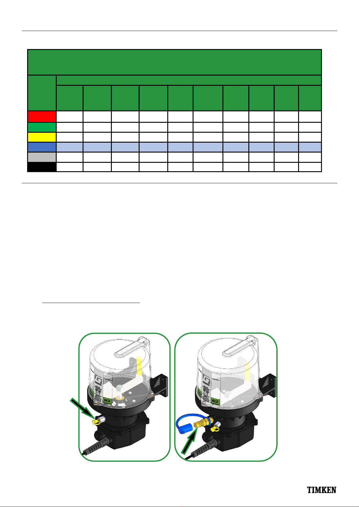
AC3
Pumps
Recommended Lubricants
OilsSAE80/90 000Fluid 00SemiFluid 0So 1Sff 2Hard
Minimum
operaon
Temp.
‐40°C/‐40°F ‐35°C/‐31°F ‐30°C/‐22°F ‐25°C/‐13°F ‐20°C/‐4°F ‐15°C/5°F
Maximum
operaon
Temp.
+50°C/122°Fforallpumps*
*(Motorisoperableupto60°C/140°F,butoperangatover50°C/122°Fshortensthelifeofthepump).
Calculaon:
Addupthetotaloutputfromallpumpingunits:
(NxO1)+(NxO2)+(NxO3)+(NxO4)+(NxO5)+(NxO6)=A
Dividethereservoircapacity(R1orR2)bythetotaloutput(A):
R1orR2=E
A
Mulplythenumberofrevsunlempty(E)bythepro‐
grammeddelayme(P),plustherunme(M):
Ex(P+M)=TotalRunmeinminutes(T)
T/60=TotalRunmeinhours(H)
H/24=TotalRunmeindays
Example:
AnAC3(R1)calibratedwith2RedP.U.(O1),4YellowP.U.(O3)
&6GreyP.U.(O5)programmedfora15minutedelayme:
(2x0.01)+(4x0.025)+(6x0.06)=0.48cc
2800cc/0.48cc=5833.33Revs
5833.33x(15+1.13)=87500minutesunlempty,
19531.25/60=1458.33hoursunlempty,
1458.33/24=60.76daysbetweenrefills.
*Notethatthiscalculaonisbasedonthepumphavingan
uninterruptedpowersupplyandbeinginconnuousoperaon*