manuals.online logo
Brands
  1. Home
  2. •
  3. Brands
  4. •
  5. Grohe
  6. •
  7. Plumbing Product
  8. •
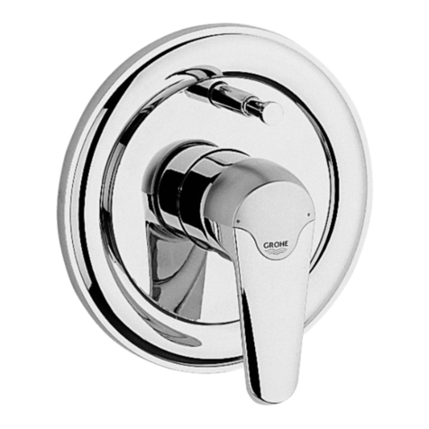
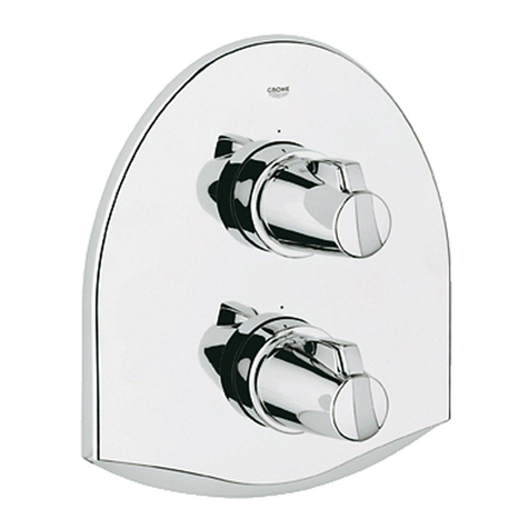
  9. Grohe Taron 19 658 User manual

Grohe Taron 19 658 User manual

................ 18
...........12
Sida.......7
DSeite.....1 NL
PL
GB S
UAE
FDK
GR
E
N
CZ
I
FIN
H
Page.....2
Page.....3
Página..4
Pagina...5
Pagina...6
Side.......8
Side......9
Sivu ....10
Strona. 11
Σελιδα.13
Strana.14
Oldal ...15
PPágina.16
Sayfa.......17
TR
RUS
SK Strana......19
19 658
95.548.131/ÄM 30 134/10.99
Taron
...........18
...........12
Sida.......7
DSeite.....1 NL
PL
GB S
UAE
FDK
GR
E
N
CZ
I
FIN
H
Page.....2
Page.....3
Página..4
Pagina...5
Pagina...6
Side.......8
Side......9
Sivu ....10
Strona. 11
Σελιδα.13
Strana.14
Oldal ...15
PPágina.16
Sayfa..17
TR
RUS
SK Strana.19
955481.book : T95548.FM Seite 1 Montag, Oktober 11, 1999 10:01 AM
I
A
B
1
G
H
I
3
C
DAQ1 R1
2
Please pass these instructions on to the end user of the fitting.
S.v.p remettre cette instruction à l'utilisateur de la robinetterie!
Bitte diese Anleitung an den Benutzer der Armatur weitergeben!
JK
L
M
J
4
KL955481.FM Seite 2 Montag, Oktober 11, 1999 9:56 AM
II
KL955481.FM Seite 3 Montag, Oktober 11, 1999 9:56 AM
2
GB
Installation to finished stage
- Plaster and tile the wall, excluding the area occupied by the
mounting template. Seal any apertures in the wall so that they
are watertight to spray water.
•Tiles laid in mortar should be pointed so that the joint is
tapered towards the outside.
•Seal prefabricated walls with a permanently plastic compound.
- Remove the mounting template, see fig. [1].
- Unscrew adjusting nut (A). Detach stop ring (B), see fig. [1] and
fold-out page II.
- Install sleeve (C), remove stop ring (B) and fit stop ring (D)
provided with marking facing upwards, see figs. [1] and [2].
- Install adjusting nut (A) and fit snap insert (Q1) with screw and
spring (R1), see fig. [2].
- Install holder (G), screw-mount sleeve (H) and secure with screw
ring (I), see fig. [3].
- Grease the seals (J) for the escutcheon mounting bracket (K)
with the special grease supplied and install escutcheonmounting
bracket (K) with lever mounting assembly (L), see fig. [4].
- Fit the escutcheon (M), see fig. [4].
If the thermostat has been installed at too great a depth, this
can be adjusted by 27.5mm with an extension set (see fold-out
page II, ref. No. 47 358).
Reversed union (hot on right - cold on left).
Replace thermoelement (A1), see replacement parts
fold-out page II, ref. No.: 47 282 (1/2”).
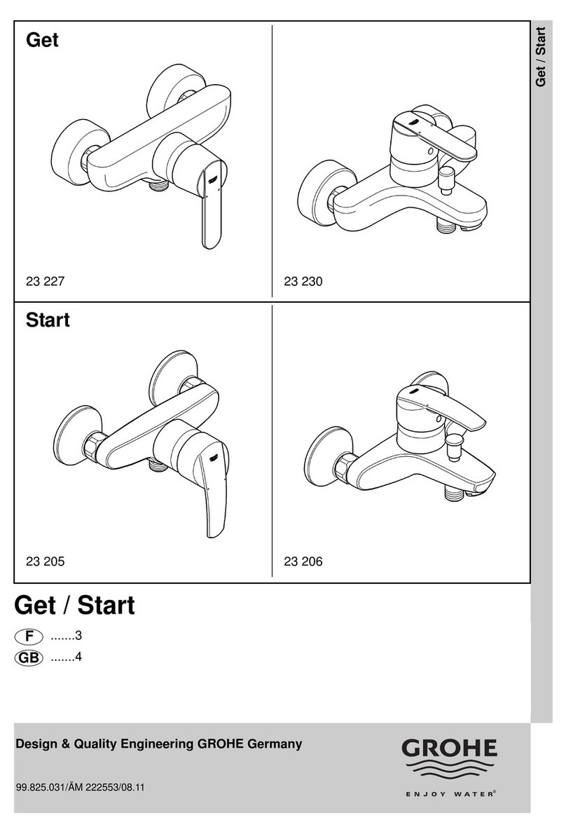
Installation of the flow control knob and adjustment of the
economy stop, see figs. [5] to [7].
•The flow rate is limited by the economy stop (N) supplied,
see fig. [5].
To install the flow control knob, proceed as follows:
1. Close the ceramic headpart by turning clockwise.
2. Install the economy stop (N) in the desired position, see fig. [5].
For possible settings, see fig. [6].
- Fit sleeve (O) so that the mark PULL is at top, see fig. [7].
- Fit splined adapter (P) with snap insert (Q2) and screw with
spring (R2), see fig. [7].
- Install flow control knob (S) in such a way that the mark
coincides with the mark PULL on the sleeve (O), see fig. [7].
If a higher rate is desired, the stop can be overridden by pulling the
flow control knob (S).
Adjustment
Installation of the thermostat knob and temperature
adjustment, see figs. [8] and [9].
•Before the mixer is put into service if the mixed water
temperature measured at the point of discharge varies from the
specified temperature set on the thermostat.
•After any maintenance operation on the thermoelement.
1. Open the shutt-off valve and check the temperature of the water
with a thermometer, see fig. [8].
2. Turn the adjusting nut (A) clockwise or anticlockwise until the
water temperature reaches 38 °C, see fig. [8].
3. Fit scale ring (T) so that the mark PULL is at top, see fig. [9].
4. Install temperature control handle (U) in such a way that the
mark coincides with the mark PULL on the scale ring (T),
see fig. [9].
Temperature limitation
The safety stop limits the temperature range to 38 °C.
If a higher temperature is desired, the 38 °C limit can be overridden
by pulling the temperature control handle.
Prevention of frost damage
When the domestic water system is drained, thermostat mixers
must be drained separately, since non-return valves are installed in
the hot and cold water connections.
The complete thermostat assemblies and non-return valves must
be unscrewed and removed.
Maintenance
For maintenance, see fold-out page II and fig. [10].
Shut off hot and cold water supplies.
I.Thermoelement
1. Pull off temperature control handle (U) and scale ring (T).
2. Remove adjusting nut (A).
3. Pull off stop ring (D).
4. With a 24mm open-ended spanner, unscrew and remove
thermoelement (A1).
II. Non-return valve
1. Pull off temperature control handle (U) and flow control knob (S).
2. Detach escutcheon (M) in accordance with fig. [10].
3. Remove screws (V) and escutcheon mounting bracket (K).
4. Unscrew and remove non-return valve (E1) with 17mm socket
wrench.
III. Ceramic headpart
1. Proceed as for maintenance of non-return valve, points 1-3.
2. Remove screw (X), pull off spring (Z) and snap insert (Q2).
3. Remove splined adapter (P), sleeve (O) and economy stop (N).
4. Remove screw ring (I), pull off sleeve (H) and remove holder (G).
5. With a 17mm open-ended spanner, unscrew and remove
ceramic headpart (G1).
Inspect and clean all parts, replace if necessary and grease with
special valve grease (ref. No. 18 012).
Reassemble in the reverse order.
Observe the correct mounting position!
Use only genuine Grohe replacement parts.
Replacement parts, see fold-out page II (* = special accessories).
Readjustment is necessary after every maintenance operation on
the thermoelement (see Adjustment).
Care
For directions on the care of this thermostat mixer, please refer to
the accompanying Care Instructions.
I955481.book : I95548GB.FM Seite 2 Freitag, Juli 16, 1999 2:09 PM
III
OP
R2 S
Q2
7
6
A
8
5
N
TU
9
M
10
955481.book : KR95548.FM Seite 23 Montag, Oktober 11, 1999 10:01 AM

This manual suits for next models

1

Other Grohe Plumbing Product manuals

Grohe 29 025 User manual

Grohe

Grohe 29 025 User manual

Grohe Ashford 32 459 User manual

Grohe

Grohe Ashford 32 459 User manual

Grohe Allure F-digital 36 342 User manual

Grohe

Grohe Allure F-digital 36 342 User manual

Grohe Pulsomat User manual

Grohe

Grohe Pulsomat User manual

Grohe Allure F-digital 36 345 User manual

Grohe

Grohe Allure F-digital 36 345 User manual

Grohe Europlus E + Powerbox 36 387 User manual

Grohe

Grohe Europlus E + Powerbox 36 387 User manual

Grohe Allure 34 236 User manual

Grohe

Grohe Allure 34 236 User manual

Grohe Movario 28 390 Movario 28 391 User manual

Grohe

Grohe Movario 28 390 Movario 28 391 User manual

Grohe Grohmix 19 231 User manual

Grohe

Grohe Grohmix 19 231 User manual

Grohe 34 507 User manual

Grohe

Grohe 34 507 User manual

Grohe Eurosmart Cosmopolitan 20 199 User manual

Grohe

Grohe Eurosmart Cosmopolitan 20 199 User manual

Grohe SENSIA IGS User manual

Grohe

Grohe SENSIA IGS User manual

Grohe ATRIO 29216001 User manual

Grohe

Grohe ATRIO 29216001 User manual

Grohe Grohtherm 3000 User manual

Grohe

Grohe Grohtherm 3000 User manual

Grohe Blue Pure 30 499 User manual

Grohe

Grohe Blue Pure 30 499 User manual

Grohe Touch Cosmopolitan 23 220 User manual

Grohe

Grohe Touch Cosmopolitan 23 220 User manual

Grohe Ondus 20 149 User manual

Grohe

Grohe Ondus 20 149 User manual

Grohe GRANDERA 20 418 User manual

Grohe

Grohe GRANDERA 20 418 User manual

Grohe Atrio 21 046 User manual

Grohe

Grohe Atrio 21 046 User manual

Grohe Tectron 37 321 User manual

Grohe

Grohe Tectron 37 321 User manual

Grohe Veris 13 245 User manual

Grohe

Grohe Veris 13 245 User manual

Grohe Grohtherm 1000 User manual

Grohe

Grohe Grohtherm 1000 User manual

Grohe GROHTHERM XL 35 085 User manual

Grohe

Grohe GROHTHERM XL 35 085 User manual

Grohe 26 475 User manual

Grohe

Grohe 26 475 User manual

Popular Plumbing Product manuals by other brands

Insignia KY003 Series installation manual

Insignia

Insignia KY003 Series installation manual

vonRoll hydro LEAKPEN operating instructions

vonRoll hydro

vonRoll hydro LEAKPEN operating instructions

FCI ASF-0001 installation manual

FCI

FCI ASF-0001 installation manual

Spectrum Brands Pfister Capistrano LF-048-CSO Quick installation guide

Spectrum Brands

Spectrum Brands Pfister Capistrano LF-048-CSO Quick installation guide

agape ARUB1036 Installation and maintenance instructions

agape

agape ARUB1036 Installation and maintenance instructions

AmazonBasics B07F2C8L8T Guide

AmazonBasics

AmazonBasics B07F2C8L8T Guide

Hans Grohe Vernis Blend 71456 Series Instructions for use/assembly instructions

Hans Grohe

Hans Grohe Vernis Blend 71456 Series Instructions for use/assembly instructions

FM Mattsson FMM 4282 Instruction

FM Mattsson

FM Mattsson FMM 4282 Instruction

Kohler K-7514 owner's manual

Kohler

Kohler K-7514 owner's manual

BARBERI 29B N Series quick start guide

BARBERI

BARBERI 29B N Series quick start guide

Sanela SLZM 20VIN Mounting instructions

Sanela

Sanela SLZM 20VIN Mounting instructions

American Standard Colony Right Height Elongated 12" Rough-In Toilet... Specification sheet

American Standard

American Standard Colony Right Height Elongated 12" Rough-In Toilet... Specification sheet

Santec TH-8010 Installation instruction

Santec

Santec TH-8010 Installation instruction

HOLL'S Alto Vap Installation handbook

HOLL'S

HOLL'S Alto Vap Installation handbook

Hewi 801.51.100 Mounting instructions

Hewi

Hewi 801.51.100 Mounting instructions

Helvex Clasica 100 installation guide

Helvex

Helvex Clasica 100 installation guide

Mofem MLU-54N24 quick start guide

Mofem

Mofem MLU-54N24 quick start guide

American Standard Corner Minette 0451.001 Specification sheet

American Standard

American Standard Corner Minette 0451.001 Specification sheet

manuals.online logo
manuals.online logoBrands
  • About & Mission
  • Contact us
  • Privacy Policy
  • Terms and Conditions

Copyright 2025 Manuals.Online. All Rights Reserved.