manuals.online logo
Brands
  1. Home
  2. •
  3. Brands
  4. •
  5. Grundig
  6. •
  7. CD Player
  8. •
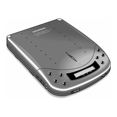
  9. Grundig CD 103 User manual

Grundig CD 103 User manual

Service
Manual
Bei
Eingriffen
SchutzmaBnahmen
fir
MOS-Bauteile
beachten!
Das
Gerat
muB
auch nach
der
Reparatur
den
Sicherheitsbestimmun-
gen
nach
DIN/AEC
65
VDE
0860
enitsprechen.
Inhaltsverzeichnis
Laser
-
Sicherheit
Behandlung
von
MOS
-
Bauteilen
Sicherheitsvorschriften
Ausbauhinweise
:
Mechanische
Einstellungen
Explosionszeichnung
CD
-
Laufwerk
Explosionszeichnung
CD
103
Ersatzteilliste
t
Abgleich
Abgleichlagepian
Legende
ot
IC-Innenschaltbilder
und
Beschreibufng
Druckplatten
‘
Schaitbild
Blockschaltbild
Anderungen
vorbehalten
Subject
to
alteration
_
Printed
in
Germany
0191
H
CD
Bix
_*
32700
#
CD
103
SACH-NR.
/
PART
NO.:
75987
-
556.00
G.LA
22
N.B.
When
carrying
out
repairs,
observe
MOS
precautions!
After
the
unit
has
been
repaired,
it
should
still
meetthe
DIN/IEC
65
VDE
0860
safety
requirements.
Contents
Laser
safety
Handling
of
MOS
Chip
Components
Safety
requirements
Disassembly
Instructions
Mechanicl
adjustments
Exploded
view
of
CD
mechanism
Exploded
view
of
CD
103
Spare
parts
List
Alignment
Alignment
Layout
Legende
IC
Block
Diagram
and
Description
Printed
Circuit
Boards
Wiring
Diagram
Block
Diagram
Page
2
2-3
4-6
Service
Manual
CD
103
Sachnummer/Order
No.:72010-718.70
LASER
-
Sicherheit
Da
viele
Bauteile,
besonders
die
Laserdiode,
gegen
statische
Aufla-
dungen
empfindlich
sind,
mlissen
die
MOS
-
Vorschriften
eingehalten
werden.
Die
Abtasteinheit
besteht
aus
vielen
Prazisionsteilen
und
sollte
vor
hohen.
Temperaturen,
hoher
Luftfeuchtigkeit,
starken
Magnetfeldern,
starken
Erschiitterungen
und
Staub
geschitzt
werden.
LASER
Safety
‘The
MOS
safety
requirements
must
be
met
because
many.
compo-
nents,
particularly
the
laser
diode,
are
very
sensitive
to
static
electri-
city.
The
pick-up
unit
incorporates
many
precisioon
components
and
should
therefore
be
protected
against
high
temperatures,
high
humi-
dity,
strong
magnetic
fields,
shocks
and
dust.
CLASS
1
LASER
PRODUCT
-
CD-
Spieler
gehéren
zur
Gerategruppe
mit
LASERN
geringer
Leistung.
-
Nach
DIN
VDE
0837
bzw.
IEC
825
handelt
es
sich
um
einen
LASER
der
Klasse
1.
Das
besagt,
die
Ausgangsleistung
ist
kon-
struktiv
begrenzt.
Ein
Betrieb
der
LASER-DIODE
auBerhalb
der
Abtasteinheit
ist
beim
Betrachten
des
LASER-Lichtes
fiir
das
Auge
schadlich,
da.
die
Ausgangsleistung
um
ein
Vielfaches
héher
liegt
(
Klasse
3
B
).
In
diesen
Fall
ist
das
Tragen
einer
Laserschutzbrille
zwingend
vorgeschrieben.
-
Durch
das
Linsensystem
der
Abtasteinheit
liegt
der
Brennpunkt
des
LASER-Lichtes
etwa
1,5mm
Uber
der
Fokuslinse.
Da
der
Brennpunkt
sehr
tief
liegt,
kann
der
LASER
mit
dem
bloBen
Auge
betrachtet
werden.
~
Das
Betrachten
des
LASERS
mit
externen
Optiken,
z.B.
Lupe,
ist
zu
vermeiden,
da
diese
den
Brennpunkt
auf
die
Netzhaut
des
Auges
projezieren
und
so
das
Auge
geschadigt
werden
kann.
-
Das
LASER-Licht
kann
an
der
Fokuslinse
des
Abtasters
als
ein
dunkelroter
Punkt
beobachtet
werden,
wenn
man
schrag
auf
die
Optik
sieht.
Die
Umgebungshelligkeit
soll
dabei
nicht
zu
groB
sein.
-
Durch
das
Auflegen
eines
Transparentpapiers
auf
die
Fokuslinse
ist
der
LASER-Punkt
als
Projektion
auf
die
Papierrtickseite
gut
erkennbar.
-
Augenschutz
bei
Servicearbeiten
ist
nicht
notwendig.
Sicherheitsverriegelungen
verhindern
im
Normalfall,
daB
der
LASER
bei
gedffnetem
Deckel
arbeitet.
Unter
Beachtung
0.g.
Hinweise
lassen
sich
die
schaltungsspezifischen
Si-
cherheitsverriegelungen
ausschalten,
und
der
LASER
wird
als
kleiner
roter
Punkt
sichtbar.
Klasse
1
Ungefahrlich
fiir
das
menschliche
Auge.
Maximale
Ausgangsleistung
z.B.
bei
700
nm
-
69
wW.
Klasse
3
B
Gefahrlich
fur
das
menschliche
Auge
und
in
besonderen
Fallen
flr
die
Haut.
Maximale
Strahlungsleistung
bis
0,5
W.
GP
VARO!
Avattaessa
ja
suojalukitus
ohitettaessa
olet
alttiina
nakymattémalle
la-
sersateilylle.
Ala
katso
sateeseen.
CD
Behandlung
von
MOS
-
Bauelementen
Schaltungen
in
MOS-Technik
bedtirfen
besonderer
Vorsichtsma8-
nahmen
gegeniber
statischer
Aufladung.
Statische
Aufladungen
k6énnen
an
allen
hochisolierenden
Kunststoffen
auftreten
und
auf
den
Menschen
Ubertragen
werden,
wenn
Kleidung
und
Schuhe
aus
synthetischem
Material
bestehen.
Schutzstrukturen
an
den
Ein-
und
Ausgangen
der
MOS-Schaltungen
geben
wegen
ihrer
Ansprechzeit
nur
begrenzte
Sicherheit.
Bitte
beachten
Sie
folgende
Regeln,
um
Bauelemente
vor
Beschadi-
gung
durch
statische
Aufladungen
zu
schitzen:
1.
MOS-Schaltungen
sollen
bis
zur
Verarbeitung
in
elektrisch
leiten-
den
Verpackungen
verbleiben.
Keinesfalls
MOS-Bauteile
in
Styro-
por
oder
Plastikschienen
lagern
oder
transportieren.
2.
Personen
miissen
sich
durch
Beriihren
eines
geerdeten
Gegen-
standes
entladen,
bevor
sie
MOS-Bauteile
anfassen.
-
The
CD
Player
belongs
to
the
category
of
products
with
lowpower
LASER.
-
According
to
DIN
VDE
0837
or
IEC
825
itis
a
Class
1
LASER
mea-
ning
that
the
output
power
limits
are
determined
by
the
design.
The
LASER
DIODE
must
not
be
operated
outside
the
pick-up
sin-
ce
the
output
power
increases
many
times
over
(
Class
3B
)
and
causes
injuries
of
the
eye.
In
this
case
the
use
of
a
LASER
protective
goggles
is
highly
prescribed.
-
Due
tothe
lens
system
of
the
LASER
pick-up
the
focal
point
of
the
LASER
light
is
about
1,5mm
above
the
focus
lens.
The
focal
point
is
located
deep
enough
to
allow
the
LASER
to
be
looked
at
with
unprotected
eyes.
-
Avoid
looking
at
the
LASER
using
external
optical
means
such
as,
for
example,
a
magnifying
glass
because
the
focal
point
will
be
projected
onto
the
retina
and
may
cause
injuries
of
the
eye.
-
The
LASER
light
appears
on
the
focus
lens
of
the
pick-up
as
a
darkred
spot
when
looking
at
the
optical
system
at
an
angle,
preferrably
at
low
ambient
brightness.
-
By
putting
a
transparent
paper
onto
the
focus
lens
the
LASER
spotis
projected
onto
the
back
of
the
sheet
and
is
well
perceivable.
-
Itis
not
necessary
to
protect
the
eyes
during
repair
works.
In
general,
built-in
safety
locks
ensure
that
the
LASER
does
not
operate
with
open
disc
compartment
cover.
In
conside-
ration
of
the
above
instructions,
the
special
safety
locks
can
be
made
ineffective
and
the
LASER
will
be
visible
as
a
small
red
spot.
Class
1
Not
dangerous
for
the
human
eye.
Maximum
output
power
eg:
at
700
nm
-
69
pW.
Class
3B
Dangerous
for
the
human
eye
and,
in
special
cases,
for
the
skin.
Maximum
radiation
power
up
to
0,5
W.
cS
VARNING!
Osynlig
laserstralning
nar
denna
del
ar
6ppnad
och
sparren
ar
urkop-
plad.
Betrakta
ej
stralen.
3.
MOS-Bauelemente
nur
am
Gehause
anfassen,
ohne
die
Anschltis-
se
zu
berthren.
4.
Prifung
und
Bearbeitung
nur
an
geerdeten
Geraten
vornehmen.
5.L6sen
oder
kontaktieren
Sie
MOS-ICs
in
Steckfassungen
nicht
unter
Betriebsspannung.
6.
Bei
p-Kanal-MOS-Bauelementen
diirfen
keine
positiven
Span-
nungen
(bezogen
auf
den
SubstratanschluB
VSS)
an
die
Schaltung
gelangen.
Létvorschriften
fir
MOS-Schaltungen:
¢
Nur
netzgetrennte
Niedervoltl6tkolben
verwenden.
+
Maximale
Léizeit
5
Sekunden
bei
einer
L6tkolbentemperatur
von
300
°C
bis
400
°C.
Handling
of
MOS
Chip
Components
MOS
circuits
require
special
attention
with
regard
to
static
charges.
Static
charges
may
occur
with
any
highly
insulating
plastics
and
can
be
transferred
to
persons
wearing
clothes
and
shoes
made
of
synthe-
tic
materials.
Protective
circuits
on
the
inputs
and
outputs
of
MOS
circuits
give
protection
to
a
limited
extent
only
due
to
the
time
of
reaction.
Please
observe
the
following
instructions
to
protect
the
components
against
damages
from
static
charges:
1.
Keep
MOS
components
in
conductive
packages
until
they
are
used.
MOS
components
must
never
be
stored
or
transported
in
Styropor
materials
or
plastic
magazines.
2.
Persons
have
to
rid
themselves
of
electrostatic
charges
by
touching
a
grounded
object
before
handling
MOS
components.
3.
Take
the
chip
by
the
body
without
touching
the
terminals.
4.
Use
only
grounded
instruments
for
testing
and
processing
purposes.
5.
Remove
or
connect
MOS
ICs
with
in
mounting
sockets
only
if
the
operating
voltage
is
disconnected.
6.
The
circuits
of
p-channel
MOS
components
must
not
be
connected
to
positive
voltages
(with
reference
to
bulk
VSS).
MOS
Soldering
Instructions
.
Use
only
mains
isolated
low-voltage
soldering
irons.
*
Maximum
soldering
period
5
seconds
at
a
soldering
iron
temperature
of
300
to
400
degrees
Celsius.
CE
Précautions
a
prendre
pour
la
manipulation
des
circuits
MOS
Les
circuits
équipés
en
technique
MOS
exigent
des
précautions
particuliéres
contre
les
charges
statiques.
Des
charges
statiques
peuvent
se
créer
sur
toutes
les
matiéres
synthétiques
a
fort
pouvoir
isolant,
elles
peuvent
se
transmettre
au
corps
humain
et
le
risque
est
d’autant
plus
important
si
la
personne
porte
des
vétements
ou
des
chaussures
en
matiére
synthétique.
Les
systémes
de
protection
dont
sont
équipées
les
entrées
et
sorties
des
circuits
MOS
n‘apportent
qu’une
sécurité
limitée
du
fait
de
leur
temps
de
fonctionnement.
Afin
de
protéger
les
composants
contre
les
charges
statiques,
il
est
recommandé
d’observer
les
régles
suivantes:
1.
Les
circuits
MOS
doivent
rester
placés
dans
un
matérial
conduc-
teur
jusqu’au
moment
de
leur
utilisation.
Il
ne
doivent
en
aucun
cas
étre
stockés
ou
transportés
dans
du
styropore
ou
sur
des
bandes
de
plastique.
2.
Les
personnes
travaillant
sur
des
circuits
MOS
doivent
au
préalable
se
décharger
de
leur
charge
statique
en
touchant
un
object
mis
a
terre.
3.
Les
ensembles
équipés
de
circuits
MOS
doivent
étre
saisis
unique-
ment
par
leur
boitier,
on
ne
doit
pas
toucher
les
broches
de
raccordement.
4.
On
ne
doit
effectuer
de
contréles
et
travaux
que
sur
des
appareils
mis
a
la
terre.
5.
Ne
jamais
retirer
ou
raccorder
un
circuit
MOS
sur
un
appareil
sous
tension.
6.
Les
circuits
MOS
canal
p
ne
doivent
en
aucun
cas
recevoir
de
ten-
sions
positives
(en
VSS
par
rapport
a
la
liaison
vers
le
substrat).
Prescription
de
soudure
sur
les
circuits
MOS
*
Nutiliser
que
des
fers
4
souder
basse
tension
isolés
du
secteur
*
Temps
de
soudure
maximum
:
5
secondes
pour
une
température
comprise
entre
300
°C
et
400
°C.
<>
Impiego
dei
componenti
MOS
|
circuiti
in
tecnica
MOS
necessitano
di
una
particolare
attenzione
per
evitare
le
scariche
elettrostatiche.
Tutti
i
materiali
sintetici
ad
alto
potere
isolante
possono
caricar
si
staticamente
e
queste
cariche
possono
trasmettersi
all’uomo,
par
ticolarmente
se
scarpe
o
vestiti
sono
sintetici.
Le
strutture
di
sicurezza
sull’ingresso
e
sull’uscita
dei
circuiti
MOS
hanno
un’efficacia
limitata
a
causa
del
loro
periodo
di
intervento.
Per
proteggere
i
componenti
MOS
dalle
scariche
elettrostatiche
si
consigla
di
adottare
le
seguenti
precauzioni:
1.Fino
al
momento
del
loro
impiego,
i
MOS
devono
restare
in
materiale
elettricamente
conduttivo.
Non
trasportarli
o
depositarli
mai
in
listelli
di
plastica
o
in
polistirolo.
2.Le
persone
che
maneggiano
i
componenti
MOS
devona
prima
scaricar
si
elettrostaticamente
toccando
un
oggetto
con
collega-
menio
a
massa.
3.
Maneggiare
i
componenti
MOS
toccandone
solo
I’involucro
e
mai
i
piedini.
4.
Controlli
e
lavorazioni
devono
avvenire
soltanto
su
apparecchi
con
messa
a
terra.
5.Non
inserire
e
non
staccare
mai
gli
integrati
MOS
dagli
zoccoli
quando
la
tensione
di
alimentazione
é
collegata.
6.
Ai
componenti
MOS
canale
P
non
devono
giungere
tensioni
posi-
tive
(rif.
a
collegamento
del
substrato
VSS).
Norme
di
taratura
per
gli
integrati
MOS:
+
Impiegare
solo
saldatori
a
bassa
tensione
con
separazione
dalla
rete.
+
Il
tempo
massimo
di
saldatura
é
di
5
sec.
con
una
temperatura
del
saldatore
compresa
fra
300
°C
e
400
°C.
CED
Tratamiento
de
componentes
en
técnica
MOS
Los
circuitos
contruidos
en
técnica
MOS
precisan
un
cuidado
espe-
cial
contra
las
cargas
estaticas.
En
todos
los
materiales
plasticos
de
elevado
aislamiento
pueden
aparecer
cargas
estaticas
y
también
ser
transmitidas
a
la
personas,
especialmente
cuando
las
ropas
y
zapatos
son
de
materia
sintética.
Las
estructuras
de
proteccién
en
las
entradas
y
salidas
de
los
integrados
MOS,
debido
a
su
tiempo
de
conexi6n,
proporcionan
sdlo
una
limitada
seguridad.
Para
proteger
los
médulos
de
las
descargas
estaticas
es
aconsejable
prestar
atencién
a
las
siguientes
reglas:
1.
Los
circuitos
integrados
MOS
deben
permanecer
envueltos
en
un
material
conductor
hasts
el
momento
de
su
empleo.
En
ningun
caso
se
jes
colocara
ni
transportara
en
recepientes
de
styropor
o
guias
de
plastico.
2.
Las
personas
que
trabajan
con
elementos
MOS
deben
descargar-
se
previamente
tocando
un
objecto
puesto
a
tierra.
3.
Los
elementos
MOS
solo
deben
cogerse
por
la
capsula,
sin
rozar
siquiera
los
terminales.
4.
Pruebas
y
trabajos
con
los
circuitos
MOS
slo
deben
realizarse
en
aparatos
que
estén
puestos
a
tierra.
5.No
extraer
ni
establecer
contacto
bajo
tensién
de
funcionamiento
de
los
IC’s
MOS
enchufables.
6.En
los
componentes
MOS
canal-p
no
deben
llegar
tensiones
positivas
(con
respecto
a
la
tensién
de
substrato
VSS)
a
los
circuitos.
Prescipciones
para
la
soldadura
de
los
circuitos
integrados
MOS:
«
Utilizar
Gnicamente
soldadores
de
baja
tensién
con
transformador-
separador
de
/a
red.
¢
Tiempo
maximo
de
soldadura:
5
segundos
con
una
temperatura
entre
300
y
400
°C.
Sicherheitsvorschriften
/
Safety
requirements
/
Prescriptions
de
sécurité
/
Prescrizioni
de
sicurezza/
Prescripciones
de
seguridad
Achtung:
Bei
Eingriffen
ins
Gerat
sind
die
Sicherheitsvor-
schriften
nach
VDE
701
(reparaturbezogen)
bzw.
VDE
0860
/
IEC
65
(geratebezogen)
zu
beachten!
\
iN
Bauteile
nach
IEC-
bzw.
VDE-Richtlinien!
Im
Ersatzfalt
nur
Teile
mit
gleicher
Spezifikation
verwenden!
MOS
-
Vorschriften
beim
Umgang
mit
MOS
-
Bauteilen
be-
achten!
Attention:
Please
observe
the
applicable
safety
require-
ments
according
to
VDE
701
(concerning
repairs)
and
VDE
0860
/
IEC
65
(concerning
type
of
product)!
)
Components
to
IEC
or
VDE
guidelines!
Only
use
compo-
Js
nents
with
the
same
specifications
for
replacement!
Observe
MOS
components
handling
instructions
when
ser-
vicing!
CF)
Attention:
Priere
d'observer
les
prescriptions
de
sécurité
VDE
701
(concernant
les
reparations)
et
VDE
0860
/
IEC
65
(concernant
le
type
de
produit)!
(\
,
Composants
répondant
aux
normes
VDE
ou
IEC.
Les
rem-
placer
uniquement
par
des
composants
ayant
les
mémes
spécifications.
Lors
de
la
manipulation
des
circuits
MOS,
respecter
les
pescriptions
MOS!
Attenzione:
Osservarne
le
corrispondenti
prescrizioni
di
sicurezza
VDE
701
(concernente
servizio)
e
VDE
0860
/
IEC
65
(concernente
il
tipo
di
prodotto)!
\
Componenii
secondo
le
norme
VDE
risp.
te
IEC!
In
caso
di
/
sostituzione
impiegare
solo
componenti
con
le
stesse
carat-
teristiche.
Osservare
le
relative
prescrizioni
durante,
lavori
con
com-
ponenti
MOS!
;
CED
Atencion:
Recomendamos
las
normas
de
seguridad
VDE
u
otras
normas
equivalentes,
por
ejemplo:
VDE
701
para
re-
paraciones,
VDE
0860
/
IEC
65
para
aparatos!
Componentes
que
cumplen
las
normas
VDE/IEC.
En
caso
vA
|
\
J
de
sustituci6n,
emplear
componentes
con
idénticas
especi-
ficaciones!
Durante
la
reparacion
observar
las
normas
sobre
com-
ponentes
MOS!
Attention:
This
set
can
only
be
operated
from
AC
mains
of
u.s.3
120
V/60
Hz.
Also
observe
the
information
given
on
the
rear
Canada
Of
the
set.
CAUTION-for
continued
protection
against
risk
of
fire
re-
/\
A
place
only
with
same
type
of
fuses!
CAUTION:
to
reduce
the
risk
of
electric
shock,
do
not
re-
move
cover
(or
back),
no
user-serviceable
parts
inside,
refer
servicing
to
qualified
service
personnel.
Components
to
safety
guidelines
(IEC/U.L.)!
Only
use
com-
/\
ponents
with
the
same
specifications
for
replacement!
Observe
by
checking
leakage-current
or
resistance
measu-
rement
that
the
exposed
parts
are
acceptably
insulated
from
the
supply
circuit.
Observe
MOS
components
handling
instructions
when
ser-
vicing!
@
Sicherheitsbestimmungen
Nach
Servicearbeiten
ist
bei
Geraten
der
Schutzklasse
II
die
Mes-
sung
des
Isolationswiderstandes
und
des
Ableitstromes
bei
einge-
schaltetem
Gerat
nach
VDE
0701
/
Teil
200
bzw.
der
am
Aufstellort
geltenden
Vorschrift
durchzuftihren!
Dieses
Gerat
entspricht
der
Schutzklasse
II,
erkennbar
durch
das
Symbol
[G)
.
e@
Messen
des
Isolationswiderstandes
nach
VDE
0701.
Isolationsmesser
(U
,.,,
=
500
V-)
gleichzeitig
an
beiden
Netzpo-
len
und
zwischen
allen
Gehause-
oder
Funktionsteilen
(Antenne,
Buchsen,
Tasten,
Zierteilen,
Schrauben,
usw.)
aus
Metall
oder
Metallegierungen
anlegen.
Fehlerfrei
ist
das
Gerat
bei
einem:
R
iso)
2
2
MQ
bei
U
+...
=
500
V-
MeBzeit:
=
1
s
(Fig.
1)
Anmerkung:
Bei
Geraten
der
Schutzklasse
Il
kann
durch
Enila-
dungswiderstande
der
MeBwert
des
Isolationswiderstandes
kon-
siruktionsbedingt
<
2
MQ
sein.
In
diesen
Fallen
ist
die
Ableitstrom-
messung
maBgebend.
Priifling
Test
item
Apparecchio
in
misura
Piéce
d’essai
Aparato
de
prueba
Netzstecker
des
Priiflings
Mains
plug
of
test
item
Spina
di
rete
dell“apparecchio
in
misura
Fiche
secteur
piéce
d’
essai
Ma
METRATESTER
3
Clavija
de
red
del
aparato
de
prueba
Prifling
Test
item
Apparecchio
in
misura
Piéce
d’essai
Aparato
de
prueba
Fig.
1
Netzstecker
des
Priiflings
Mains
plug
of
test
item
’
Spina
di
rete
dell’apparecchio
in
misura
Fiche
secteur
piéce
d'
essai
ae
METRATESTER
3
Clavija
de
red
del
aparato
de
prueba
Fig.
2
e
Messen
des
Ableitstromes
nach
VDE
0701.
Ableitstrommesser
(U
Test
=
220
V=)
gleichzeitig
an
beiden
Netz-
polen
und
zwischen
allen
Gehause-
oder
Funktionsteilen
(Anten-
ne,
Buchsen,
Tasten,
Zierteilen,
Schrauben,
usw.)
aus
Metall
oder
Metallegierungen
anlegen.
Fehlerfrei
ist
das
Gerat
bei
einem:
|
ableit
<1
mA
bei
U
Test
MeBzeit:
=
1
s
(Fig.
2)
e@
Wirempfehlen,
die
Messungen
mitdemMETRATESTER
3
durch-
zufiihren.
(MeBgerat
zur
Priifung
elektrischer
Gerate
nach
VDE
0701).
Metrawatt
GmbH
Geschaitsstelle
Bayern
Triebstr.
44
D
8000
Minchen
50
@
Ist
die
Sicherheit
des
Gerates
nicht
gegeben,
weil
-
eine
Instandsetzung
unmédglich
ist
-
oder
der
Wunsch
des
Beniitzers
besteht,
die
Instandsetzung
nicht
durchflhren
zu
lassen,
so
muB
dem
Betreiber
die
vom
Gerat
ausgehende
Gefahr
schriftlich
mitgeteilt
werden.
=
220
V=
__——-—«dMit
der
Greifklemme
alle
Metallteile
u.
metallisierten
Teile
abtasten.
All
metal
and
metallic
parts
must
be
tested
with
the
Caliper
clamp.
Con
cavo
prowvisto
di
morsetto
toccare
tutte
le
parti
metaliche
o
metallizzate.
A
\aide
d’une
pince
veérifier
toutes
les
parties
métalliques’
ou
métallisées.
Con
la
pinza,
tocar
todas
las
piezas
metdlicas
o
metalizadas.
Netzsiecker/Mains
plug/Spina
di
rete/Fiche
secteur/Clavija
de
red
Mit
der
Greifklemme
aile
Metallteile
u.
metallisierten
Teile
abtasten.
All
metal
and
metallic
parts
must
be
tested
with
the
Caliper
clamp.
Con
cavo
provvisto
di
morsetto
toccare
tutte
le
parti
metalliche
o
metallizzate.
“
A
Vaide
d’une
pince
vérifier
toutes
les
parties
métalliques
ou
métallisées.
Con
la
pinza,
tocar
todas
las
piezas
metalicas
o
metalizadas.
Netzstecker/Mains
plug/Spina
di
rete/Fiche
secteur/Clavija
de
red
Empfehlungen
fiir
den
Servicefall
@
Nur
Original
-
Ersatzteile
verwenden.
Bei
Bauteilen
oder
Baugruppen
mit
der
Sicherheitskennzeichnung
A\
sind
Original
-
Ersatzteile
zwingend
notwendig.
©
Auf
Sollwert
der
Sicherungen
achten.
e
Zur
Sicherheit
beitragende
Teile
des
Gerates
diirfen
weder
be-
schadigt
noch
offensichtlich
ungeeignet
sein.
®
Dies
gilt
besonders
flr
Isolierungen
und
Isolierteile.
@
Netzleitungen
und
AnschluBleitungen
sind
auf
4uBere
Mangel
vor
dem
AnschluB
zu
priifen.
Isolation
prifen!
@
Die
Funktionssicherheit
der
Zugentlastung
und
von
Biegeschutz-
tillen
ist
zu
priifen.
@
Thermisch
belastete
Létstellen
absaugen
und
neu
\éten.
e
Beltiftungen
frei
lassen.
Safety
Standard
Compliance
After
service
work
on
a
product
conforming
to
the
Safety
Class
II,
the
insulating
resistance
and
the
leakage
current
with
the
product
switch
on
must
be
checked
according
to
VDE
0701
or
to
the
specification
valid
at
the
installation
location!
This
product
conforms
to
the
Safety
Class
ll,
as
identified
by
the
symbol
;
e@
Measurement
of
the
Insulation
Resistance
to
VDE
0701,
Connect
an
Insulation
Meter
(U
,,,,
=
500
V-)
to
both
mains
poles
simultaneously
and
between
all
cabinet
or
functional
parts
(anten-
na,
sockets,
buttons,
decorative
parts,
etc.)
made
from
metal
or
metal
alloy.
The
product
is
fault
free
if:
R,..,2
2
MQ
at
U
=
500
V-
Isol
~
Test
Measuring
time:
2
1
s
(Fig.
1)
Comment:
On
products
conforming
to
the
Safety
class
Il
the
Insulation
Resistance
can
be
<
2
MOhm,
dependent
contructively
on
discharge
resistors.
In
this
case,
the
check
of
the
leakage
current
is
significant.
@
Measurement
of
the
Leakage
Current
to
VDE
0701.
Connect
the
Leakage
Current
Meter
(U_,,.,
=
220
V=)
to
both
mains
poles
simultaneously
and
between
all
cabinet
or
functional
parts
(antenna,
sockets,
buttons,
screws,
etc.)
made
from
metal
or
metal
alloy.
The
product
is
fault
free
if:
|
<1mA
at
U,,.,
=
220
V=
Leak
~~
Measuring
time:
2
1
s
(Fig.
2)
CE)
Prescriptions
de
sécurité
Suite
aux
travaux
de
maintenance
sur
les
appareils
de
la
classe
Il,
il
convient
de
mesurer
la
résistance
d’isolement
et
le
courant
defuite
sur
l'appareil
en
état
de
marche,
conformément
a
la
norme
VDE
0701
§
200,
ou
selon
les
prescriptions
en
vigueur
sur
le
lieu
de
fonctionne-
ment
de
l'appareil!
Cet
appareil
est
conforme
aux
prescriptions
de
sécurité
classe
Il,
signalé
par
le
symbole
[C1]
.
@
Mesure
de
la
résistance
d‘isolement
selon
VDE
0701
Brancher
un-appareil
de
mesure
diisolation
(U,,.,
=
500
V-)
simul-
tanément
sur
les
deux
pdles
secteur
et
entre
toutes
les
parties
métalliques
ou
métallisées
accessibles
de
l'appareil
(antenne,
em-
bases,
touches,
enjoliveurs,
vis,
etc.).
Le
fonctionnement
est
correct
lorsque:
R
iso:
=
2
M&
pour
une
U
soc,
=
500
V-
Durée
de
la
mesure:
2
1s
Observations:
L'isolation
des
appareils
de
la
classe
Il,
de
part
leur
conception
résistance
de
décharge),
peut
étre
intérieur
4
<
2
MQ,
(Fig.
1).
;
@
Mesure
du
courant
de
fuite
selon
VDE
0701
Brancher
un
ampéremétre
du
courant
de
fuite
(U
,,.,
=
220V=)
simultanément
sur
les
deux
péles
du
secteur
et
entre
toutes
les
parties
métalliques
ou
métallisée
accessibles
de
l'appareil
(anten-
ne,
embases,
touches,
enjoliveurs,
vis,
etc.).
Le
fonctionnement
est
correct
lorsque
(Fig.
2):
|
suite
IMA
pour
Uy
=
220
V=
Durée
de
la
mesure:
=>
1s
®
We
recommend
that
the
measurements
are
carried
out
using
the
METRATESTER
3.
(Test
equipment
for
checking
electrical
pro-
ducts
to
VDE
0701).
Metrawatt
GmbH
Geschaftsstelle
Bayern
Triebstr.
44
D
8000
Munchen
50
@
[If
the
safety
of
the
product
is
not
proved,
because
-
arepair
and
restoration
is
impossible
-
or
the
request
of
the
user
is
that
the
restoration
is
not
to
be
carried
out,
the
operator
of
the.
product
must
be
warned
of
the
danger
by
a
written
warning.
Recommendation
for
service
repairs
@
Use
only
original
spare
parts.
With
components
or
assemblies
accompanied
with
the
Safety
Symbol
A\
only
original
spare
parts
are
strictly
to
be
used.
@
Use
only
original
fuse
value.
@
Safety
compliance
parts
of
the
product
must
not
be
visually
dama-
ged
or
unsuitable.
This
is
valid
especially
for
insulators
and
insula-
ting
parts.
@
Mains
leads
and
connecting
leads
should
be
checked
for
external
damage
before
connection.
Check
the
insulation!
@
The
functional
safety
of
the
tension
relief
and
bending
protection
bushes
are
to
be
checked:
®
Thermally
loaded
solder
pads
are
to
be
sucked
off
and
re-soldered.
e
Ensure
that
the
ventilation
slots
are
not
obstructed.
@Pour
ces
mesures,
nous
préconisons
‘utilisation
du
METRATESTER
3
(instrument
de
mesure
pour
le
contrdle
d’appareils
électriques
conformes
ala
norme
VDE
07014).
Metrawatt
GmbH
Geschattsstelle
Bayern
Triebstr.
44
D
8000
Miinchen
50
@
Dans
le
cas
ot
la
sécurité
de
Pappareil
n’est
pas
assurée
pour
les
raisons
suivantes:
-
laremise
en
état
est
impossible
-
futilisateur
ne
souhatte
pas
la
remise
en
état
de
l'appareil.
l’utili-
sateur
doit
étre
informé
par
écrit
du
danger
que
représente
I'utili-
sation
de
l'appareil.
Recommandations
pour
la
maintenance
@
Utiliser
exclusivement
des
piéces
de
rechange
d'origine.
Les.com-
posants
et
ensembles
de
composants
signalés
par
le
symbole
Z\
doivent
étre
impérativement
remplacés
par
des
piéces
d'origine.
@
Respecter
la
valeur
nominale
des
fusibles.
@
Veiller
au
bon
état
et
la
conformité
des.piéces
contribuant
a
la
sécurité
de
fonctionnemenit
de
l'appareil.
Ceci
s’applique
particulié-
rement
aux
isolements
et
piéces
isolantes.
®
Vérifier
le
bon
état
extérieur
des
cables
secteur
et
des
cables
de
raccordement
au
point
de
vue
isolement
avant
la
mise
sous
tension.
@
Vérifier
le
bon
état
des
protections
de
gaine.
@
Nettoyer
les
soudures
avant
de
les
renouveler.
@
Dégager
les
voies
d’aération.
<p
Norme
di
sicurezza
Successivamente
ai
lavori
di
riparazione,
negli
apparecchi
della
classe
di
protezione
II
occorre
effettuare
la
misura
della
resistenza
di
isolamento
e
della
corrente
di
dispersione
quando
l’apparecchio
e’acceso,
secondo
le
norme
VDE
0701
/
parte
200
e
rispettivamente
le
norme
locali!
Questo
apparecchio
corrisponde
alla
classe
di
protezione
Il
ed
é
riconoscibile
dal
simbolo
ia
e
Misura
della
resistenza
di
isolamento
secondo
VDE
0701
Applicare
il
misuratore
di
isolamento
(tens.
proven
500
V-)
contem-
poraneamente
ai
due
poli
di
rete
e
tra
tutte
le
parti
del
mobile
e
delle
funzioni
(antenna,
prese,
tasti,
mascherine,
viti
ecc.)
in
metallo
o
in
lega
metallica.
L’apparecchio
non
presenta
difetti
quando:
R...,
=
2
MQ
con
tens.
=
500
V-
isol
~
prova
Tempo
di
misura:
=
1s
(Fig.
1)
Nota:
Negli
apparecchi
della
classe
Il,
che
per
motivi
costruttivi
dispongono
di
resistenze
di
dispersione,
il
valore
di
misura
della
resistenza
di
isolamento
pud
essere
inferiore
a
<
2
MQ.
In
questi
casi
é
determinante
la
misura
della
corrente
di
dispersione.
e@
Misura
della
corrente
di
dispersione
secondo
VDE
0701
Applicare
il
misuratore
di
isolamento
(tens.
eine
220
V=)
contem-
poraneamente
ai
due
poli
di
rete
e
tra
tutte
le
parti
del
mobile
e
delle
funzioni
(
antenna,
prese,
tasti,
mascherine,
viti
ecc.)
in
metallo
o
in
lega
matallica.
Lapparecchio
non
presenta
difetti
quando:
|
aise:
<1mAcontens.
nieve
=
220
V=
Tempo
di
misura:
2
1
s
(Fig.
2)
e@
Si
raccomanda
di
effettuare
le
misure
con
lo
strumento
METRATESTER
3
(strumento
di
misura
per
il
controllo
di
apparecchi
elettrici
secondo
VDE
0701).
Metrawatt
GmbH
Geschaftsstelle
Bayern
Triebstr.
44
D
8000
Miinchen
50
®
Se
ia
sicurezza
dell’apparecchio
non
é
raggiunta,
perché
-
una
riparazione
non
é
possibile
-
oppure
é
desiderio
del
cliente
che
una
riparaz.
non
avvenga
in
questi
casi
si
deve
comunicare
per
iscritto
all’utilizzat.
la
perico-
losita
dell’apparecchio
riguardo
il
suo
isolamento.
Raccomandazione
per
il
servizio
assistenza
@
Impiegare
solo
component
originali:
|
componenti
0
i
gruppi
di
componenii
contraddistinti
dall’
indicaz.
Z\
devono
assolutamente
venir
sostituiti
con
parti
originale.
e
Osservare
il
valore
nominale
dei
fusibili.
@
|
componenti
che
concorrono
alla
sicurezza
dell’apparecchio
non
possono
essere
né
danneggiati
né
risultare
visibilmente
inadatti.
Questo
vale
soprattutto
per
isolamenti
e
parti
isolate.
e@
|
cavi
di
rete
e
di
collegamento
vanno
controllati
prima
dell'utilizzo
affinché
non
presentino
imperfezioni
esteriori.
Controllare
l’isola-
mento.
®
E’necessario
controllare
la
sicurezza
dei
fermacavi
e
delle
guaine
flessibili.
@
Saldature
caricate
termicam.
vanno
rifatte.
e
Lasciare
libere
le
fessure
di
areazione.
©)
Disposiciones
para
la
Seguridad
Después
de
operaciones
de
servicio
en
aparatos
de
la
clase
de
proteccion
Il,
se
llevara
a
cabo
la
medida
de
la
resistencia
de
aislamiento
y
de
la
corriente
derivada,
con
el
aparato
conectado,
de
acuerdo
con
VDE
0701
0
de
las
disposiciones
vigentes
en
el
lugar
de
instalaci6n
.
Este
aparato
corresponde
ala
clase
de
proteccién
II,
reconocible
por
el
simbolo
:
@
Medida
de
la
resistencia
de
aislamiento
segun
VDE
0701.
Aplicar
el
medidor
de
aislamiento
(U
cniebar
500
V-),
simultanea-.
mente,
a
los
dos
polos
de
red
y
entre
todas
las
partes
del
mueble
o
de
funciones
(
antena,
conectores,
teclas,
tornillos,
etc.)
de
metal
0
aleaciones
metalicas.
El
aparato
estara
libre
de
defectos
con:
R
....2
2
MQ
con
U
=
500
V-
ais]
~
prueba
Tiempo
de
medida:
=
1
seg.
Observacion:
En
aparatos
de
la
clase
de
protecci6n
II,
condicionado
por
la
construccion
y
por
resistencias
de
descarga,
el
valor
de
medida
de
la
resistencia
de
aislamiento
puede
ser
inferior
a
<
2
MQ.
En
este
caso
es
decisiva
la
medida
de
la
corriente
derivada
(Fig.1).
@
Medida
de
la
corriente
derivada
de
acuerdo
con
VDE
0701.
Aplicar
el
medidor
de
corriente
derivada
(U
piieba=
220
V=)
simul-
taneamente
a
los
dos
polos
de
red’y
entre
todas
las
partes
del
mueble
o
de
funciones
(antena,
conectores,
teclas,
tornillos,
etc.)
de
metal
o
aleaciones
metdlicas.
El
aparato
estara
libre
de
defec-
tos
con
(Fig.2):
I
gery
<
1
MA
con
U
priepa
220
Vx.
Tiempo
de
medida:
=
1
seg.
@
Aconsejamos
llevar
a
cabo
las
medidas
con
el
METRATESTER
3
(Instrumento
de
medida
para
la
comprobacién
de
aparatos
eléctri-
cos
segun
VDE
0701).
Metrawatt
GmbH
Geschaftsstelle
Bayern
Triebstr.
44
D
8000
Munchen
50
@
Si
no
se
cumple
la
seguridad
del
aparato,
porpue
-
la
puesta
en
orden
es
imposible,
o
-
esiste
el
desco
del
usuario
de
no
realizarla,
se
ha
de
comunicar
a
quien
lo
haga
funcionar,
por
escrito,
del
peligro
dimanante
del
aparato.
Recomendaciones
para
caso
de
servicio
@
Emplear
sdlo
componentes
originales.
Con
componentes
o
grupos
constructivos
con
el
indicativo
de
se-
guridad
/\
son
de
obligada
necesidad
piezas
de
repuesto
origina-
les.
@
Las
partes
del
aparato
que
contribuyan
ala
seguridad
del
mismo
no
deben
estar
deterioradas
ni
ser
manifiestamente
inadecuadas.
@
Esto
es
especialmente
valido
para
aislamientos
o
piezas
aislantes.
@
Los
cables
de
red
y
de
conexin
se
comprobaran,
antes
de
conec-
tarlos,
en
cuanto
a
defectos
externos.
Comprobar
el
aislamiento.
@
Se
ha
de
comprobar
la
funcién
de
seguridad
de
la
compensacién
de
tiro
o
de
los
manguitos
de
proteccién
contra
doblamientos.
@
Repasar
los
puntos
de
soldadura
sometidos
a
carga
térmica.
@
Mantener
libres
los
canales
aireacin.
Ausbauhinweise
Gehauseoberteil
4
Schrauben
E
herausschrauben.
Gehauseoberteil
abnehmen.
CD
Laufwerk
Scheibe
12
abnehmen
und
Zahnrad
11
herausnehmen.
Disk-Klemmhebel
M1
anheben.
Schublade
17
nach
vorne
schieben.
Rastnase
ausrasten
und
Schublade
17
aus
dem
Gerat
ziehen.
2
Schrauben
13
herausschrauben,
Steckverbinder
l6sen
und
Lauf-
werk
entnehmen.
Vor
dem
Einbau
der
Schublade
das
Pick
up
M13
in
die
Stellung
bringen,
in
der
sich
die
Markierungen
der
Zahnrader
M20
und
M28
gegentiberstehen
(Pick
up
vorne).
Beim
Einbau
darauf
achten,
da
die
Markierung
des
Zahnrads
11
in
die
4.
Lticke
der
Zahnung
der
Schublade
17
zeigt.
Disk-Klemmhebel
M1
CD
Laufwerk
ausbauen.
Schraube
X
herausschrauben.
Disk-Klemmhebel
M1
anheben.
Hebel
M4.in
Pfeilrichtung
bewegen.
Disk-Klemmhebel
M1
herausnehmen.
:
Beim
Einbau
darauf
achten,
daB
der
Fiuhrungszapfen
am.
Disk-
Klemmhebel
M1
in
das
Fihrungsloch
im
Hebel
M4
eingreift:
Disassembly
Instructions
Cabinet
Top
Unscrew
4
screws
E.
Remove
the
top
of
the
cabinet.
CD
Mechanism
Remove
washer
12
and
gear
11.
Lift
disc
chuck
lever
M1.
Slide
disc
tray
17
to
the
front.
Unhook
the
latch
and
pull
the
disc
tray
17
out
of
the
CD
player.
Unscrew
two
screws
13,
disconnect
the
connections
and
remove
the
CD
mechanism.
Before
reassembling
the
disc
tray
17,
move
the
pick
up
M13
in
that
position
in
which
the
marks
of
the
gear
M20
and
M28
are
faced
with
(pick
up
in
the
front).
When
reassembling
the
disc
tray
17,
take
care
that
the
rib
at
gear
11
shows
to
the
fourth
tooth
space
of
disc
tray
17.
17
Disc
Chuck
Lever
M1
Remove
the
CD
mechanism
Unscrew
screw
X.
Lift
off
the
disc
chuck
lever
M1.
Move
lever
M4
in
the
direction
of
the
arrow.
Remove
the
disc
chuck
lever
M1.
;
When
reassembling
take
care
that
the
guide
pin
at
the
disc
chuck
lever
M1
meshes
in
the
guiding
hole
of
lever
M4:
:
Pick
Up
-
Disk-Klemmhebel
M1
ausbauen.
-
Scheibe
an
Zahnrad
M28
und
Zahnrad
M28
abnehmen.
-
Die
beiden
Anschlagnasen
(
)
vorsichtig
in
Pfeilrichtung
driik-
ken.
Die
beiden
Achsen
M12
uber
die
Anschlagnasen
(2
)
schieben
und
dann
vorsichtig
herausnehmen
()
).
:
Beim
Einbau
beachten:
-
Zahnstange
M15
muB
in
den
Hebel
M10,
wie
in
der
rechten
Abbildung,
eingreifen.
-
Das
Zahnrad
M28
muB
so
einge-
setzt
werden,
daB
das
groBe
Loch
im
Zahnrad
Uber
der
Nut
in
der
Zahnstange
M15
liegt,
und
die
Mar-
kierung
des
Zahnrads
M20
gegenti-
ber
dem
kleinen
Loch
im
Zahnrad
M28:liegt
(siehe
linke
Abbildung).
Schlittenmotor
M22
-
CD
Laufwerk
ausbauen.
;
-
Zahnrad
M28
solange
gegen
den
Uhrzeigersinn
drehen,
bis
beide
Schrauben
am
Motor
zuganglich
sind
(Pick
up
fahrt
zurtick).
-
Die
beiden
Schrauben
herausschrauben.
-
Motor
nach
unten
abnehmen.
Pick
Up
-
Remove
disc
chuck
lever
M1.
Remove
the
washer
of
gear
M28
and
gear
M28.
Push
the
both
stop
lugs
(
@))
carefully
in
the
direction
of
the
arrows.
;
:
Slide
the
both
shafts
M12
above
the
stop
lugs
(2)
)}-
and
then
remove
carefully
(
(3)
).
Take
care
when
reassembling:
-
The
rack
M15
must
meshes
in
the
lever
M10
as
shown
in
the
right
figure.
-
The
gear
M28
must
be
inserted
so
that
the
big
hole
in
the
gear
is.
above
the
gap
of
rack
M15
and
the
marks
of
gear
M20
and
M28
are
faced
with
(see
for
the
left
figure).
15
+0,2
mm
M10
M15
0-0,1
mm
Slide
Motor
M22
Remove
the
CD
mechanism.
;
Rotate
the
gear
M28
counterclockwise
until
the
two
screws
at
the
motor
are
accessible
(pick
up
drives
back).
Unscrew
the
two
screws.
;
Remove
the
motor
to
the
bottom.
Spindelmotor
M6
:
-
Disk-Klemmhebel
M1
ausbauen.
-
Der
Plattenteller
M7
ist
mit
der
Achse
des
Motors
verklebt.
Zum
Abnehmen
des
Plattentellers
M7
die
Motorachse
mit
einem
Lotkol-
ben
anwaérmen,
und
dann
den
Plattenteller
M7
abziehen.
-
Die
2
Schrauben
am
Motor
herausschrauben
und
Motor
nach
unten
abnehmen.
-
Nach
Einsetzten
des
neuen
Motors
Plattenteller
M7
im
Abstand
von
14,65
mm
zum
Chassis
aufsetzten
und
verkleben
(siehe
Abbil-
dung).
Lampe
56.1
-
Lampe
nach
hinten
aus
dem
Plastikgehause
ziehen
Displayplatte
-
2Schrauben
Y5
herausschrauben.
-
Displayplatte
herausnehmen.
Hauptplatte
51
-
Displayplatte
ausbauen
-
Schraube
A
an
der
NF-Ausgangsbuchse
herausschrauben.
-
4
Schrauben
B
aus
der
Leiterplatte
herausschrauben.
-
Steckverbinder
lésen.
-
Leitungsverbindung
CN5
abléten.
-
Hauptplatte
vorne
anheben
und
herausnehmen.
Netzschalterplatte
54
-
Schraube
C
herausschrauben.
-
Netzschalterplatte
hinten
leicht
anheben
und
herausnehmen.
-
Leitungsverbindung
CN5
und
CN6
abléten.
Tastenplatte
55
-
3
Schrauben
D
herausschrauben.
-
Rastnase
ausrasten.
-
Leitungsverbindung
CN7
abléten.
Spindie
Motor
M6
-
Remove
the
disc
chuck
lever
M1.
-
The
turn
table
M7
is
adhered
with
the
shaft
of
the
motor.
For
removing
the
turn
table
M7
warm
up
the
shaft
with
a
soldering
iron
and
then
pull
up
the
turn
table
M7.
;
-
Unscrew
the
two
screws
at
the
motor
and
remove
the
motor
to
the
bottom.
-
After
assembling
the
new
motor,
the
turn
table
M7
must
be
adhered
in
a
distance
of
14.65
mm
to
the
chassis
(see
figure).
Mz
T
_
M7
t+
14,65mm
°
i
ie
Lamp
56.1
-
Pull
out
the
lamp
towards
the
back.
Display
Board
-
Unscrew
2
screws
Y5.
-
Remove
the
Display
Board.
Main
Board
51
-
Remove
the
Display
Board
-
Unscrew
screw
A
at
the
AF
output
socket.
-
Unscrew
4
screws
B.
-
Disconnect
the
plug-in
connections.
-
Unsolder
the
connection
CNS.
-
Lift
the
main
board
at
the
front
and
remove.
Power
Switch
Board
54
-
Unscrew
screw
C.
-
Lift
the
power
switch
board
at
the
reverse
side
and
remove.
-
Unsolder
the
connections
CN5
and
CN6.
Keyboard
55
-
Unscrew
three
screws
D.
-
Disengage
the
latch.
-
Unsolder
the
connection
CN7
.
Mechanische
Einstellungen
Einsatzpunkt
der
Rutschkupplung
M18/M19
Schublade
17
ausfahren.
Bei
ausgefahrener
Schublade
17
Gerat
ausschalten.
Steckverbinder
CN3
abziehen.
Schraube
Y11
lésen.
CN3:+4,6V
andie
orange
Leitung
,
OV
andie
blaue
Leitung
anlegen.
->
Rutschkupplung
M18/M19
dreht
frei
durch.
Schraube
Y11
soweit
anziehen,
daB
beim
Anlegen
der
Spannung
die
Rutschkupplung
M18/M19
blockiert.
Die
Schraube
ist
richtig
ein-
gestellt,
wenn
die
Rutschkupplung
beim
Anlegen
von
+
5,3V
durch-
rutscht
und
bei
+4,6V
blockiert.
Y5
M24
~
M24
:
adie”
v14
Mechanical
adjustment
Threshold
of
the
slip
friction
clutch
M18/M19
Open
the
disc
tray
17.
Switch
off
the
unit
when
the
disc
tray
17
is
open.
Disconnect
the
plug
in
connection
CNS.
Loosen
screw
Y11.
CN3:
Connect
+4.6V=
to
the
orange
wire
and
OV
to
the
blue
wire.
->
slip
friction
clutch
M18/M19
rotates
free.
Tighten
the
adjustment
screw
Y11
until
the
slip
friction
clutch
M18/
M19
blocks
while
connecting
the
voltage.
The
screw
is
adjusted
correctly,
when
the
slip
friction
clutch
M18/M19
rotates
by
connec-
ting
+5.3V=
and
when
it
blocks
by
connecting
+4.6V=.
a
Y2-2
M28|M23
“4
5
|
Tl
Oo
Y6
M24
~
10
GRUNDIG
Ersatzteilliste
List
of
spare
parts
Co)
Btx
*32700
#
ABBJSACHNUMMER
|
ANZ.
75987-556.01
75987-554.02
75987-554.03
75987-554.04
75986-200.18
75987-554.06
75987-554.07
75987-554.08
75987-554.09
75987-554.12
75987-554.11
75987-554.10
75987-556.02
75987-554.17
75987-554.33
75987-439.38
75987-556.06
75987-556.07
75987-554.15
75987-556.08
75987-374.44
75987-554.20
75987-556.03
75987-556.04
75987-556.05
75987-554.18
Cotte
A A
Se
Ce
SOR
COs
CD
SOR
CE
CS
OO
OC
SO
75987-554.51
75987-554.52
75987-554.46
75987-554.54
75987-554.55
75987-554.47
75987-554.48
75987-554.58
75987-554.49
75987-554.60
75987-554.61
75987-554.62
75987-554.63
75987-554.64
75987-554.65
75987-554.66
75987-554.67
75987-554.68
75987-554.69
75986-20136
75986-201.43
75987-554.74
75987-554.72
75987-554.73
NNNNNNNYNNNNYNNNNYNNMNNMNNMNMND?P
72010-702.70
72010-718.45
BEZEICHNUNG
>
FRONTPLATTE
TASTE,
PLAY/PAUSE
TASTE,
STOP
TASTE,
SKIP/SEARCH
ZUGENTLASTUNG
TASTE
OPEN/CLOSE
TASTE,
REPEAT/MEMO
ZAHNRAD
ZAHNRAD
SCHRAUBE
DAEMPFUNG
NETZTASTE
BLENDE
SCHUBLADE
KPL.
ZUGFEDER
SCHRAUBE
REFLECTOR
FENSTER
FUSS
KPL.
EINLAGE
(LCD)
BUCHSE/AUSGANG
NETZSCHALTER
SCHALTERPLATTE
KPL.
DISPLAY-PLATTE
KPL.
LAMPE
TRAFO
CD
LAUFWERK
KLEMMHEBEL
PLATTENHALTER
ZUGFEDER
MOTOR
PLATTENTELLER
ZUGFEDER
ZUGFEDER
HEBEL
DRUCKFEDER
LASEREINHEIT
ZAHNSTANGE
ZAHNSTANGE
FEDER.
....
ZAHNRAD
ZAHNRAD
ZAHNRAD
ZAHNRAD
ZAHNRAD
MOTOR
KPL.
SCHALTER
/
$803
SCHALTER
/
S801-802-804
ZAHNRAD
BREMSHEBEL
LAGER
BEDIENUNGSANLEITUNG
SERVICE
MANUAL
ANDERUNGEN
VORBEHALTEN
12
CD
103
SACH-NR.
/
PART
NO.:
75987-556.00
G.LA
22
DESCRIPTION
FRONT
PANEL
BUTTON
BUTTON
BUTTON
STRESS
RELIEF
BUTTON
BUTTON
GEAR
WHEEL
GEAR
WHEEL
SCREW
DAMPING
OR
ATTENUATION
POWER
KEY
PANEL
DRAWER
TENSION
SPRING
SCREW
REFLECTOR
WINDOW
FOOT
CPL.
FILM
(LCD)
SOCKET
POWER
SWITCH
PCB
OPERATION-SWITCH
ASSY
PCB
DISPLAY
ASSY
LAMP
TRANSFORMER
CD
TAPE
DRIVE
CHUCKING-LEVER
PANEL
HOLDER
TENSION
SPRING
MOTOR
TURNTABLE
TENSION
SPRING
TENSION
SPRING
LEVER
PRESSURE
SPRING
PICK
UP-LASER
GEAR
BAR.
GEAR
BAR
SPRING
GEAR
WHEEL
GEAR
WHEEL
GEAR
WHEEL
GEAR
WHEEL
GEAR
WHEEL
MOTOR
SWITCH
SWITCH
GEAR
WHEEL
BRAKE
LEVER
BEARING
INSTRUCTION
MANUAL
SERVICE
MANUAL
ALTERNATIONS
RESERVED
D
D
D
D
D
D
D
D
D
D
D
D
D
D
L
101
L
102
L
401
LPF
501
LPF
502
—
SACHNUMMER
PART
NUMBER
8452-996-150
8452-996-150
75987-479.69
75986-328.02
ODER
8309-230-133
75986-328.02
ODER
8309-230-133
75986-328.02
ODER
8309-230-133
75987-374.43
75986-200.80
75987-36138
ODER
75984-074.00
75987-361.38
ODER
75984-074.00
75987-251.73
75987-554.42
75987-554.43
75987-554.43
75987-556.09
75987-554.25
75987-554.44
75987-485.21
75987-372.22
75987-372.22
75987-554.27
75986-200.78
75987-554.34
75987-554.35
78987-554.36
75987-554.38
75987-554.38
75987-554.32
75986-201.43
75986-201.36
BEZEICHNUNG
CD
DESCRIPTION
ELKO
CB
2200UF
25V
ELKO
CB
2200UF
25V
DIODE
SVC
211
SP
DIODE
GMA
01
/D103-106
DIODE
1
SS
133
/D103-106
DIODE
GMA
01
/D201-204
DIODE
1
SS
133
/D201-204
DIODE
GMA
01/D321-324
DIODE
1
SS
133
/D321-324
DIODE
1
SR
35-200A
/
D601-607/609-610
DIODE
MTZ
5,1
B
DIODE
DS
442
DIODE
1
S
2473
DIODE
DS
442
DIODE
1
S
2473
DIODE
HZ
11
B2
IC
LA
9200
NM
MOS
IC
LA
6510
IC
LA
6510
IC
CXP
5024
H-068
S
IC
LC
7860
KA
IC
LC
3517
BS-15
MOS
IC
LC
7881
IC
A
6458
DS
©
IC
A
6458
DS
IC
M
5278
D
05
IC
L79
M05
FILTER
OSZILLATOR
FILTER
—
FILTER
FILTER
SCHALTER
/S701-707
SCHALTER
/
S
801-802.-804
SCHALTER
/
803
ANDERUNGEN
VORBEHALTEN
ees
SVR
101
SVR
102
SVR
103
SVR
104
Y
:
.
.
ss
a
E
:
3
7
.
:
:
.
.
7
.
Ss
i
:
i
:
a
“
é
13
SACHNUMMER
PART
NUMBER
75987-456.76
8792-002-164
8792-002-159
8792-002-154
75987-554.28
75987-429.00
ODER
75987-485.14
75987-429.00
ODER
75987-466.31
ODER
75987-426.01
75987-426.01
ODER
75987-466.31
75987-426.01
ODER
75987-466.31
75987-479.81
75987-429.00
ODER
75987-485.14
75987-429.00
ODER
75987-485.14
75987-429.00
ODER
75987-485.14
75987-479.84
75987-479.81
75987-554.29
75987-466.31
ODER
75987-426.01
75987-479.82
ODER
75987-377.50
75964-509.00
75987-554.39
75987-554.41
75987-554.41
BEZEICHNUNG
cb
DESCRIPTION
ESTR.
/
FOCUS
ESTR.S6
100KOHM
LIN/BALANCE
ESTR.S6
47KOHM
LIN
/
TRACK.GAIN
ESTR.S6
22KOHM
LIN
/
TRACK.OFF
SET
TRANS.DTA
113
ZS
TRANS.2
SC
2458
GR
TRANS.2
SC
1740
S-S
TRANS.2
SC
2458
GR
TRANS.RN
1203
TRANS.DTC
124
ESSP
TRANS.DTC
124
ESSP
TRANS.RN
1203
TRANS.DTC
124
ESSP
TRANS.RN
1203
TRANS.2
SD
1012
G-SPA
TRANS.2
SC
2458
GR
TRANS.2
SC
1740
S-S
TRANS.2
SC
2458
GR
TRANS.2
SC
1740
S-S
TRANS.2
SC
2458
GR
TRANS.2
SC
1740
S-S
TRANS.2
SB
808
F
TRANS.2
SD
1012
G-SPA
TRANS.2
SA
1503
TRANS.RN
1203
TRANS.DTC
124
ESSP
TRANS.2
SA
608
F-SP
TRANS.2
SA
933
TRANS.2:SD
612-E
ALTERNATIONS
RESERVED
Abgleich
Alignment
Der
Laserstrom
wurde
werkseitig
eingestellt.
Der
Regler
auf
The
Laser
current
is
preset
at
the
factory.
The
controler
at
the
dem
Pick-up-System
darf
nicht
verstellt
werden!
pick
up
must
not
be
adjusted!
Abgleich
Einspeisung
MeBpunkt
Hinweis
Abgleichpunkt
Einstellung
Alignment
Feeding
Testpoint
Notes
Alignment
point
Adjustment
4,300
MHz
CNS
ldésen
disconnect
CN3
Tracking
:
TP
18
TP4
Tracking
>
\
/
Balance
TE
SVR
102
€4SEARCH
P>
Focus
Gain
eS
SVR
101
\4
Bandpass
Tracking
Gain
es
SVR
103
400Hz/
0,5V.4
LPF
501/
LPF502.
NF
Ausgang
L/R
LPF
501
“1
|
:
AF
output
LIR
(ES
LPF
502
50
<—Y
Testdisc
5
A
-
Bestellnummer
72008-376.00
Testdisc
5
A
-
Order
No.
72008-376.00
2en
Bandpass
14
Zeichenerklarung
Testdisc
5
A
-
Bestellnummer
72008-376.00
Testdisc
5
A
-
Order
No.
72008-376.00
NF-Voltmeter
AF
Voltmeter
Oszilloskop
Oscilloscop
MeB8punkt
Testpoint
Wiedergabe
Playback
das
NF-Generator
AF
Generator
Frequenzzahler
Frequency
counter
Pause
Abgleichlageplan
CN3
LED!
FCO
TPE
Bre
}MOTOR
T.COIL
TP15——
A
TPS
TG—.;
PS
PG
1€201
VR102
TBA
OD)
SVR104
SVR103
T.OFFSET
T.GAIN
SVR101
FE
TP2—3
TE
TP3-—*2
GND
TP4
——
15
Aligment
layout
LPF
502
LPF
501
ba
de
1C501
1C202
TP18
TOLY
[Eeeat
rae
K
=~
TP
11
DE!
L102
10402
PLL
IC-Innenschaltbilder
und
Beschreibung
IC
501
LC
7881
(16-Bit-D/A
Converter)
TSTI
Test
Circuit
~
un
~
~
Tstour
GND
v0O
vOD
GNO
(Symbol)
CHIOUT
VrefH
put
Terminal!
of
CH-1.
Input
Terminal
of
Reference
Voltage
“H”
+5V
Power
Supply
Terminal.
r
Input
Terminal
of
Word-Clock2.
When
IF
isin
“t",
internal
signal
for
latching
CH-1
data
of
digital
signal
is
made
by
using
trailing
edge
WCLK2.
When
IF
isin
“H",
it
needs
WCLK2
to
“L”
.
Input
Terminal
of
LR
Clock.
Indicates
CH-1
and
CH-2
of
input
digital
audio
data
:
indicate
CH-1
when
LRCK
isin
“H"
.
indicate
CH-2
when
LRCK
isin
“L"
.
input
Terminal
of
Word-Clock1.
When
IF
is
in
“L",
internal
signal
for
latching
CH-2
data
of
digital
signal
is
made
by
using
trailing
edge
of
WCLK1.
When
IF
is
in
“H",
internal
signal
for
latching
CH-1
and
CH-2
data
of
digital
signal
is
made
by
trailing
edge
of
WCLK1.
Input
Terminal
of
Digital
Audio
Data.
When
IF
is
in
“L?,
digital
audio
data
is
input
in
bit
serial
from
LSB.
When
IF
is
in
“H",
digital
audio
data
is
input
in
bit
serial
from
MSB.
Bit-Clock
Terminal.
This
clock
is
for
reading
digital
audio
data
into
LS!
in
bit
serial
and
is
for
PWMDAC.
D
+5V
Power
Supply
Terminal.
STOUT
|
Output
Terminal
for
Testing.
Ordinarily,
leave
this
terminal
open.
71
Input
Terminal
for
Testing.
Ordinarily,
ground
these
terminals.
ST2
Input
Terminal
for
Testing.
Ordinarily,
ground
these
terminals.
Interface
Select
Terminal.
When
IF
isin
“L",
digital
audio
data
is
input
from
LSB
side.
When
IF
is
in
“H”,
digital
audio
data
is
input
from
MSB
side.
Ground
Terminat
input
Terminal
of
Reference
Voltage
“L”
.
vod
WCLK2
LRCK
°
2
3
ie)
3
:
@
7
|
WCLK1
DATA
<
a
iv]
fo)
re
x
~
—
+ n
i
1.17
[GND
[Ground
Tremint
|
18
[NC
|
NoConnection
|
i9
[NC
[|
Noconnection
16
IC
Block
Diagram
and
Description
IC
401
LC
7860
KA
(Digital
Signal
Processor)
wo|
Pinname
[vo
Functions
|
|
1
|
TESTI
|
§
|
—
|
Test
pin.
Normally
not
connected.
VCO
is
generated
by
connecting
resonance
circuit
between
Al
and
AO.
(8.6436MHz)
is
phase
output
with
EFM
signal,
and
is
set
to
increase
frequency
when
+”,
1
to
2Vpp
HF
signal
is
input
to
EFMIN.
Output
from
EFMO
and
BFMO
passes
through
amplitude
limiter
and
reverse
phase
EFM
signal
is
obtained
from
both.
This
performs
slice
level
control.
TEST2
RON
SS
ee
SE
Disk
motor
contro!
output
Focus
servo
is
off
when
FOCS
is
HIGH.
ea
The
lens
is
towered
by
FST
and
then
FST
is
HIGH,
the
lens
is
gradually
pulled
up.
FOCS
is
reset
when
FZD
is
generated.
For
focus-in.
*1
Kick
pulses,
JP+
and
JP—,
are
generated
according
to
track
jump
command.
A
jump
of
the
pre-
scribed
number
of
tracks
is
(1,
4,
16
64).
*2
When
4.3218MHz
PCK
monitor
terminal/DEMO
is
HIGH
both
SYNC
detected
from
EFM
signal
and
SYNC
of
counter
are
the
same
at
HIGH.
Set
and
sount
output
adjustment
pin
function.
Test
pin.
Normalty
not
connected.
De-emphasis
is
necessary
when
HIGH.
ON/OFF
switch
for
digital
fitter.
No
filtering
when
HIGH.
Test
pin
Normally
not
connected.
*3
Signal
output
to
DAC
and
signal
for
L/R
switching
and
sample
hold.
"4
+5V
*5
Signal
output
for
COROM
*6
COROM
sync
signal
CLV+
_
N
4
s[slalalalalalz]
al
n/rlolol<
<
m
PIPizloOjojeimian}
Niwlole
g
“
Welelalmei-]
olalai<
Sy
ka
o
oy;
y7
1
R
SEQ/PC
r
P
i?)
-
xz
<
Q
ie)
WEN
N N
_
xs]
a]
ms]
NTS.
fo) fo)
on
NOL
OP
alot
-fo
N
a)
~
nn
iss]
(o)
x
>
Wlwlwlolufw
°
N]Ofapafofry
>
*7
RAM
address
output
*8
Output
state
when
WE
=
L
and
input
state
when
WE
=H.
OE
is
for
input/outptu
control.
*7
RAM
address
output
*8
Output
state
when
WE
=
L.
and
input
state
when
WE
=
H.
OE
is
for
input/output
control.
41
17
Test
pin.
Normally
not
connected.
FSEQ/PCK
CLV+
CLV-
*9
DB7
to
DBO:
connected
to
RAM
data
pins.
*10
GND
62
|
TEST4
Test
pin.
Normally
not
connected.
For
CD
ROM.
HIGH
time
interpola-
tion
and
holding
of
previous
value
not
performed.
C1/C2
1-level
and
2-level
error
correc-
tion
PWSY
is
SYNC
combining
main
and
sub
and
change
from
HIGH
to
LOW
is
taken
externally.
The
P,Q,
R,
S,
T,
U,
V,
and
W
subcodes
are
read
by
sending
8
clock
pulses
to
SBCK.
7.35kHz
sync
signal
output
*11
WRO
goes
HIGH
when
data
of
subcode
QO
passes
CRC
check.
This
is
taken
externally
and
the
data
from
SQOUT
is
read
by
sending
CQCK.
When
data
is
required
with
LSB
first,
M/L
is
driven
LOW.
After
the
micro-
Processor
sets
RWC
to
HIGH,
the
command
is
given
by
output
synchronized
with
the
COCK
command
data.
*12
Goes
LOW
once
when
power
is
mi
+
33]
3)
Salagigigiele|sigiy
Cc
n
3° mS
o
<
(9)
a
ele
-lelo}_
of
-l-H-lelelelsta'
[als
QOUT
“an
Wiis
r
°
oe}
EEE
Tel
Phy
REEBEBEET
ptt
|
ff
felelelelslalala|
|
turned
on.
[vs
_|-|-|ono
|
Xin
|
|
Pin
for
connection
to
8.6436MHz
|
80
|
XOuT
l
|
crystal
oscillator
IC
101
LA
9200
NM
(RF-Amp.+Servo)
IC
402
LC
3517
BS-15
(Static
Ram)
IC
601
M
5278D05
(5V
Regulator)
FEA+
18
FEAO
Druckplatten
Printed
Circuit
Board
MAIN
PC.B
POWER
SWITCH
P.C.B
PICK
UP
610
Po
a
0
<t
N2
3
q
T.COIL
F.
COIL
1
POWER
SW
POWER
NG...
TRANSFORMER,
—
.
SEC,
P.C.B
PT,
SLED
&
(M)
LOADING
-
MOTOR
=
SPINOLE
MOTOR
TRANSFORMER,
pee
PRI,
P.C.B
L-cH
AC220V
SOHZ
3)
LAMP
DISPLAY
P.C.B
OPERATION
SWITCH
LCD
19
20
Schaltbild
Wiring
Diagram
R503
56k
1C502,503
LA6458DS
MAIN
P.C.B
=
BUFFER
AMP
R12
22k
rp
STOP
tv)
1c501_LC7681-C
PLAY
ba
STOP
(V)
D/A
CONVERTER
4101
rl
RF
COIL
R111_470
T504,505
2S01468S
1C502
1C503]
SWITCHING
FOR
MUTING
(1/2)
(4/2)
8
“?C505.
LPFS501
NI
7
JOunev
8
¢s09
eeareas
T101_
OTA113ZS
LASER
ORIVER
C405
47n
10n
C406
1502503
2SC5366
aes
T9046
SWITCHING
FOR
EMPHASIS
sees
CP
R5IB_22k
.
27k
82n
R524
C510
°
=
oral
\
I \
|
1c401
LC7860KA
DIGITAL
SIGNAL
PROCESSOR
1c101
LA9200NM
ANALOG
SIGNAL
PROCESSOR
T601_
DTAI23¥S
SWITCHING
FOR
DRIVER
Lue
a>
zo
-
pea
T602
DTCI24ES
we
[SS
SWITCHING
FOR
RESET
30
<)
ik
POWER
TRANSFORMER,
3
SECONDARY
PC.B
1C402
LC3517BS-15
S
RAM
SMP1(WCLK1)
OFOUT(DATA)
DACLK(BCLK)
101
Wy
/t6V
°F
POWER
TRANSFORMER,
PRINARY
PCB
POWER
SWITCH
PCB
1C201
LA6510
FOCUS
&
TRACKING
COIL
DRIVER
=
>
x
3
l
=
BS
a
bed
8
[4
5
5a
Vv
a
2¢
1340S
1203,204,205
SWITCHING
DIC124ES
SWITCHING
‘GMA01
0204
GMAOT
020:
0321
1206
2SD1012G
REMARKS
$601....POWER
SWITCH
$701....MEMORY
SWITCH
$702....PLAY/PAUSE
SWITCH
OPEN/CLOSE
SWITCH
REPEAT
SWITCH
SKIP/
SEARCH
(BACK)
S706...
.SKIP/SEARCH
(FWD)
$707....STOP/CLEAR
SWITCH
$801....SIZE
SELECT
SWITCH
$802...
.LIMIT
SWITCH
$803....CLOSE
SWITCH
$804...
OPEN
SWITCH
GRUNDIG
CD
103
D324~324
3332
1C202_
LA6510
or
1SS133
SPINDLE
&
SLED/LOADING
MOTOR
DRIVER
21
22
Blockschaltbild
Block
Diagram
MAIN
ao
A
REGULATOR
;
T501
1¢502(1/2)
1C
503
(1/2)
BUFFER
_
1501
AMP
©)
R-CH
©
a
(©)BCLK
Vref
H(¥)
MUTING
1¢503
(1/2)
WCKL1)}{(~)WCLKI
Vref
L
LRCK
DATA
BCLK
IC
301
1¢
101
sims
O)E-CH
LA
9200NM
Bro
ae
LC
7860N
rae
SERVO
SIGNAL
ke
cermin
DIGITAL
SIGNAL
x
our
9)
PROCESSOR(S.S.P)
PROCESSOR
(D.S.P)
ies
8.64
MHz
MUTE
ORIVER
T601
T602
T604
$601
swi
©
L78M05
I 0
1C601
POWER
|
REGULATOR
‘
®
I
. 0
PT
POWER
REGULATOR
AC
IN
to
1C301
to
Servor
Digital
Audio
Block
$602
|
SWITCHING
|
T201
RESET
LC3517AS-15
DETECTOR
L79M05
T602
SRAM
pale]
to
Driver
+9V
FOCUS
COIL
Hives
ia
DRIVER
IC
201(1/2)
SYSTEM
CONTROL
ets
gh
TRACKING
COIL
y-Y
DRIVER
LEVEL
LAMP
1201
(1/2)
SWITCHING
,
—
a
ee
ee
CD
SPINDLE
MOTOR
SPINDLE
MOTOR
DRIVER
1€202
(1/2)
CXP5024H
COMO
SLED
DRIVE
SWITCHING
T202
SLED&
LOADING
MOTOR
DRIVER
10202
(1/2)
BUFFER
7203
ae)
SLED
DRIVE
SWITCHING
0201.0203
DISC
SIZE
SWITCHING
7206
SIZE
SW
GRUNDIG
Service
Manual
CD
103
Sachnummer/Order
No.:72010-718.70
CD
103
23
hin
ict
Sie

Other Grundig CD Player manuals

Grundig CDP 75 User manual

Grundig

Grundig CDP 75 User manual

Grundig K-CDP 66 User manual

Grundig

Grundig K-CDP 66 User manual

Grundig CDP 180 User manual

Grundig

Grundig CDP 180 User manual

Grundig CDP 200 User manual

Grundig

Grundig CDP 200 User manual

Grundig Mystixx CDP 9400 SPCD User manual

Grundig

Grundig Mystixx CDP 9400 SPCD User manual

Grundig FREAXX 30 RRCD 4203 PLL User manual

Grundig

Grundig FREAXX 30 RRCD 4203 PLL User manual

Grundig CDP 110 User manual

Grundig

Grundig CDP 110 User manual

Grundig MCD 40 User manual

Grundig

Grundig MCD 40 User manual

Grundig RR 420 CD User manual

Grundig

Grundig RR 420 CD User manual

Grundig MPAXXMP-100 User manual

Grundig

Grundig MPAXXMP-100 User manual

Grundig CD 23 User manual

Grundig

Grundig CD 23 User manual

Grundig CDP-S 250 User manual

Grundig

Grundig CDP-S 250 User manual

Grundig Planixx CDP 4103 AS10 User manual

Grundig

Grundig Planixx CDP 4103 AS10 User manual

Grundig GDS0800 Technical manual

Grundig

Grundig GDS0800 Technical manual

Grundig CDP 6600 User manual

Grundig

Grundig CDP 6600 User manual

Grundig CDP 110 User manual

Grundig

Grundig CDP 110 User manual

Grundig CDP 200 User manual

Grundig

Grundig CDP 200 User manual

Grundig CDP 75 User manual

Grundig

Grundig CDP 75 User manual

Grundig Mystixx CDP 9200 SPCD User manual

Grundig

Grundig Mystixx CDP 9200 SPCD User manual

Grundig FREAXX 50 RRCD 4305 SPCD User manual

Grundig

Grundig FREAXX 50 RRCD 4305 SPCD User manual

Grundig FREEZZ 10 RRCD 4300 User manual

Grundig

Grundig FREEZZ 10 RRCD 4300 User manual

Grundig RR 440 CD User manual

Grundig

Grundig RR 440 CD User manual

Grundig RCD 1420 MP3 User manual

Grundig

Grundig RCD 1420 MP3 User manual

Grundig Mystixx CDP 9410 SPCD User manual

Grundig

Grundig Mystixx CDP 9410 SPCD User manual

Popular CD Player manuals by other brands

GPX PC332B user guide

GPX

GPX PC332B user guide

Samsung MAX-B420 Service manual

Samsung

Samsung MAX-B420 Service manual

AMC MP 03 user manual

AMC

AMC MP 03 user manual

Kenwood KDC-C800 instruction manual

Kenwood

Kenwood KDC-C800 instruction manual

Kenwood DPC-542 instruction manual

Kenwood

Kenwood DPC-542 instruction manual

Tevion 44170 user guide

Tevion

Tevion 44170 user guide

Kenwood DP-3060 Service manual

Kenwood

Kenwood DP-3060 Service manual

Panasonic SQ-TC512N operating instructions

Panasonic

Panasonic SQ-TC512N operating instructions

Coby MP-CD800 instruction manual

Coby

Coby MP-CD800 instruction manual

Technics SL-MC310 operating instructions

Technics

Technics SL-MC310 operating instructions

Sanyo CM-200 operating instructions

Sanyo

Sanyo CM-200 operating instructions

Rotel rcde 820b owner's manual

Rotel

Rotel rcde 820b owner's manual

Kenwood DV-705 instruction manual

Kenwood

Kenwood DV-705 instruction manual

Panasonic SL-SK574V operating instructions

Panasonic

Panasonic SL-SK574V operating instructions

JVC RC-EX10A instructions

JVC

JVC RC-EX10A instructions

moon Eclipse owner's manual

moon

moon Eclipse owner's manual

Memorex MD6888 Specifications

Memorex

Memorex MD6888 Specifications

LG MCD104 manual

LG

LG MCD104 manual

manuals.online logo
manuals.online logoBrands
  • About & Mission
  • Contact us
  • Privacy Policy
  • Terms and Conditions

Copyright 2025 Manuals.Online. All Rights Reserved.