manuals.online logo
Brands
  1. Home
  2. •
  3. Brands
  4. •
  5. Grundig
  6. •
  7. TV
  8. •
  9. Grundig AGANTO 40 User manual

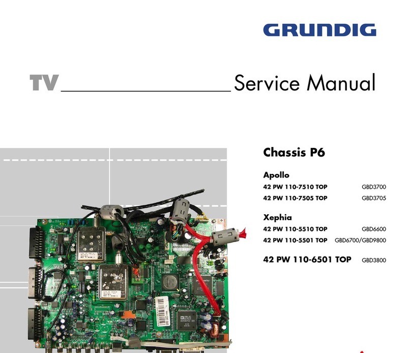
Grundig AGANTO 40 User manual

Materialnummer/Part Number 720100486000
Änderungen vorbehalten/Subject to alteration
H-S43 0305 • Printed in Germany
http://www.grundig.com
Zusätzlich erforderliche Unterlagen für den Komplettservice
Additionally required Service Documents for the Complete Service
Service
Manual
Sicherheit
Safety
Materialnr./Part No.
720108000001
TV Service Manual
Chassis PE-5
AGANTO 40
RPW 102-6410/8 Top
GBC0400
AGANTO 43
RPW 102-6410/8 Top
GBC3100
1 - 2
GRUNDIG Service Chassis PE-5
Inhaltsverzeichnis
Seite
Allgemeiner Teil ................................... 1-2…1-8
Allgemeine Hinweise .................................................................... 1-2
Technische Daten ........................................................................ 1-3
Bedienhinweise ............................................................................ 1-4
Service- und Sonderfunktionen .................................................... 1-6
Abgleich ................................................ 2-1…2-2
Platinenabbildungen
und Schaltpläne ................................. 3-1…3-42
Netzteil - JUT7.820.081 ............................................................... 3-1
Haupt-Platte - JUT7.820.083 ....................................................... 3-4
AV-Platte - JUT7.820.084 .......................................................... 3-10
Digital-Platte - JUT7.820.085 ..................................................... 3-13
Konvergenz Variante 1:
- Sensor-Platte - JUT7.820.098 ................................................. 3-23
- Covering-Platte - JUT7.820.071 .............................................. 3-24
Konvergenz Variante 2:
- Konvergenz-Platte - JUT7.820.203 ......................................... 3-27
Scan-Platte - JUT7.820.082 ....................................................... 3-30
Videotext-Platte - JUT7.820.087 ................................................ 3-36
Y-R-Platte - JUT7.820.182 ......................................................... 3-38
VM-Verstärker-Platte (R) - JUT7.820.151 .................................. 3-38
Y-G-Platte - JUT7.820.183 ........................................................ 3-39
VM-Verstärker-Platte (G) - JUT7.820.152 ................................. 3-39
Y-B-Platte - JUT7.820.184 ......................................................... 3-40
VM-Verstärker-Platte (B) - JUT7.820.153 .................................. 3-40
IR-Platte - JUT7.820.091 ........................................................... 3-41
CAV-Platte - JUT7.820.237 ....................................................... 3-41
Keyboard - JUT7.820.185 .......................................................... 3-42
LED-Platte - JUT7.820.186 ........................................................ 3-42
Explosionszeichnung und
Ersatzteillisten ...................................... 4-1…4-5
GB
D
Es gelten die Vorschriften und Sicherheitshinweise
gemäß dem Service Manual "Sicherheit", Material-
nummer 720108000001, sowie zusätzlich die eventu-
ell abweichenden, landesspezifischen Vorschriften!
The regulations and safety instructions shall be valid
as provided by the "Safety" Service Manual, part
number 720108000001, as well as the respective
national deviations.
Table of Contents
Page
General Section .................................... 1-2…1-8
General Notes .............................................................................. 1-2
Technical Data ............................................................................. 1-3
Operating Hints (only German) .................................................... 1-4
Service and Special Functions..................................................... 1-6
Adjustment ........................................... 2-1…2-2
Layout of the PCBs
and Circuit Diagrams ......................... 3-1…3-42
Mains Unit - JUT7.820.081 .......................................................... 3-1
Main PCB - JUT7.820.083 ........................................................... 3-4
AV PCB - JUT7.820.084 ............................................................ 3-10
Digital PCB - JUT7.820.085 ....................................................... 3-13
Convergence Variant 1:
- Sensor PCB - JUT7.820.098 ................................................... 3-23
- Covering PCB - JUT7.820.071 ................................................ 3-24
Convergence Variant 2:
- Convergence PCB - JUT7.820.203 ......................................... 3-27
Scanning PCB - JUT7.820.082 .................................................. 3-30
Teletext PCB - JUT7.820.087 .................................................... 3-36
Y-R PCB - JUT7.820.182 .......................................................... 3-38
VM Amplifier PCB (R) - JUT7.820.151 ...................................... 3-38
Y-G PCB - JUT7.820.183.......................................................... 3-39
VM Amplifier PCB (G) - JUT7.820.152 ...................................... 3-39
Y-B PCB - JUT7.820.184 .......................................................... 3-40
VM Amplifier PCB (B) - JUT7.820.153 ....................................... 3-40
Remote PCB - JUT7.820.091 .................................................... 3-41
CAV PCB - JUT7.820.237 ......................................................... 3-41
Keyboard - JUT7.820.185 .......................................................... 3-42
LED PCB - JUT7.820.186 .......................................................... 3-42
Exploded View and
Spare Parts Lists .................................. 4-1…4-5
General Section
General Notes
Before opening the cabinet disconnect the mains plug!
Attention: Observe the ESD safety regulations
Wiring
Before disconnecting any leads and especially the earth connecting
leads observe the way they are routed to the individual assemblies like
the chassis, mains switch panel, keyboard control panel, picture tube
panel, deflection unit, loudspeaker and so on. On completion of the
repairs the leads must be laid out as originally fitted at the factory to
avoid later failures or disturbances.
Carrying out Measurements
When making measurements on semi-conductors with an oscillo-
scope, ensure that the test probe is set to 10:1 dividing factor. If the
previous measurement was made on AC input, please note that the
coupling capacitor in the oscilloscope will be charged. Discharge via
the item being checked can damage the components.
Measured Values
The measured values given in the circuit diagrams are approximates!
Allgemeiner Teil
Allgemeine Hinweise
Vor dem Öffnen des Gehäuses zuerst den Netzstecker ziehen!
Achtung: ESD-Vorschriften beachten
Leitungsverlegung
Bevor Sie die Leitungen und insbesondere die Masseleitungen lösen,
muss die Leitungsverlegung zu den einzelnen Baugruppen beachtet
werden. Nach erfolgter Reparatur ist es notwendig, die Leitungs-
führung wieder in den werkseitigen Zustand zu versetzen um evtl.
spätere Ausfälle oder Störungen zu vermeiden.
Durchführen von Messungen
Bei Messungen mit dem Oszilloskop an Halbleitern sollten Sie nur
Tastköpfe mit 10:1 - Teiler verwenden. Außerdem ist zu beachten,
dass nach vorheriger Messung mit AC-Kopplung der Koppelkonden-
sator des Oszilloskops aufgeladen sein kann. Durch die Entladung
über das Messobjekt können Bauteile beschädigt werden.
Messwerte
Bei den in den Schaltplänen angegebenen Messwerten handelt es
sich um Näherungswerte!
Chassis PE-5GRUNDIG Service
1 - 3
Technische Daten / Technical Data
ARGANTO 40
Bild
RPW 102-6410/8 TOP
Bildröhre
Bildschirmdiagonale / sichtbares Bild
4 verschiedene Formatumschaltungen
Geschwindigkeitsmodulation (SVM) / Dynamischer Focus
cm
Rückprojektion
102 / 102 (16:9)
•
–
100-Hertz-Technik/ Digital-Reference-Technik
Erhöhte Farbcontourschärfe (CTI)
Bildschärfeeinstellung / Kammfilter
Electronic
•/•
•
•/•
Automatische Senderprogrammierung ATS
Multibildanzeige (Mosaic Picture)
PAT – geteilter Bildschirm (Bild/Text)
Bild-im-Bild (2-Tuner-PIP)
•
–
–
•
PAP – geteilter Bildschirm (Bild/Bild)
P2AT – Bild/Bild und Text
g
leichzeiti
g
Zahlenschloss
Programm-Speicherplätze TV / AV
–
–
•
99 / 6
Videotext / Seiten-Speicher
TV-Standard
Infrarot-Fernbedienung
Ton
•/ 100
BG, I, DK/K', L/L', PAL, SECAM
über AV: NTSC 4.43 + 3.58 MHz.
A2 für B/G/D/K, Nicam 5.58 MHz
(BG, L) + 6.52 MHz (I)
RC 40 C
Stereo-/Zweikanalton-Empfang
Musikleistung / Sinusleistung
Stereo wide
Kopfhörer-Lautstärke getrennt regelbar
Watt
•/•
2-Kanal 22 / 14
•
–
Kopfhörer-Tonkanalwahl bei Zweikanalton
Lautsprecher
Anschlüsse / Buchsen
S-Video-Eingang (Hosiden) für Camera-Recorder
–
2 Breitband frontal
• (vorne + hinten)
Euro-AV-Buchse / davon S-Video tauglich
Cinch-AV für Camera-Recorder / Kopfhörer-Buchse
Audio-Stereo-Ausgang für HiFi-Anlage
Netzteil
3x / 1
• (seitlich + hinten) /• (Ø 3,5 mm)
•
Spannung (Regelbereich), Frequenz 50/60 Hz
Leistungsaufnahme im TV-Betrieb / Standby
Gewicht ca. kg
Abmessungen ca. (Breite x Höhe x Tiefe)
V~
Watt
220 - 240
230 / 1
ca. kg
ca. cm
48
94 x 90 x 49
Technische Angaben ohne Gewähr.
ARGANTO 43
RP 110-6410/8 TOP
Rückprojektion
110 / 110 (4:3)
•
–
•/•
•
•/•
•
–
–
•
–
–
•
99 / 6
•/ 100
BG, I, DK/K', L/L', PAL, SECAM
über AV: NTSC 4.43 + 3.58 MHz.
A2 für B/G/D/K, Nicam 5.58 MHz
(BG, L) + 6.52 MHz (I)
RC 40 C
•/•
2-Kanal 22 / 14
•
–
–
2 Breitband frontal
• (vorne + hinten)
3x / 1
• (seitlich + hinten) /• (Ø 3,5 mm)
•
220 - 240
230 / 1
48
104,5 x 121,0 x 65,0
Chassis PE-5GRUNDIG Service
1 - 4
Bedienhinweise Dieses Kapitel enthält Auszüge aus der Bedienungsanleitung.
Weitergehende Informationen entnehmen Sie bitte der gerätespezifischen Bedienungsanleitung, deren Materialnummer Sie in der entsprechenden Ersatzteilliste finden.
Chassis PE-5GRUNDIG Service
1 - 5
Chassis PE-5GRUNDIG Service
1 - 6
Service- und Sonderfunktionen
Nicht beschriebene Einstellwerte sind werkseitig abgeglichen
und dürfen im Servicefall nicht verstellt werden!
Tastenfunktionen
P+/P- Menü-Zeile (Menüpunkt) wählen
V+/V- Wert ändern
Service-Mode aktivieren
–Lautstärke auf "0" reduzieren.
–Taste "MUTE" drücken und gedrückt halten. Wenn das Mute-Zei-
chen am Bildschirm gelb wird, zusätzlich Taste "MENU" (Nahbe-
dientaste) drücken.
Am Bildschirm wird die Softwareversion angezeigt z.B.: "S-Mode
PE5 - M - V4.04 04-01-29"
Mit der Taste "MENU" können die einzelnen Menüs aufgerufen wer-
den.
Einstellungen speichern
–Taste "RECALL" drücken.
Service-Mode beenden
–Taste "STILL" drücken.
Menupunkt / Parameter Item
[MENU 01]
Einstellwert / Default Value
Arganto 40 Arganto 43
V-AMP (Frame)
V-SHIFT (Frame Center)
V- LINEARITY (Frame Linearity)
S-COR (Frame S Adjust)
24
87
56
76
21
32
15
30
V-DF- PHASE (Frame Dynamic Focus Phase)
V-DF- AMP (Frame Dynamic Focus Breadth)
EW-WIDTH (Horizontal)
H-SHIFT (Horizontal Center)
4
7
4
7
31
52
32
59
EW-PARAW (Pincushion Distortion)
EW-TRAP (Trapezium Distortion)
ONLY ENG
OP 16-9
12
44
16
57
OFF OFF
OFF
OSD-XPOS
[MENU 02]
DRIVE-R
DRIVE-B
28H
0FH
1EH
12H
26H
R- CUT
G- CUT
B- CUT
BUS STOP ON( Bus switch)
DBH
60H
BDH
60H
B0H
OFF
BCH
OFF
FIRST POWER ON( Default)
SUB BRIGHT (Side Brightness)
Y-DELAY(PAL Y Delay)
SECAM-Y-DELAY(SECAM Y Delay)
OFF
16
OFF
26
8
0
8
0
NTSC-Y-DELAY (NTSC Y Delay)
VSM-PHASE
VSM-MAX
BBK-OFFSET
0
5
0
5
04H
50H
04H
50H
[MENU 03]
bright
Contrast
Color
80 50
90
50
50
50
OSD-XPOS
AD9883-V
AD9883-Y
AD9883-U
28H
6FH
28H
7EH
42H
6AH
51H
7EH
PW-58
PW-5C
PAL-59
PAL-5D
80H
F7H
8H
F7H
11H
6DH
11H
6DH
NTSC-59
NTSC-5D
10H
59H
10H
59H
Bemerkung /Remark
siehe Geometrie-Einstellungen/see geometry adjustments
Vorgabe Wert / default value
siehe Geometrie-Einstellungen/see geometry adjustments
Vorgabe Wert / default value
siehe Weißwert-Einstellungen/see white level adjustment
siehe Schwarzwert-Einstellungen/see black level adjustment
Vorgabe Wert / default value
Service and Special Functions
Settings not mentioned in this description are pre-set at the
factory and must not be readjusted in the case of repair!
Functions of the Buttons
P+/P- Call up te dialogue line (point of menu)
V+/V- Changing the settings
Calling up the Service Mode
–Reduce the volume to "0".
–Press button "MUTE" and hold depressed. Additionally press but-
ton "MENU" (on the TV) when the mute sign on the screen is go-
ing to be yellow. The software version is shown on the screen
e.g. "S-Mode PE5 - M - V4.04 04-01-29"
The different menus can be called up with button "MENU".
Store the Settings
–Press button "RECALL".
Exit the Service Mode
–Press button "STILL".
Chassis PE-5GRUNDIG Service
2 - 1
Abgleich
Nicht beschriebene Einstellwerte sind werkseitig abgeglichen
und dürfen im Servicefall nicht verstellt werden!
Alle Einstellungen in betriebswarmem Zustand durchführen.
Tastenfunktionen
P+/P- Menü-Zeile (Menüpunkt) wählen
V+/V- Wert ändern
Service-Mode aktivieren
– Lautstärke auf "0" reduzieren.
– Taste "MUTE" drücken und gedrückt halten. Wenn das Mute-Zei-
chen am Bildschirm gelb wird, zusätzlich Taste "MENU" (Nahbe-
dientaste) drücken. Mit Taste "MENU" können die einzelnen Me-
nüs aufgerufen werden.
Einstellungen speichern
– Taste "RECALL" drücken.
Service-Mode beenden
– Taste "STILL" drücken.
Geometrie-Einstellungen
Grobeinstellung:
- Geometrie-Testbild einspeisen.
- Grün ist Referenz.
- Service-Mode aktivieren.
- Menü 01 mit Taste "MENU" auswählen
- Geometriewerte nach Testbild einstellen.
Feineinstellung:
- Service-Mode aktivieren.
- Taste drücken -> Gittertestbild wird eingeblendet.
- Taste AV 2x drücken -> Anzeige "Fine".
- Mit Taste grünes Gitter auswählen.
- Mit Taste "Grün" grünen Cursor auswählen (nur grüne Farbe ab-
gleichen!).
- Mit Tasten P+,V+, P-, V- die abzugleichende Stelle auswählen
(konzentrisch von innen nach aussen).
- Mit Taste (Taste PIP-Standbild) Einstellpunkt aktivieren (Cur-
sor wird weiß).
- Mit Tasten P+,V+, P-, V- gerade Gitterlinien einstellen.
-
Mit Taste Einstellpunkt deaktivieren (Cursor in Abgleichfarbe).
- Alle nötigen Abgleichpunkte (jeweils nur Grün) einstellen. Auch
Abgleichpunkte, die ausserhalb des sichtbaren Bildbereichs lie-
gen können eingestellt werden.
- Mit Taste "Recall" speichern.
- Mit Taste "EXIT" zurück in den Service-Mode.
Weißwert-Einstellung
- Weiß-Bild einspeisen.
- Service-Mode aktivieren.
- Menü 02 mit Taste "MENU" auswählen
- DRIVE-R und DRIVE-B so einstellen, dass das Bild unbunt ist.
Schwarzwert-Einstellung
- Schwarz-Bild einspeisen.
- Service-Mode aktivieren.
- Menü 02 mit Taste "MENU" auswählen
- R-CUT, G-CUT und B-CUT so einstellen, dass das Bild unbunt ist.
Konvergenz-Einstellungen
Vor dem Konvergenzabgleich muss gegebenenfalls die Geometrie-
Einstellung durchgeführt werden.
- Taste "SMART FOCUS" (seitlich rechts am Gerät unter der Klap-
pe) drücken. -> Automatischer Abgleich.
- Service-Mode aktivieren.
- Taste drücken -> Gittertestbild wird eingeblendet.
- Taste AV 2x drücken -> Anzeige "Fine"
- Mit Taste "Grün" die Farbe auswählen die abgeglichen werden
soll (nur rote und blaue Farbe abgleichen!).
- Mit Tasten P+, V+, P-, V- die abzugleichende Stelle auswählen
(konzentrisch von innen nach aussen).
- Mit Taste (Taste links unten auf Fernbedienung) Einstell-
punkt aktivieren (Cursor wird weiß).
- Mit Tasten P+, V+, P-, V- die Linien zur Deckung bringen.
- Mit Taste Einstellpunkt deaktivieren (Cursor in Abgleichfarbe).
- Alle nötigen Abgleichpunkte (jeweils für Rot und Blau) einstellen.
Auch die Abgleichpunkte, die ausserhalb des sichtbaren Bildbe-
reichs liegen können eingestellt werden.
- Mit Taste "Recall" speichern.
- Mit Taste "EXIT" zurück in den Service-Mode.
Adjustment
Settings not mentioned in this description are pre-set at the
factory and must not be readjusted in the case of repair!
All adjustment must be done at operating temperature.
Functions of the Buttons
P+/P- Call up te dialogue line (point of menu)
V+/V- Changing the settings
Calling up the Service Mode
– Reduce the volume to "0".
– Press button "MUTE" and hold depressed. Additionally press but-
ton "MENU" (on the TV) when the mute sign on the screen is go-
ing to be yellow. The different menus can be called up with button
"MENU".
Store the Settings
– Press button "RECALL".
Exit the Service Mode
– Press button "STILL".
Geometry Adjustments
Preadjustment:
- Feed in a geometry test pattern.
- Green is reference.
- Start service mode.
- Select menu 01 with button "MENU".
- Adjust all geometry values according to the test pattern.
Fine adjustment:
- Start service mode.
- Press button -> white grid pattern appears.
- Press button AV twice -> "Fine" is displayed.
- With button select the green grid.
- With button "Grün" select a green cursor (only green color has to
be adjusted!).
- With buttons P+,V+, P-, V- select the adjustable position (con-
centrical from the centre to the borders).
- With button (button PIP freece image) activate the adjust-
ment point (cursor becomes white).
- With buttons P+,V+, P-, V- adjust for straight grid lines.
- With button deactivate the adjustment point (cursor beco-
mes adjusting color).
- Adjust all necessary points (only green color). Adjusting points
outside the viewable area can also be adjusted.
- Store adjustments with button "Recall".
- With button "EXIT" switch back to service mode.
White Level Adjustment
- Feed in a white pattern.
- Start service mode.
- Select menu 02 with button "MENU".
- Adjust DRIVE-R and DRIVE-B for an achromatic picture.
Black Level Adjustment
- Feed in a black pattern.
- Start service mode.
- Select menu 02 with button "MENU".
-
Adjust R-CUT, G-CUT and B-CUT for an achromatic picture.
Convergence Adjustment
If neccessary geometry adjustment should be done before conver-
cence adjustment.
- Press button "SMART FOCUS" (at right side of the set under a
flap). -> Automatic adjustment.
- Start service mode.
- Press button -> white grid pattern appears.
- Press button AV twice -> "Fine" is displayed.
- With "Green" button the color which should be adjusted can be
selected (only red and blue color must be adjusted!).
- With buttons P+, V+, P-, V- select the adjustable position (con-
centrical from the centre to the borders).
- With button (button PIP freece image) activate the adjust-
ment point (cursor becomes white).
- With buttons P+, V+, P-, V- bring the lines on top of each other.
- With button deactivate the adjustment point (cursor beco-
mes adjusting color).
- Adjust all necessary points (each for red and blue color). Adju-
sting points outside the viewable area can also be adjusted.
- Store adjustments with button "Recall".
- With button "EXIT" switch back to service mode.
Chassis PE-5GRUNDIG Service
2 - 2
Konvergenztestbild
schwarz:
sichtbarer Bildbereich
rot:
aktueller Cursor
rosa:
Abgleichpositionen
grau:
Abgleichlinien ausserhalb
des sichtbaren Bereichs
Convergence
test pattern
black:
viewable pattern area
red:
current cursor
pink:
adjustment positions
grey:
adjustment lines out of
the viewable pattern area
Menupunkt / Parameter Item
[PHASE]
Einstellwert / Default Value
Arganto 40 Arganto 43
VBLK04V
VBLK04P
V10FSET
DAC2P
0000H
0000H
0000H
0000H
0000H
0000H
0000H
0000H
DAC1P
COARSEP
FINEP
TPOPH
0000H
0F14H
0000H
0000H
045CH
0079H
045CH
0078H
STARTLIN
V1CNTUP
TPOPV
V1DLY
0020H
0346H
0020H
0346H
0009H
0000H
0009H
0001H
[COARSE]
V1H2BV
V1H1BV
V1BV
032DH 02D3H
00C8H
0064H
00A0H
0050H
H1BV
DCBV
V2H2BH
V2H1BH
03EEH
03F0H
03FEH
03DCH
0000H
0000H
0014H
03F5H
V1BH
H2BH
H1BH
DCBH
03F6H
02C9H
0000H
0283H
0046H
0099H
0013H
00EAH
V1H2GV
V1H1GV
V1GV
H1GV
0341H
000AH
02B5H
0000H
006EH
000CH
0064H
03FEH
DCGV
V2H2GH
V2H1GH
V1GH
03DCH
0000H
03E4H
0000H
0000H
03FEH
03F5H
03FFH
H2GH
H1GH
DCGH
V1H2RV
0000H
0000H
0000H
03FFH
03E9H
0337H
0001H
034BH
V1H1RV
V1RV
H1RV
DCRV
03AFH
0078H
035FH
003CH
0002H
03F8H
0000H
03E7H
V2H2RH
V2H1RH
V1RH
H2RH
0000H
0000H
03D7H
03EBH
03EDH
00F0H
0000H
01A4H
H1RH
DCRH
03EBH
039AH
0033H
0340H
Bemerkung /Remark
Vorgabe Wert / default value
Einstellwerte "PHASE"/"COARSE"
Nebenstehende Menüpunkte sind werksei-
tig abgeglichen und dürfen nicht verstellt
werden. Im Servicefall müssen nebenste-
hende Werte eingestellt werden.
- Service-Mode aktivieren.
- Taste drücken -> Gittertestbild wird
eingeblendet. Menü"PHASE" ist aktiv.
- Mit Tasten P+ oder P- Menüpunkt aus-
wählen
- Mit Tasten V+ oder V- Werte ändern.
- Taste "AV" einmal drücken. Menü
"COARSE" ist aktive.
- Mit Tasten P+ oder P- Menüpunkt aus-
wählen
- Mit Tasten V+ oder V- Werte ändern.
Parameter "PHASE"/"COARSE"
Beneth parameter items are pre-set at the
factory and must not be readjusted. In case
of repair beneth default values must be ad-
justed.
- Start Service Mode.
- Press button -> grid pattern appears.
Menu "PHASE" is activated.
- Press button P+ or P- to select the menu
item.
- Press button V+ or V- to change the va-
lues.
- Press button "AV" once. Menu "COARSE"
is activated.
- Press button P+ or P- to select the menu
item.
- Press button V+ or V- to change the va-
lues.
GRUNDIG Service Chassis PE-5
3 - 1
Platinenabbildungen und Schaltpläne / Layout of PCBs and Circuit Diagrams
Netzteil / Mains Unit - JUT7.820.081
GRUNDIG Service Chassis PE-5
3 - 2
PE-5 CHASSIS (2)
2003.7.5
to XP304
Scanning PCB
P. 3-32
to XP303
Scanning PCB
P. 3-32
to XP302
Scanning PCB
P. 3-32
to XP301
Scanning PCB
P. 3-32
Netzteil / Mains Unit - JUT7.820.081
GRUNDIG Service Chassis PE-5
3 - 3
Netzteil / Mains Unit - JUT7.820.081
GRUNDIG Service Chassis PE-5
3 - 4
to XGP03
VM (G) PCB
P. 3-39
P. 3-36 P. 3-36
to XP901
AV PCB
P. 3-10
to XP902
AV PCB
P. 3-10
to XP903
AV PCB
P. 3-10
to XP500
Digital PCB
P. 3-16
to XP501
Digital PCB
P. 3-16
Haupt-Platte / Main PCB - JUT7.820.083
GRUNDIG Service Chassis PE-5
3 - 5
PE-5 CHASSIS (4)
2003.7.5
to XP203k
CAV PCB
P. 3-41
to XP206k
CAV PCB
P. 3-41
to XP206k
K PCB
P. 3-42
to XP01
Remote PCB
P. 3-41
to XP318
Scan PCB
P. 3-30
to XP316
Scan PCB
P. 3-32
to XP317
Scan PCB
P. 3-32
to XP319
Scan PCB
P. 3-30
Haupt-Platte / Main PCB - JUT7.820.083
GRUNDIG Service Chassis PE-5
3 - 6
3
16
P
CB
3
2
to XGP01
Y-G PCB
P. 3-39
to XSC01
Covering PCB
P. 3-24
to XSC02
Convergence PCB
P. 3-27
to XSC03
Convergence PCB
P. 3-27
to XSC03
Convergence PCB
P. 3-27
to XSC05
Convergence PCB
P. 3-27
to XSC02
Covering PCB
P. 3-24
to XSC04
Covering PCB
P. 3-25
to XSC03
Covering PCB
P. 3-24/25
3
17
P
CB
3
2
to XP304
Scanning PCB
P. 3-32
Haupt-Platte / Main PCB - JUT7.820.083
GRUNDIG Service Chassis PE-5
3 - 7
Haupt-Platte / Main PCB - JUT7.820.083
GRUNDIG Service Chassis PE-5
3 - 8
Haupt-Platte / Main PCB - JUT7.820.083
GRUNDIG Service Chassis PE-5
3 - 9
Haupt-Platte / Main PCB - JUT7.820.083
GRUNDIG Service Chassis PE-5
3 - 10
PE-5 CHASSIS (1)
2003.7.5
to XP201 Main PCB P. 3-4to XP202 Main PCB P. 3-4
to XP203
Main PCB
P. 3-4
AV-Platte / AV PCB - JUT7.820.084
GRUNDIG Service Chassis PE-5
3 - 11
AV-Platte / AV PCB - JUT7.820.084
GRUNDIG Service Chassis PE-5
3 - 12
AV-Platte / AV PCB - JUT7.820.084

This manual suits for next models

7

Other Grundig TV manuals

Grundig 40 GBF 5000 User manual

Grundig

Grundig 40 GBF 5000 User manual

Grundig CUC 2103 User manual

Grundig

Grundig CUC 2103 User manual

Grundig 65 GUW 8960 User manual

Grundig

Grundig 65 GUW 8960 User manual

Grundig 22 VLE 4520 BM User manual

Grundig

Grundig 22 VLE 4520 BM User manual

Grundig CUC 6460 User manual

Grundig

Grundig CUC 6460 User manual

Grundig 49 VLE 6725 BP User manual

Grundig

Grundig 49 VLE 6725 BP User manual

Grundig T 51-830 Multi/ICN User manual

Grundig

Grundig T 51-830 Multi/ICN User manual

Grundig 32 GFB 6826 User manual

Grundig

Grundig 32 GFB 6826 User manual

Grundig CUC 1822 User manual

Grundig

Grundig CUC 1822 User manual

Grundig Berlin SE 7027/8 PIP User manual

Grundig

Grundig Berlin SE 7027/8 PIP User manual

Grundig Fire TV 32 VLE 6010 User manual

Grundig

Grundig Fire TV 32 VLE 6010 User manual

Grundig 72010-800.00 User manual

Grundig

Grundig 72010-800.00 User manual

Grundig APOLLO 42 PW 110-7505 TOP User manual

Grundig

Grundig APOLLO 42 PW 110-7505 TOP User manual

Grundig 32 VLC 6010 C User manual

Grundig

Grundig 32 VLC 6010 C User manual

Grundig GBD4200 User manual

Grundig

Grundig GBD4200 User manual

Grundig 32 GFB 6827 User manual

Grundig

Grundig 32 GFB 6827 User manual

Grundig 75 GHU 7970 B User manual

Grundig

Grundig 75 GHU 7970 B User manual

Grundig 48 VLE 666 BL User manual

Grundig

Grundig 48 VLE 666 BL User manual

Grundig 32 GEH 6600B User manual

Grundig

Grundig 32 GEH 6600B User manual

Grundig 19 VLC 2001 C User manual

Grundig

Grundig 19 VLC 2001 C User manual

Grundig VENTI II series User manual

Grundig

Grundig VENTI II series User manual

Grundig 40 GEF 6930 A Reference guide

Grundig

Grundig 40 GEF 6930 A Reference guide

Grundig CUC 1894 User manual

Grundig

Grundig CUC 1894 User manual

Grundig 55 VLE 6725 BP User manual

Grundig

Grundig 55 VLE 6725 BP User manual

Popular TV manuals by other brands

Philips OLED876 Series quick start guide

Philips

Philips OLED876 Series quick start guide

Sony BRAVIA XR XR-98X9 L Series Setup guide

Sony

Sony BRAVIA XR XR-98X9 L Series Setup guide

Dynex DX-32L100A11 Guide d'installation rapide

Dynex

Dynex DX-32L100A11 Guide d'installation rapide

Panasonic TC-21FG20R Service manual

Panasonic

Panasonic TC-21FG20R Service manual

Philips 50PFL4901 quick start guide

Philips

Philips 50PFL4901 quick start guide

Sharp 21K-FG1M Operation manual

Sharp

Sharp 21K-FG1M Operation manual

Panasonic tx-34p180b Service manual

Panasonic

Panasonic tx-34p180b Service manual

Sony KV-BZ212 operating instructions

Sony

Sony KV-BZ212 operating instructions

Panasonic Omnivision PV-C2062 operating instructions

Panasonic

Panasonic Omnivision PV-C2062 operating instructions

Mitsubishi Electric WD-60C9 Specifications

Mitsubishi Electric

Mitsubishi Electric WD-60C9 Specifications

LG 29FX4BL- owner's manual

LG

LG 29FX4BL- owner's manual

GPX TD3222P quick start guide

GPX

GPX TD3222P quick start guide

Telefunken TTV-299 owner's manual

Telefunken

Telefunken TTV-299 owner's manual

Sony KV-14LT1B Service manual

Sony

Sony KV-14LT1B Service manual

Hitachi 32LD9800TA user manual

Hitachi

Hitachi 32LD9800TA user manual

Sharp LC-15C2HA Operation manual

Sharp

Sharp LC-15C2HA Operation manual

Hisense A6G Series user manual

Hisense

Hisense A6G Series user manual

Samsung Serif QE55LS01R E-manual

Samsung

Samsung Serif QE55LS01R E-manual

manuals.online logo
manuals.online logoBrands
  • About & Mission
  • Contact us
  • Privacy Policy
  • Terms and Conditions

Copyright 2025 Manuals.Online. All Rights Reserved.