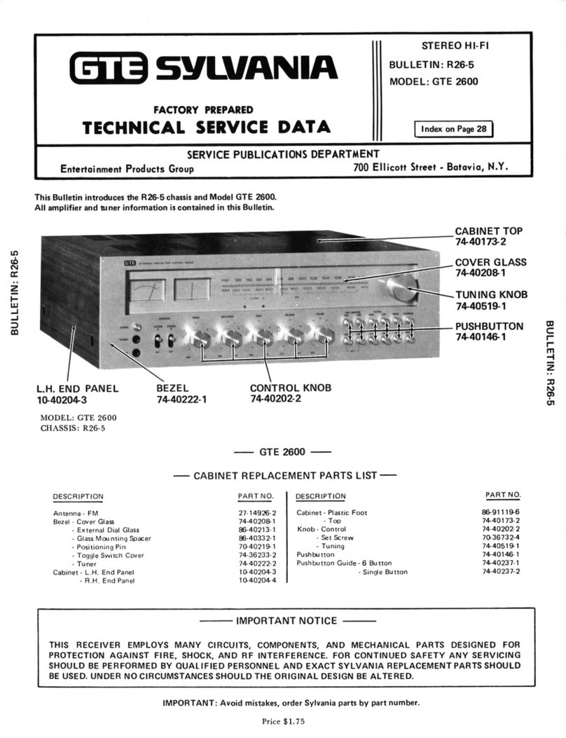
GTE 2400 User manual

GTE
AUDIO
COMPONENTS
OPERATING
INSTRUCTIONSFOR
MODEL
2 4 00

INTRODUCTION
Youaretheownerofoneofthemostsophisticated
andversatileaudioinstrumentsonthemarket.To
obtainthefullsoundqualityfromyourstereoreceiver,
itmustbecombinedwithspeakersystemsandother
accessoriesofequallyhighstandards.YourGTE
dealerwillbehappytoadviseyouwhenselecting
accessories.
Beforeoperatingthisreceiver,carefullyreadthe
instructionscontainedinthisbooklet.Itis
recommendedthatthisbookletbekeptwiththe
receiverforfuturereference.
TABLE
OFCONTENTSPage
Introduction
2
Features
TunerSection3
AmplifierSection3
MuteCircuit3
PhaseQ-4 3
ProtectiveCircuits3
Stereo
System
SetUp4
Speaker
System
Connection
4
Antenna
Connections
5
Power
Source
5
Component
Connections
6
Front
Panel8
Sound
System
Operation
Aux10
AMReception10
FMReception10
Phono10
Microphone10
TapePlay10
TapeRecording10
RecordingTape
1
ontoTape2 10
Specifications
11
Care
of
Cabinet
12
Consumer
Relations
12
WARNING:
TOAVOIDPOSSIBLEFIREORSHOCK
HAZARD,
NEVEREXPOSETHIS
UNITTORAINORMOISTURE.IFSUCHEXPOSUREOCCURS,REMOVETHEPLUG
FROMTHEELECTRICALOUTLETANDHAVETHEEXPOSEDUNITCHECKEDBYA
COMPETENTSERVICETECHNICIAN.
2

TUNERSECTION
•FMFrontEndusesa FETina groundedgate
configurationlorexcellentsensitivityandsuperb
overloadrejection
•PLLstereomultiplexcircuitryusinganintegrated
circuittorlowdistortionandhighstabilityproviding
excellentstereoseparationoverlongtermuse.
•IFamplifiersectionutilizesceramicfilterswhich
provideexcellentimageandalternatechannel
rejection.
•Centertuneandsignalstrengthmetersmake
possibleoutstandingtuningaccuracy.
AMPLIFIER
SECTION
•Direct-coupledOCLcircuitryutilizinginput
dif-
ferentialmatchedtransistorpairsthroughtothe
complimentaryoutputtransistorsBecausethe
OCLcircuitryhasnooutputcapacitor,thepower
bandwidthinthelowfrequenciesisextended
beyondaudibility,providingmaximumlowfre-
quencyperformanceandexcellentdampening
characteristicsThecomplimentaryPNP-NPN
outputstagesalsoreducessignificantlythehigher
orderharmonicdistortionproducts,resultingin
cleanhighfrequencyreproduction.
•TonecontrolsutilizeBaxandallfeedbackcutboost
circuitryforpreciseadjustmentofbassandtreble
frequencies
•Phonopre-ampdistortionandnoisearekepttoa
minimumbyusinglownoisehighgaindevicesina
2stageDarlingtonpre-ampdesign.
MUTECIRCUIT
Thisreceiverincorporatesa FETaudiomutecircuit
whichisactivatedbytheFunctionButtonsandwhen
thereceiveristurnedonandoff.Attenuationofthe
audiosignalpreventsannoyingclicksandpops.
PHASEQ-4STEREO
Nowyoucanexperiencetotaldimensionalsound
.. .soundfromeverycorneroftheroom.TheGTE
PhaseQ-4matrixsystem,withfourspeakersinthe
sameroom,givestheeffectoffour-channelsound.In
almostanylivelisteningsituation,youhearsounds
froma numberofdirections.Soundfromthefrontfor
example,isreflectedoffrearandsidewalls.GTE's
PhaseQ-4approximatesa livelisteningsituation,
givingyoua newdimensioninstereosound.This
remarkableeffectisachievedwiththespeakersinthe
positionsindicatedinthediagram.Noticetherear
speakersareclosertothelistenerthanthemain
speakers.Thisarrangementcompensatesfora
slightlyloweraudiolevelfromtherearspeakers.
NOTE:
Thissystemisdesignedtooperatewithstereo
orfour-channelmatrixprogrammaterialonly.When
listeningtomonauralprogramming,thePQ-4
speakersshouldbeturnedOFF.
PROTECTIVECIRCUITS
Yourreceiverincorporatesfourprotectivesystemsto
guardagainstabnormaloperatingconditionsthat
couldcausedamagetothereceiverorspeakers.
*
Electronic
Current
Limiting
Protectstheamplifierfromimproperlyconnected
speakers.Iftheoutputisshortedorexcessively
loaded,
theamplifierwillautomaticallylimitthe
outputsignaltosafelevels.
•
Thermal
Switch
Willshutoffthepowersupplytotheamplifier
sectioniftheinternaltemperaturebecomes
excessive.Theunitwillautomaticallycomeback
onwhenithascooled
•AC
Power
Overload
Protection
Thisprotectionisprovidedbya FUSEwhichwill
shutoffyourreceiverincaseofanACpower
overload
*
Electronic
Speaker
Protection
Providesspeakerprotectionincaseofcomponent
failureinthepoweramplifier.Thiselectronic
circuitwilldetectanyabnormalDCvoltageatthe
speakerterminalsandwillautomaticallyshutdown
thepoweramplifiersection.Normalsignalpower
capabilityoftheamplifierisnotimpairedbythis
circuit.
Ifallspeakersautomaticallyshutoffwhilethedial
remainslighted,turnyoursetOFF.Waitfor1
minuteandthenturnthesetbackON.Ifthe
speakersoperatemomentarilyandagainauto-
maticallyshutoff,unplugthesetfromtheelectrical
outletandconsultyourGTEdealer.
3
FEATURES

STEREOSYSTEMSETUP
•Wheninstallingandduringtheoperationofthis
receiver,caremustbetakennottocloseoffthe
ventarealocatedonthetopofthereceiver.One
inchminimumclearanceisrecommendedforsafe
andreliableperformance.
•Placementofyourspeakersystemswillvarywith
roomsize,acoustics,andpersonalpreference.
Thefollowinginformationwillassistyouinthefinal
placementofyourspeakersystems.
Generally,thespeakersystemsshouldbeplaced
atapproximatelyearlevelheight,andspacedat
leastsixtoeightfeetapart.Asthedistance
betweenspeakersystemsincreases,thestereo
separationbecomesmorepronounced.
Whenwiderspacingisused,anglethespeaker
systemsslightlysothattheprincipallisteningarea
intheroomiscovered.
•Witha highpowerstereosystem,improper
placementoftheturntablecanresultinacoustic
feedback(arumblingorhowlingsound).Acoustic
feedbackiscausedbyvibrationsfromtheloud
speakersreachingtheturntableandbeingre-
amplified.
Placingtheturntableona sturdyshelforcabinet,
andnotonorclosetoa speakercabinetwillreduce
theoccurenceoffeedback.
SPEAKER
SYSTEMCONNECTION
Threesetsofspeakerterminals(A,B & PQ-4)are
providedonthereceiverwhichallowthe
connectionofthreesetsofspeakers.Useno
smallerthan18gaugewiretoconnectspeakersto
outputterminals.Alwaysbesurepositiveand
negativeoutputsareconnectedtocorresponding
positiveandnegativeterminalsonthespeakers.
CAUTION:
BECAREFULTHATTHEWIRESDO
NOT"SHORT"EACHOTHEROUTATTHE
SPEAKERTERMINALS.
HelpfulHint:Mostlampcordor"ZIP"cordhasa
moldedridgealongonesidetoidentifypolarity.
Seeillustrationbelow.
•Speakerswitchesareconvenientlylocatedonthe
frontofthereceiversothatyoucanchangefrom
onespeakersystemtoanotherwithoutdiscon-
nectingandre-connectingaccessoryspeakers.
•Youcanlistenprivatelytoyourfavoritestereo
musicbypluggingaccessoryheadphonesintothe
built-instereophonejack.
Forrear(PQ-4)speakerstooperate,SystemA
SpeakerswitchandPQ-4switch(locatedonthe
rearofthereceiver)mustbeintheONposition.
HelpfulHint:WhenusingthePhaseQ-4matrix
system,
itisrecommendedthatfrontspeakersbe
connectedtoSPEAKERB terminalsandrear
speakerstoPQ-4terminals.Withspeakers
connectedinthismanner,youcanturnrear
speakersoffsimplybyswitchingSYSTEMA
SpeakerswitchOFF.
Whenremotespeakersareused,itisrecom-
mendedthatfrontspeakersbeconnectedto
SPEAKERA terminals,rearspeakerstoPQ-4
terminalsandremotespeakerstoSPEAKERB
terminals.Withspeakersconnectedinthis
manner,rearspeakerscanbeturnedoffbysliding
PQ-4switchOFF.
CAUTION:
CONNECTONLYSPEAKERSWHICH
ARE
RECOMMENDEDFORUSEWITH
AMPLI-
FIERSRATEDAT55WATTSORHIGHER.USE
OFSPEAKERSRECOMMENDEDFOR
AMPLI-
FIERSRATEDATLESSTHAN55WATTSMAY
RESULTINPERMANENTDAMAGETOTHE
SPEAKERS
ANDTHERECEIVERIFPLAYEDAT
HIGH
LEVELS.
4

AM
ANTENNACONNECTION
•SlideferriterodAMantennaassembly(contained
inseparatebag)intoholderandplug-inconnector.
AnExternalLongLineAMAntennamaybe
attachedbyconnectinglead-inwirefromantenna
torightAMANTENNAterminalandconnecting
ground(left)terminaltoa goodearthground,such
asa waterpipe.
NOTE:
TheAMferriterodmustremainattached
forproperoperation.
FMANTENNACONNECTIONS
•ConnectleadsfromtheFMdipoleantenna
(suppliedwithreceiver)tothe300OHMFM
ANTENNAterminals.
Toattacha 300OhmExternalFMAntenna,
connecttheleadsfromtheantennatothe300
OHMFMANTENNAterminals.
Ifa 75OhmExternalFMAntennaistobeused,
connectthecoaxialcabletothe75OHMFM
ANTENNAjack
NOTE:
UseonlyoneFMantennaeither75ohm
or300ohmatanyonetime
POWERSOURCE
Afterconnectingallcomponentstothereceiver,plug
inAClinecordtoa 120Volt,60Hertz(cycle)
alternatingcurrect(AC)only.Neverconnectthe
receivertoanelectricaloutlethavinga different
frequencyorvoltage.Permanentdamagetoyour
systemmayresult.
Note:
Ifyourreceiverwillnotoperateoritsuddenly
goesoff,checkfuse.Iffusehasburnedoutreplace
withfusehavingsameamperagerating.If
replacementfusealsoburnsout,consultyour
authorizedGTEdealer.
ANTENNA
CONNECTIONS
FM
OUTDOOR
ANTENNA
5

COMPONENT
NOTE:
Makeallantennaandcomponent
connectionsbeforeturningpowerON
PHONO
JACKS
Thetwophonoinputsallowfortheuseoftwo
turntables.
•SelecteitherthePHONOONEorTWOjacksand
plugturntablecablesintotheappropriateleftand
rightjacks.ConnectgroundwireunderPHONO
GROUNDterminal( V ).
•PHONOONEinputimpedancemaybeselectedfor
47kohm
aswellas100kohm.Checkcartridge
specificationsforimpedancevalue.
SlidePHONOONEswitchtoappropriateinput
impedance.PHONOTWOinputimpedanceis
47kohm
only.
AUX
JACKS
Plugtheoutputofaccessoryequipmentintotheap-
propriateleftandrightjacks.Typicalaccessoriesare:
•8-track,cassette,orreeltoreeltapeplaydeck.
•Microphoneormusicalinstrumentwithpre-
amplifier.
TAPE
JACKS
Thetwosetsoftapejacksallowfortheuseoftwo
tapedecks.
Record
•ConnecttherecordLINEINPUTjacksofthetape
decktotheTAPEONE(orTWO)RECORDjacks.
Play
•ConnecttheplaybackLINEOUTPUTjacksofthe
tapedecktotheTAPEONE(orTWO)PLAY.
PRE-AMP
Thepre-amplifiersignalsarerelayedfromthe
PRE-AMPjackstothe-AMPjacksbytheuseof
jumpers.Thesejumpersmaybereplacedwith
accessoryequipmentsuchas:
•EnvironmentalEqualizer— toshapefrequency
responsetosuitroomacoustics.
6

CONNECTIONS
•SlavePowerAmplifier— todrivemultiplespeaker
systems.
•CrossoverNetworkanda SlavePowerAmplifier—
toconvertreceivertobi-ampoperation.
CAUTION:
REMOVINGJUMPERSWITHPOWER
ONMAYRESULTINPERMANENTDAMAGETO
SPEAKERS
ANDRECEIVER.
Toconnectanenvironmentalequalizer:
•TurnpowerOFF.
•Removejumpers.
•PlugcablesfromPRE-AMPjackstoenvironmental
equalizerinputjacks.
•PlugcablesfromAMPjackstoenvironmental
equalizeroutputjacks.
•Checkchannelconnectionsforproperhook-up
beforeturningpowerON.
Toconnecta slavepoweramplifier:
•TurnpowerOFF.
•Removejumpers.
•Usinga commerciallyavailable"Y"connector,
connectleftchannel(L)PRE-AMPandAMPjacks
toleftchannel(L)slaveamplifierjack.
•Repeatabovesteptoconnectrightchannel.
•Checkchannelconnectionsforproperhook-up
beforeturningpowerON.
NOTE:
Youwillbeabletocontroltheslaveamplifier
throughthereceiverVOLUME,BALANCEandTONE
controls.
Toconnecta crossovernetworkanda slavepower
amplifier:
•TurnpowerOFF.
•Removejumpers.
•Plugcablefromleft(L)PRE-AMPjacktoleft
crossovernetworkinputjack.
•Plugcablefromleftchannellow-frequencysection
ofcrossovernetworktoleftchanneljackof
amplifierhavinghigherpowerrating.
•Plugcablefromleftchannelhigh-frequency
sectionofcrossovernetworktoleftchanneljackof
amplifierhavinglowerpowerrating.
•Repeatabovestepstoconnectrightchannel.
•Checkchannelconnectionsforproperhook-up
beforeturningpowerON.
NOTE:
Whenusinga crossovernetworkanda slave
poweramplifierforbi-ampoperation,youwillbeable
toutilizeboththereceiveramplifierandslave
amplifier;andbeabletocontrolboththroughthe
receiverVOLUME,BALANCEandTONEcontrols.
UNSWITCHEDACOUTLETS
Plugaccessorycomponentssuchasturntablesor
tapedecksintotheseoutlets.Theoutletsremainon
whenthereceiverpowerswitchisturnedoff.
SWITCHEDACOUTLET
Plugassociatedelectroniccomponentssuchasan
environmentalequalizerorslaveamplifierintothis
outlet.Thisoutletwillbeoffwhenthereceiverpower
isoff.
NOTE:
Donotusethisoutletforturntables,tape
decksorothermotordrivenaccessories.
WARNING:
TOAVOIDA POSSIBLESHOCK
HAZARD,
DONOTCONNECTANYACCESSORY
WHICHDOESNOTHAVEA MANUFACTURER
SUPPLIEDAUDIOOUTPUT
JACK.
7

FRONT
FM
DIAL—
INDICATESFMSTATIONFREQUENCIES
88TO108MHz
AM
DIAL
— INDICATESAMSTATION
FREQUENCIES520TO1630kHz.
FMMPXINDICATOR—LIGHTGLOWSWHENYOU
HAVETUNEDINA STEREOBROADCAST.
NOTE:
INDICATORWILLNOTLIGHTWHENMONO
BUTTONISDEPRESSEDEVENIFTUNEDTO
STEREOBROADCAST
FMTUNINGMETER— INDICATESBESTFM
TUNINGWHENPOINTERISCENTERED.
SIGNAL-STRENGTHMETER— INDICATESBEST
AMANDFMRECEPTIONWHENPOINTERISASFAR
RIGHTASPOSSIBLE.ITISALSOUSEFULFOR
ORIENTINGANTENNAFOROPTIMUMSIGNAL
STRENGTHONFM.
MIC
JACK
— FORMICROPHONEORMUSICAL
INSTRUMENTINPUT.
POWER— TOTURNRECEIVERONANDOFF.
PHONES
JACK
— TOPLUGINSTEREOHEAD-
PHONES.
SYSTEMA SPEAKERSWITCH— TOSELECT
SYSTEMA ANDPO-4SPEAKERSYSTEMS
SYSTEMB SPEAKERSWITCH— TOSELECT
SYSTEMB SPEAKERSYSTEM.
TREBLE—
TOCUTORBOOSTHIGHFREQUENCY
TONESSUCHASFLUTESORVIOLINS
BASS
— TOCUTORBOOSTLOWFREQUENCY
TONES,
SUCHASKETTLEDRUMSORORGAN
PEDALNOTES.
BALANCE
—TOADJUSTFOREQUALLEVELFROM
LEFTANDRIGHTSPEAKERS,TURNKNOB
CLOCKWISETOREDUCELEVELINLEFTCHANNEL.
COUNTERCLOCKWISETOREDUCELEVELINRIGHT
CHANNEL.
8

PANEL
LOG
SCALE—QUICKREFERENCETUNINGGUIDE
THATPROVIDESLOGSCALEREFERENCENUM-
BERSWHICHCANBEUSEDTORELOCATE
FAVORITESTATIONS.
TUNING—TOSELECTAM& FMSTATIONS.
MONO— ENGAGESSYSTEMFORMONAURAL
SOURCES.ITALSOSWITCHESFMTUNERTO
MONO;
THISWILLREDUCETHENOISEONWEAK
FMSTEREOSTATIONS
LOUDNESS—TOINCREASEBASSFREQUENCIES
FORPROPERTONALBALANCEATLOWLISTENING
LEVELS.
FM— TOENGAGESYSTEMFORFMRECEPTION.
FMMUTE— ELIMINATESINTERSTATIONNOISE
ANDWEAKNOISYFMSTATIONS.PUSHTOMUTE.
SHOULDYOUWISHTOSEARCHFORORLISTEN
TOWEAKSIGNALSTATIONSRELEASEMUTE
BUTTON.
AM
— TOENGAGESYSTEMFORAMRECEPTION.
AUX
— TOENGAGESYSTEMFORAUXILIARY
COMPONENTS.
HIGHANDLOWFILTERS— HIGHFILTERRE-
DUCESHIGHFREQUENCYTAPEHISS,RECORD
SCRATCHNOISEANDCUTSOFFFREQUENCIES
ABOVE10kHz.LOWFILTERREDUCESTURNTABLE
RUMBLEANDACOUSTICALFEEDBACK.
PHONOONEORTWO— TOENGAGESYSTEM
FORPHONOGRAPHPLAY.
MIC— TOENGAGESYSTEMFORMICROPHONE
USE.
TAPE
ONEANDTWO—TOENGAGESYSTEMFOR
ACCESSORYTAPEPLAYORTAPEMONITORING.
NOTE:
TAPEBUTTONSMUSTBERELEASED
FORFM,AM,PHONO,MIC,ORAUX
FUNCTIONS.
VOLUME—TOADJUSTAUDIOLEVEL,TURNKNOB
CLOCKWISETOINCREASEVOLUME.
NOTE:
ALWAYSSETVOLUMETOMIN"0"
POSITIONBEFORETURNINGONRE-
CEIVER.
9

SOUNDSYSTEMOPERATION
BeforeturningthepowerON,setcontrolsand
switchesasfollows:
•VOLUMEcontroltoMINposition.
•TREBLE,BASS,andBALANCEcontrolstocenter
(0)
position.
•SwitchappropriatespeakersystemON.See
"SpeakerSystemConnection."
•TAPEONEandTWObuttonstoOFF(unpushed)
position.
AUX
•Connectaccessoryunittorearofreceiver.See
"ComponentConnections".
•DepressAUXbutton.
•AdjustTREBLE,BASSandVOLUMEcontrolsfor
preferredloudnessandtone.
AM
RECEPTION
•DepressAMbutton.
•RotateTUNINGcontroltoselectdesiredstationas
indicatedonAM
dial.
Receptionisoptimumwhen
pointeronSIGNAL-STRENGTHMETERisasfarto
rightaspossible.
•AdjustTREBLE,BASSandVOLUMEcontrolsfor
preferredloudnessandtone.
FMRECEPTION
•DepressFMbutton.
•RotateTUNINGcontroltoselectdesiredstationas
indicatedonFM
dial.
Receptionisoptimumwhen
pointerofFMTUNINGMETERiscenteredand
SIGNAL-STRENGTHMETERisasfartotherightas
possible.
•AdjustTREBLE,BASSandVOLUMEcontrolsfor
preferredloudnessandtone.
PHONO
•Connectturntabletorearofreceiver.See
"ComponentConnections".
•DepressappropriatePHONObutton.
•Whenplayingmonauralrecords,depressMONO
button.
•AdjustTREBLE,BASSandVOLUMEcontrolsfor
preferredloudnessandtone.
•Foradditionalinformationrefertoinstructions
suppliedwithyourturntable.
MICROPHONE
•Connectthemicrophoneormusicalinstrumentto
MICjack.Useeithera monoorstereotypephone
plug(SeeNote).
•DepressMONOpushbuttonifmonotypephone
plugisused.
•DepressbothPHONOONEandTWObuttons.Both
buttonsmustbedepressedtoselectthe
microphoneinput.
NOTE:
Themicrophonejackusedonthisreceiverisa
3circuittypesimilartoa stereoheadphone
jack.Touse(2)stereomicrophones,a
commerciallyavailable"Y"adaptershouldbe
used.
TAPE
PLAY
•ConnecttapeequipmenttoTAPEPLAYjackson
rearofreceiver.See"ComponentConnections".
•DepressappropriateTAPEbutton.
•AdjustTREBLE,BASSandVOLUMEcontrolsfor
preferredloudnessandtone.
•Foradditionalinformationconsulttheinstructions
suppliedwithyourtapedeck.
TAPE
RECORDING
•ConnecttapeequipmenttoTAPERECORDjacks
onrearofreceiver.See"Component
Con-
nections".
•Selectprogramsourceasdescribedunder
sectionsAUX,AM,FM,PHONOorMICROPHONE.
Theprogramsourcesignalisalwayspresentatthe
TAPEONE(andTWO)RECORDjacksallowing
simultaneousrecordingofsignalsources.Signal
sourceisnotaffectedbythesettingsofthe
TREBLE,BASS,VOLUMEorBALANCEcontrols.
•Ifthetapedeckisa 3-headtupeequippedwitha
tapemonitorfunction,therecordingcanbe
monitoredbydepressingtheappropriateTAPE
button.
BoththePLAYandRECORDjacksmustbe
connectedtothetapedeck.Seeillustrationon
page11.
•Foradditionalinformationconsulttheinstructions
suppliedwithyourtapedeck.
RECORDINGTAPE1 ONTOTAPE2
•Connecttapedeck1 toTAPEONEjacksand
connecttapedeck2 toTAPETWOjacks.
•DepressTAPEONEbutton.
•A tapeplayedontapedeck1 cannowberecorded
ontapedeck2.
•Iftapedeck2 isa 3-headtypeequippedwitha
monitorfunction,pushtheTAPETWObuttonto
monitortherecording.SeeIllustrationonpage11.
10

SPECIFICATIONS
AMPLIFIER
RATED
CONTINUOUS
AVERAGE
POWER
OUTPUT:
55
WATTS
PERCHANNELMINRMS
INTO
4-8
OHMS
FROM
20HZTO20KHZ,
WITH
NO
MORE
THAN0.1% TOTAL
HARMONIC
DISTORTION
(BOTHCHANNELS
DRIVEN
TO
RATED
PER-CHANNEL
POWER).
MeasuredpersuanitoFederalTradeCommissionRegulationruleonPowerOutputClaims(orAmplifiers.
AMPLIFIER
DampingFactor 35
DISTORTION
Totalharmonicdistortion
(THD)atratedcontinuouspower
Totalharmonicdistortion
(THD)atratedcontinuouspower Lessthan0.1%
IMdistortion
(60/7000
4:1)at
ratedcontinuouspower
IMdistortion
(60/7000
4:1)at
ratedcontinuouspower Lessthan0.1%
FREQUENCY
RESPONSE
Tape
Input
20Hz
->
20kHz
±1dB
PhonoRIAAstandard ±1.0dB
FILTERS
HighFilter@
20kHz
-20dB
12dB/octave
-20dB
12dB/octave
LowFilter@ 20kHz -20dB
12dB/octave
-20dB
12dB/octave
LOUDNESS
CONTOUR
VolumeControl(MidPosition)
100Hz +8dB
1000Hz 0dB
TONE
CONTROL
ACTION
BassControl,100Hz ±10dB
TrebleControl,
10kHz
±10dB
INPUT
SENSITIVITY
Forratedcontinuouspower
PowerAmp 1.5V
Tape
1 and2
250mV
Aux
250mV
Phono
2.5mV
Mic
2.5mV
INPUT
IMPEDANCE
Tape
1 and2
50,000
ohms
Aux
50,000
ohms
Phono1
47,000/100,000
ohms
Phono2
47,000
ohms
Mic
47,000
ohms
OUTPUT
LEVEL
Forrateocontinuouspower
Tape
Output
250mV
PreampOutput 1.5V
OUTPUT
IMPEDANCE
Tape
Out
5,000
ohms
PreampOutput
5,000
ohms
PhonoOverload
80mV
@ 1kHz
SIGNALTO
NOISE
RATIO
(UNWEIGHTED)
Phono 80dBbelow
10mVinput
80dBbelow
10mVinput
Tape
86dBbelow
250mV
input
86dBbelow
250mV
input
Aux 86dBbelow
250mV
input
86dBbelow
250mV
input
Mic 70dBbelow
10mVinput
70dBbelow
10mVinput
FM
TUNER
UsableSensitivity(IHF) *10.3dBf(1.8uV)
20dBSignaltoNoise 8.7dBf(1.5uV)
50dBquietingsensitivity 14.8dBf(3.0uV)
SignaltoNoiseRatio100%mod. 70dB
CaptureRatio(IHF) 1.5dB
Full
Limiting(1dB) 6.8dBf(1.2uV)
ImageRejection 55dB
AlternateChannelRejection 67dB
IFRejection@
98MHz
65dB
Spurious
Response
(1/2lF)
80dB
AMSuppression 45dB
TotalHarmonicDistortion(THD)
FMMono 0.3%
FMStereo 0.3%
StereoSeparation
1kHz 40dB
50Hz/10kHz
30dB
FMMutingThreshold 13.9dBf(2.7uV)
AM
TUNER
Sensitivity
20dBS/N
30%mod.,
400Hz,
1.4MHz
200uV/m
ImageRejection
1.4MHz
63dB
Selectivity
± 10kHz,
1.4MHz
35dB
AGCFigure
ot
merit1.4MHz
AGCFigure
ot
merit1.4MHz 43dB
•NewIHFratinginfemtowattsOdBf=
10-15W
= .55uV
into
300ohms.
1
1

CARE
OFYOURCABINET
GTEcabinetsarequalityconstructedandcraftedin
durablefinishes.Occasionallywipecabinetsurfaces
witha cleancloth.Applya
thin,
evencoatofa good
gradecommercialwaxorpolishtothecabinet
surfaces.Rubthewaxedsurfacesgentlywitha soft
dryclothtoobtainthedesiredluster.
Wheneveritbecomesnecessarytocleanthenon-
woodpartsofyourinstrumentbesuretoobservethe
followingprecaution.
•Cleaning— (WARNING:TOAVOIDPOSSIBLE
SHOCKHAZARD,BESURETHESETISUN-
PLUGGEDFROMTHEELECTRICALOUTLET
BEFORECLEANING.)Usea clean,softcloth,
chamois,orspongedampenedwitha solutionof
coolclearwateranda mildsoapordetergent.
Gentlywipethenonwoodsurfaces.
•Drythewipedsurfaceswitha clean,softcloth.
CONSUMERRELATIONS
Ifatanytimethisproductdoesnotfulfillyour
expectations,andyourGTEDealerisunabletomake
asatisfactoryadjustment,pleasewritetothe
followingaddress:
GTESylvaniaIncorporated
ConsumerRelations
17MassePlace
Batavia,NewYork14020
Wewelcometheopportunitytoassureyourfaithin
thequalityofourproducts.
We
advise
youuseGTE
Recommended
Replacement
Parts
SPECIFICATIONSSUBJECTTOCHANGE
WITHOUTNOTICE
GTESYLVANIA
INCORPORATED
Entertainment
Products
Group,
700
Ellicott
Street,
Batavia,
New
York
14020
Printedin
U.S.A.
05-42937-2
Table of contents
Other GTE Stereo Receiver manuals