PRODUCT
SAFETY
GUIDELINES
FOR
ALL
PRODUCTS
CAUTION:
DoNOT
modify
any
circuit
Service
work
should
be
performed
only
after
youare
thoroughly
familiar
with
allofthe
following
safety
checks.
Risk
of
potential
hazards
and
injury
to1he
user
increases
if
safety
checks
arenot
adhered
to
SAFETY
CHECKS
SUBJECT:
Fire
&
Shock
Hazard
1.
Besurethatallcomponentsarepositionedinsucha wayto
avoidpossibilityofshortstoadjacentcomponents.Thisis
especiallyimportantonthosechassis
which
aretransported
toandfromtherepairshop.
2.Alwaysreplaceallprotectivedevicessuchasinsulatorsand
barriers
afterworkingona set.
3.CheckfordamagedinsulationonwiresincludingtheAC
cord.
4.Checkacross-the-linecomponentsfordamageandreplaceif
necessary.
5.
Afterre-assemblyoftheset,alwaysperformanACleakage
testontheexposedmetallic
parts
ofthecabinetsuchasthe
knobs,
antennaterminals,etc.tobesurethesetissafeto
operate
without
dangerofelectricalshock.Donotusea
line
isolationtransformerduringthistest.UseanAC
voltmeterhaving5000ohmsper
volt
ormoresensitivityin
the
following
manner:
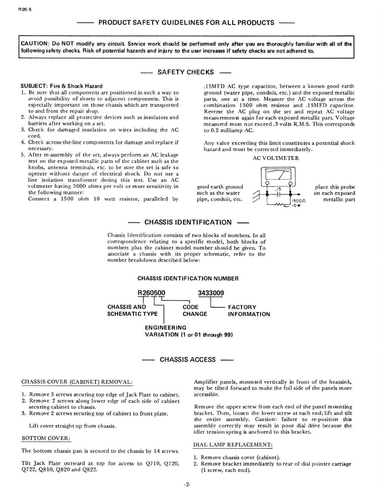
Connecta 1500ohm10wattresistor,paralleledby
.15MFD
ACtypecapacitor,
between
a
known
goodearth
ground
(waterpipe,conduit,etc.)andtheexposedmetallic
parts,
oneata time.MeasuretheACvoltageacrossthe
combination1500ohmresistorand.15MFDcapacitor.
Reverse
theACplugonthesetandrepeatACvoltage
measurementsagainforeachexposedmetallic
part
Voltage
measured
mustnotexceed.3volts
R.M.S.
Thiscorresponds
to0.2milliampAC.
Anyvalueexceedingthislimitconstitutesa potentialshock
hazard
andmustbecorrectedimmediately.
AC
VOLTMETER
goodearthground
suchasthewater
pipe,
conduit,etc.
place
thisprobe
oneachexposed
metallic
part
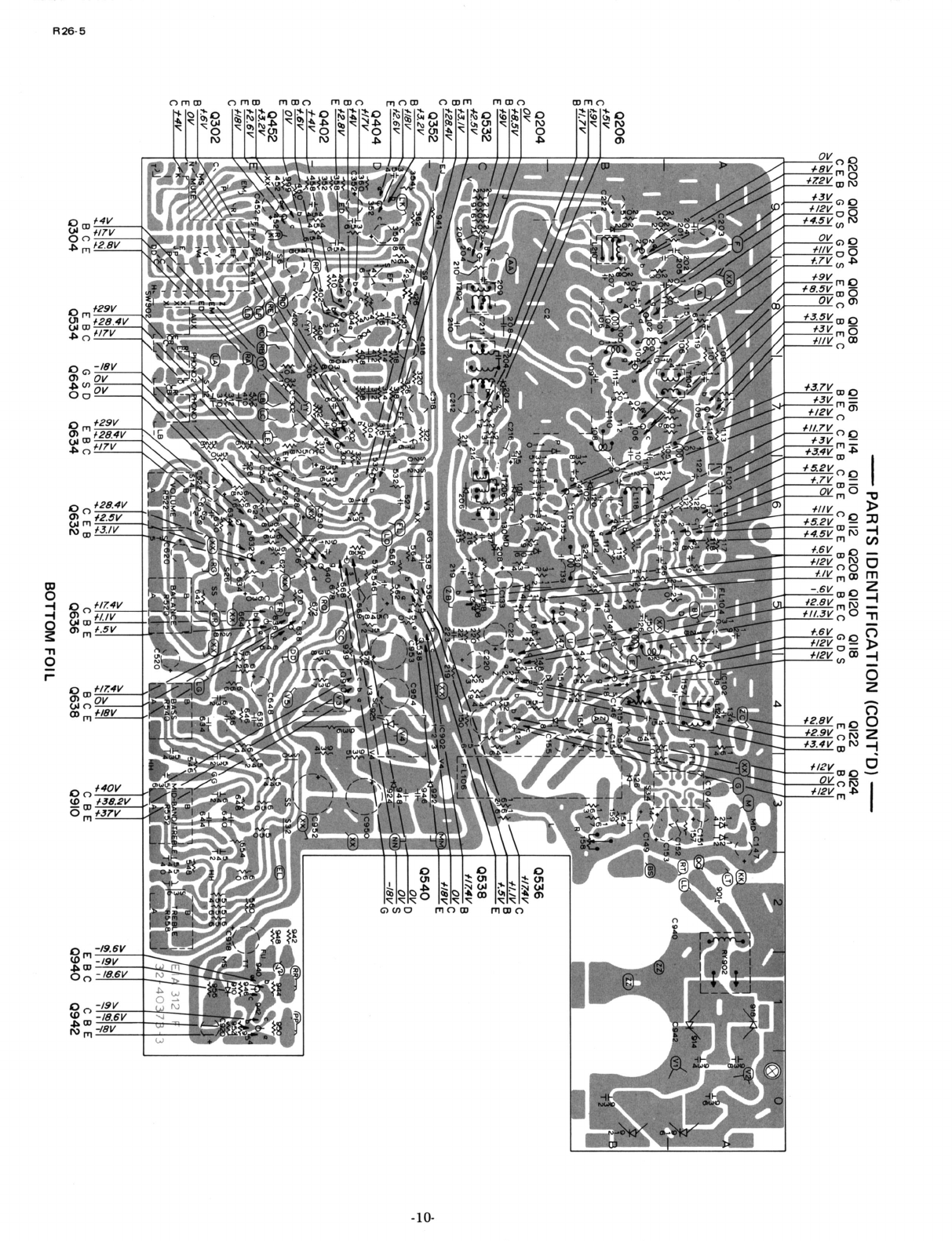
CHASSIS
IDENTIFICATION
CHASSIS
IDENTIFICATION
Chassis
Identificationconsistsoftwoblocksofnumbers.Inall
correspondencerelatingtoa specificmodel,bothblocksof
numbers
plusthecabinetmodelnumbershouldbegiven.To
associate
a chassis
with
itsproperschematic,refertothe
numberbreakdowndescribed
below:
CHASSIS
ACCESS
CHASSIS
COVER
(CABINET)
REMOVAL:
1.
Remove3 screwssecuringtopedgeof
Jack
Platetocabinet.
2.Remove2 screwsalong
lower
edgeofeachsideofcabinet
securingcabinettochassis.
3.Remove2 screwssecuringtopofcabinettofrontplate.
Lift
coverstraightupfromchassis.
BOTTOM
COVER:
The
bottomchassispanissecuredtothechassisby14screws.
Tilt
Jack
PlateoutwardattopforaccesstoQ710,Q720,
Q722,
Q810,Q820andQ822.
Amplifierpanels,mountedverticallyinfrontoftheheatsink,
maybetiltedforwardtomakethe
foil
sideofthepanelsmore
accessible.
Removetheupperscrewfromeachendofthepanelmounting
bracket.
Then,
loosen
the
lower
screwateachend;liftand
tilt
theentireassembly.Caution:failuretore-positionthis
assembly
correctlymayresultinpoordialdrivebecausethe
idlertensionspringisanchoredtothisbracket.
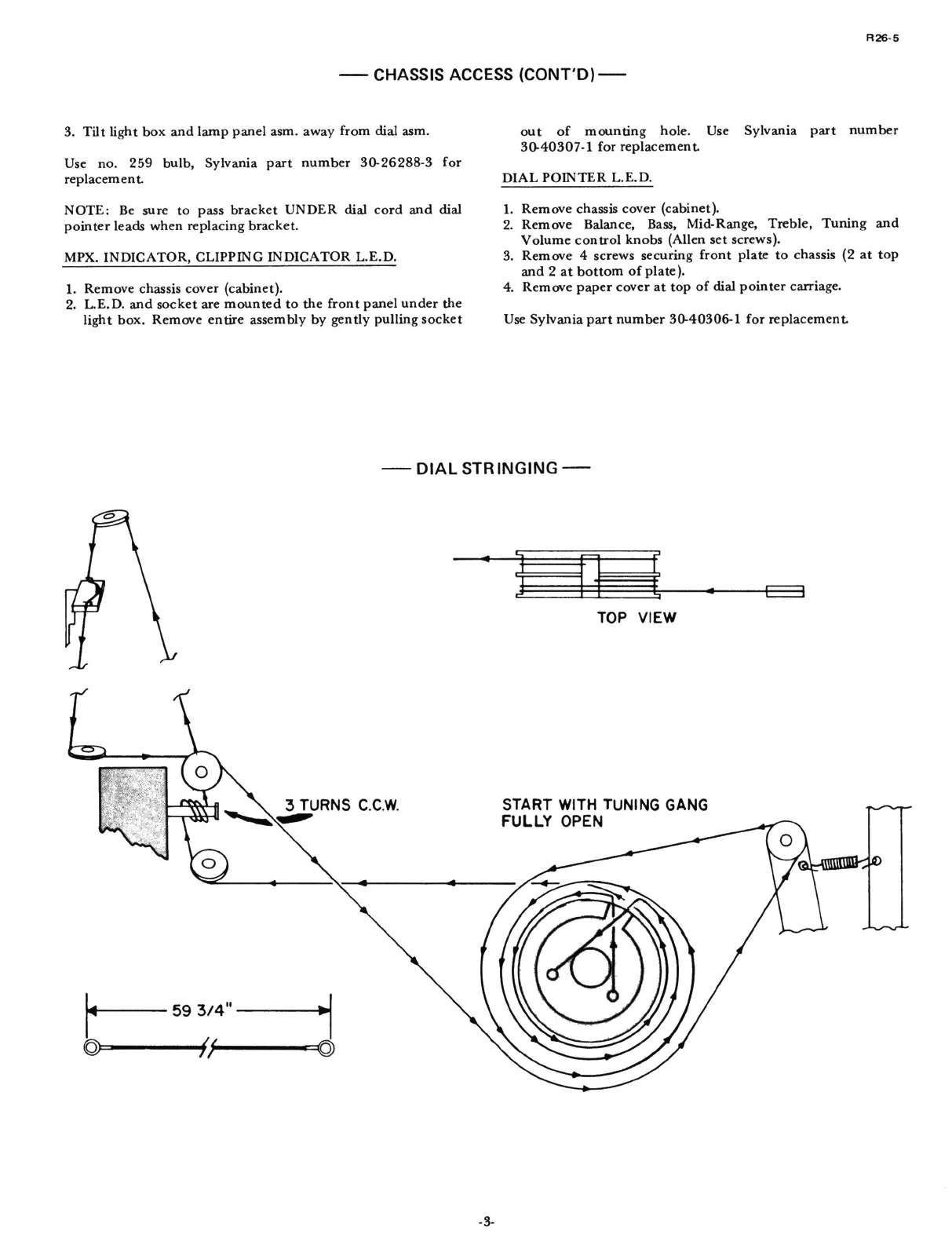
DIAL
LAMP
REPLACEMENT:
1.
Removechassiscover(cabinet).
2.Removebracketimmediatelyto
rear
ofdialpointer
carriage
(1
screw,eachend).