GUANDALINI PPK DJI PHANTOM 4 ADV User manual

MANUAL AND DOCUMENTATION
ASSEMBLY MANUAL FOR KIT PPK ON
DJI PHANTOM 4 ADV/PRO
São Paulo, 09th April, 2020
Revisão nº 3
Manual developed by Guandalini Equipamentos Topográficos Technical Team

Sumário
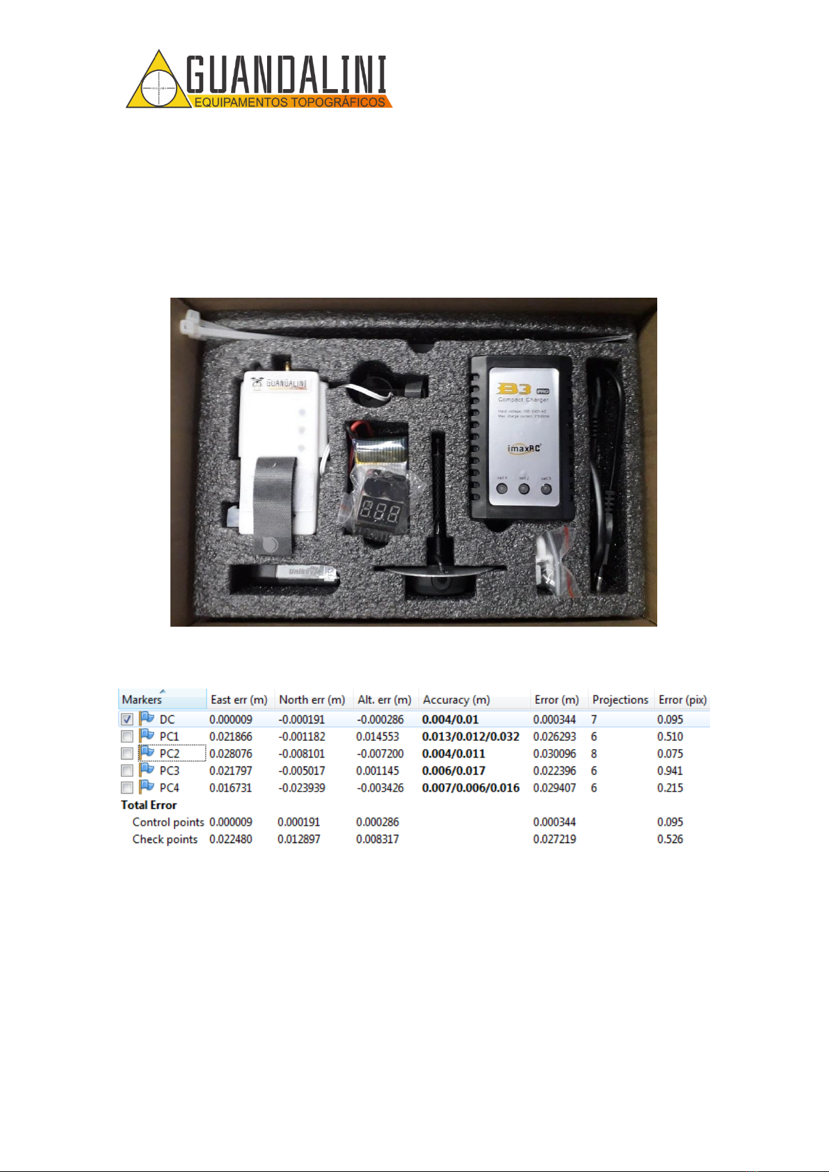
1. KIT PPK...................................................................................................................... 2
2. ASSEMBLING THE KIT PPK ON PHANTOM 4 ADV/PRO............................................. 3
2.1. DRONE MOUNTING ........................................................................................... 3
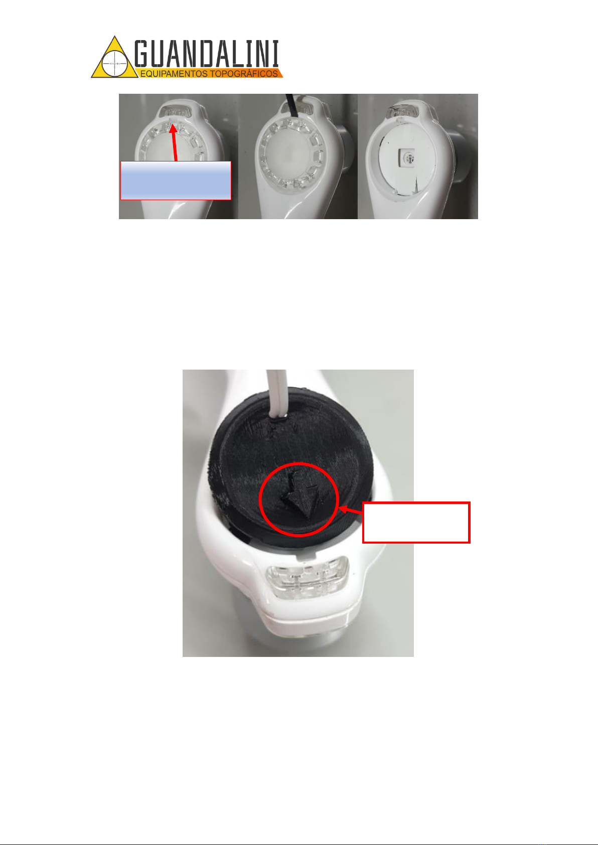
2.1.1. STEP 1 ......................................................................................................... 3
2.1.2. STEP 2 ......................................................................................................... 3
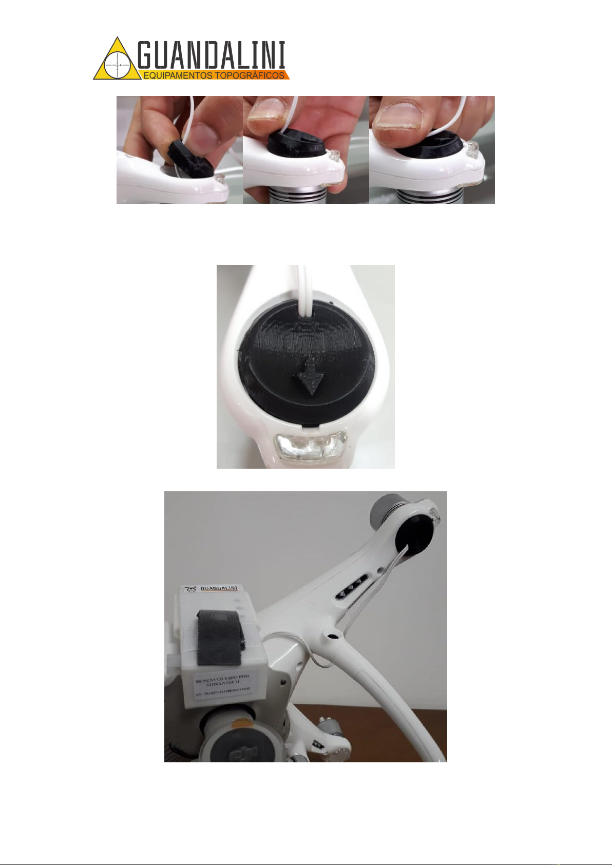
2.1.3. STEP 3 ......................................................................................................... 4
2.1.4. STEP 4 ......................................................................................................... 5
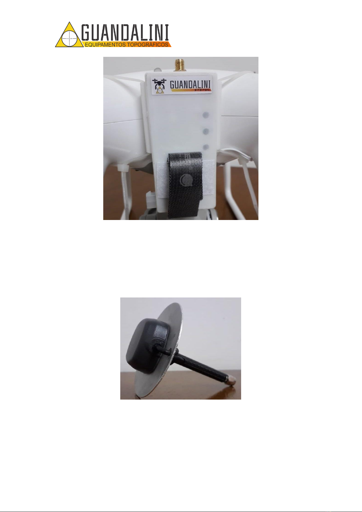
2.1.5. STEP 5 ......................................................................................................... 7
2.1.6. STEP 6 ......................................................................................................... 9
2.1.7. STEP 7 ....................................................................................................... 11
2.1.8. STEP 8 ....................................................................................................... 12
2.2. MOUNTING ON THE REMOTE CONTROL......................................................... 13
2.3. PHANTOM 4 ADV/PRO BOX CUTTING ............................................................. 14
2.4. HOW TO CHARGE BATTERY FROM THE PPK KIT .............................................. 16
2.4.1. CHARGER IMAX B3.................................................................................... 16
2.4.2. AC/DC ADAPTER CHARGER....................................................................... 18
2.5. HOW TO MEASURE THE BATTERY CHARGE OF THE PPK KIT ........................... 19
2.5.1. LIPO BATTERY METER............................................................................... 20
3. CONFIGURAÇÃO DJI GO.......................................................................................... 22
4. FLIGHT PROCEDURES.............................................................................................. 25
4.1. STARTING THE BASE......................................................................................... 25
4.2. POSITIONING THE DRONE................................................................................ 25
4.3. HOW TO CONNECT THE CONTROL MODULE................................................... 26
4.4. INITIALIZING THE SYSTEM................................................................................ 27
4.5. SHUTTING DOWN THE SYSTEM ....................................................................... 29

MANUAL DE MONTAGEM KIT PPK NO
DJI PHANTOM 4 ADV/PRO
2
Av. Paulo VI, 1952 (novo n 184) • Sumaré • CEP 01262-010 • São Paulo • SP
(11) 4800-3157 • www.guandalinibr.com
1. KIT PPK
The PPK kit is developed by the engineering team at Guandalini Equipamentos
Topograficos and can be integrated into your PHANTOM 4 ADVANCED or PRO. The kit
consists of the Reach M + card, an adapted GNSS antenna and the Guandalini PPK
software (Figure 1Figure 1).
Figure 1 - Guandalini PPK Kit
In Figure 2, observe the result of the flight with a height of 80m.
Figure 2 - Mean error obtained
Mean error: 2,7cm

MANUAL DE MONTAGEM KIT PPK NO
DJI PHANTOM 4 ADV/PRO
3
Av. Paulo VI, 1952 (novo n 184) • Sumaré • CEP 01262-010 • São Paulo • SP
(11) 4800-3157 • www.guandalinibr.com
2. ASSEMBLING THE KIT PPK ON PHANTOM 4 ADV/PRO
2.1. DRONE MOUNTING
2.1.1. STEP 1
With the KIT PPK GUANDALINI in hands, remove the control module from the foam
cradle, shown in Figure 3.
Figure 3 - Control Module Guandalini PPK
2.1.2. STEP 2
Remove the velcro that is attached to the control module (Figure 4), peel off the
protective layer of glue from it and place it in the center of the front position of the
Phantom 4 ADV / PRO, that is, on the face where the camera faces you, as shown in
Figure 5.
Figure 4 - Removal of the velcro that is glued to the Phantom 4 ADV/PRO.

MANUAL DE MONTAGEM KIT PPK NO
DJI PHANTOM 4 ADV/PRO
4
Av. Paulo VI, 1952 (novo n 184) • Sumaré • CEP 01262-010 • São Paulo • SP
(11) 4800-3157 • www.guandalinibr.com
Figure 5 - Positioning the Velcro on the Phantom 4 ADV/PRO.
2.1.3. STEP 3
Remove the protective cover from the original LED on the right front side (looking in
front of the drone –Figure 6) with a small screwdriver, using a small opening in the
protector (Figure 7).
Figure 6 - Indication for removing the Phantom 4 ADV/PRO LED protector..

MANUAL DE MONTAGEM KIT PPK NO
DJI PHANTOM 4 ADV/PRO
5
Av. Paulo VI, 1952 (novo n 184) • Sumaré • CEP 01262-010 • São Paulo • SP
(11) 4800-3157 • www.guandalinibr.com
Figure 7 - Indication of the opening in the led protector. B) Screwdriver for removing the Phantom 4
ADV/PRO protector. C) Protector removed
2.1.4. STEP 4
Pass the cable behind the leg and insert the new LED protector in the space for it,
directing the arrow out of the drone (Figure 8), in Figure 9 the sequence for placing the
new protector is shown.
Figure 8 - Positioning of the LED protector for PHANTOM 4 ADV/PRO.
OPENING IN THE
LED PROTECTOR.
ATTENTION TO
THE DIRECTION
OF THE ARROW
A
B
C

MANUAL DE MONTAGEM KIT PPK NO
DJI PHANTOM 4 ADV/PRO
6
Av. Paulo VI, 1952 (novo n 184) • Sumaré • CEP 01262-010 • São Paulo • SP
(11) 4800-3157 • www.guandalinibr.com
Figure 9 - A) Position to place the protector. B) Where to press the new protector. C) How it should look.
Figure 10 and Figure 11 show what the protector should look like on the Phantom 4
ADV/PRO after installation.
Figure 10 - Installation of the LED protector completed..
Figure 11 - Partial assembly of the GUANDALINI PPK KIT for Phantom 4 ADV/PRO.
A
B
C

MANUAL DE MONTAGEM KIT PPK NO
DJI PHANTOM 4 ADV/PRO
7
Av. Paulo VI, 1952 (novo n 184) • Sumaré • CEP 01262-010 • São Paulo • SP
(11) 4800-3157 • www.guandalinibr.com
2.1.5. STEP 5
Position the control module in the center of the drone, aligning the marking that exists
on the control module with the line of the central axis of the drone, as shown in Figure
12 and Figure 13. Soon after, 1 nylon clamp should be inserted (Figure 14) in each arm
of the control module (Figure 15) and wrap it around the drone arm. When wrapping,
be sure to tighten the tapes together so that the control module is in the center, as
shown in Figure 16.
Attention!
Tighten the nylon clamp just enough so that the kit does not move. If too tight, it can break.
Figure 12 - Marking for alignment of the control module with the drone.
Figure 13 - Correct positioning of the control module in relation to the drone.

MANUAL DE MONTAGEM KIT PPK NO
DJI PHANTOM 4 ADV/PRO
8
Av. Paulo VI, 1952 (novo n 184) • Sumaré • CEP 01262-010 • São Paulo • SP
(11) 4800-3157 • www.guandalinibr.com
Figure 14 - Nylon clamp.
Figure 15 - Insertion of the nylon tape on the arm of the control module.

MANUAL DE MONTAGEM KIT PPK NO
DJI PHANTOM 4 ADV/PRO
9
Av. Paulo VI, 1952 (novo n 184) • Sumaré • CEP 01262-010 • São Paulo • SP
(11) 4800-3157 • www.guandalinibr.com
Figure 16 - Nylon tapes installed.
2.1.6. STEP 6
Remove the antenna (Figure 17) from the foam cradle and screw it onto the connector
found on the control module (Figure 18). Make sure the antenna is secure and
connected as shown in Figure 19.
Figure 17 - Antenna Tallysman.

MANUAL DE MONTAGEM KIT PPK NO
DJI PHANTOM 4 ADV/PRO
10
Av. Paulo VI, 1952 (novo n 184) • Sumaré • CEP 01262-010 • São Paulo • SP
(11) 4800-3157 • www.guandalinibr.com
Figure 18 - Control module connector..
Figure 19 - Antenna positioned on the control module.

MANUAL DE MONTAGEM KIT PPK NO
DJI PHANTOM 4 ADV/PRO
11
Av. Paulo VI, 1952 (novo n 184) • Sumaré • CEP 01262-010 • São Paulo • SP
(11) 4800-3157 • www.guandalinibr.com
2.1.7. STEP 7
Remove the battery (Figure 20) from the foam cradle and place it on the control
module with the cables facing down. Make sure to tie the velcro tape to the
battery and leave the 3-wire connector attached to the tape as well, as shown in
Figure 21.
Figure 20 - Battery used to power the control module.
Figure 21 - A) Place to put the battery. B) Proper allocation of the battery in the control module.
A
B

MANUAL DE MONTAGEM KIT PPK NO
DJI PHANTOM 4 ADV/PRO
12
Av. Paulo VI, 1952 (novo n 184) • Sumaré • CEP 01262-010 • São Paulo • SP
(11) 4800-3157 • www.guandalinibr.com
2.1.8. STEP 8
Connect the battery to the control module, as shown in Figure 22. Both
connectors have a marking that indicates the positive side and when fitted, you
should feel a click. The Figure 23 shows how the equipment should look with the
battery inserted, so it will be ready to fly!
Figure 22 - Connecting the battery to the control module.
Figure 23 - Flight Ready Equipment.

MANUAL DE MONTAGEM KIT PPK NO
DJI PHANTOM 4 ADV/PRO
13
Av. Paulo VI, 1952 (novo n 184) • Sumaré • CEP 01262-010 • São Paulo • SP
(11) 4800-3157 • www.guandalinibr.com
2.2. MOUNTING ON THE REMOTE CONTROL
So that it is not necessary to use a screwdriver in the field to remove the tablet support
(Figure 24), the KIT PPK GUANDALINI comes with a plastic lock and a screw (Figure 25)
to be installed in the control.
Figure 24 - Slit screw on the tablet support.
Figure 25 - Plastic lock and screw included with the kit.
To install, remove the original central screw positioned on the tablet support (Figure 24)
and install the screw that comes with the kit, as shown in Figure 26. You will notice that
the support now rotates to the left. After this step, insert the lock on the bottom of the
support (Figure 28) and the installation is finished (Figure 29). In this way, to remove the
support from the tablet, simply remove the lock and unscrew the support without the
need for tools.

MANUAL DE MONTAGEM KIT PPK NO
DJI PHANTOM 4 ADV/PRO
14
Av. Paulo VI, 1952 (novo n 184) • Sumaré • CEP 01262-010 • São Paulo • SP
(11) 4800-3157 • www.guandalinibr.com
Figure 26 - Screw inserted in the tablet support.
2.3. PHANTOM 4 ADV/PRO BOX CUTTING
To accommodate the PPK GUANDALINI KIT in the original DJI case with remote control,
it is necessary to cut out two areas of the Styrofoam case as shown in Figure 27.

MANUAL DE MONTAGEM KIT PPK NO
DJI PHANTOM 4 ADV/PRO
15
Av. Paulo VI, 1952 (novo n 184) • Sumaré • CEP 01262-010 • São Paulo • SP
(11) 4800-3157 • www.guandalinibr.com
Figure 27 - A) Area to be cut in the case. B) Cut-out case.
It is also necessary to store the controller without the tablet support (as shown in Figure
27).
Figure 28 - Inserting the lock.

MANUAL DE MONTAGEM KIT PPK NO
DJI PHANTOM 4 ADV/PRO
16
Av. Paulo VI, 1952 (novo n 184) • Sumaré • CEP 01262-010 • São Paulo • SP
(11) 4800-3157 • www.guandalinibr.com
Figure 29 - Positioning the tablet support lock.
2.4. HOW TO CHARGE BATTERY FROM THE PPK KIT
2.4.1. CHARGER IMAX B3
For battery recharge, a charger is included (Figure 30).
Figure 30 - Charger included with the PPK Kit.
ATTENTION!!!
The charger should only be connected to the power plug if the battery is connected.

MANUAL DE MONTAGEM KIT PPK NO
DJI PHANTOM 4 ADV/PRO
17
Av. Paulo VI, 1952 (novo n 184) • Sumaré • CEP 01262-010 • São Paulo • SP
(11) 4800-3157 • www.guandalinibr.com
The recharge procedure is:
1. Connect the battery to the charger (Figure 31)
2. Connect the charger to the power plug
Figure 31 - Connecting the battery to the charger.
When connecting the battery to the charger, the ‘cell 1’ and ‘cell 2’ lights will light red
and the ‘cell 3’ light will light green (Figure 32).
Figure 32 - Battery being recharged.
When charging is complete, all lights will turn green.
After full recharge the battery lasts for 3h 58min. As it is a LiPo battery, full discharge is
not recommended, as it may stop working. So it is recommended that it be used only

MANUAL DE MONTAGEM KIT PPK NO
DJI PHANTOM 4 ADV/PRO
18
Av. Paulo VI, 1952 (novo n 184) • Sumaré • CEP 01262-010 • São Paulo • SP
(11) 4800-3157 • www.guandalinibr.com
for 3h 30min. After that, recharge it. Remembering that the voltage in each cell must
not be less than 3V.
2.4.2. AC/DC ADAPTER CHARGER
The new kits PPK are shipped with this battery charger (Figura 33Figura 33).
Figura 33 - AC/DC adapter charger.
This charger has a status LED. When the battery is being charged, the LED lights red
(Figure 34); when charging is complete, it switches to green (Figure 35).
Figure 34 - Battery being charged.

MANUAL DE MONTAGEM KIT PPK NO
DJI PHANTOM 4 ADV/PRO
19
Av. Paulo VI, 1952 (novo n 184) • Sumaré • CEP 01262-010 • São Paulo • SP
(11) 4800-3157 • www.guandalinibr.com
Figure 35 - Completed charge.
2.5. HOW TO MEASURE THE BATTERY CHARGE OF THE PPK
KIT
Figure 36 - Battery life graph and LED colors.
The battery level is indicated by the color of the LED located above the control module.
After initialization (5 minutes), the LED flashes every 30 seconds and its color represents
the battery charge (Figure 36).
GREEN: 100 80%
CYAN 80-50%
This manual suits for next models
1
Table of contents
Other GUANDALINI Quadcopter manuals