manuals.online logo
Brands
  1. Home
  2. •
  3. Brands
  4. •
  5. Gulf Coast Fans
  6. •
  7. Fan
  8. •
  9. Gulf Coast Fans Ramsey User manual

Gulf Coast Fans Ramsey User manual

Ramsey
Thank you for purchasing a Gulf Coast Fans Inc. product. It will provide years of cost
efficient comfort. With over a decade of experience in ensuring quality workmanship
at an affordable price, we stand behind our product and we hope you will too.
IMPORTANT PRECAUTIONS
Read these instructions carefully before you start.
Turn off the power at the source before installation, servicing, or cleaning.
WARNING--TO REDUCE THE RISK OF FIRE OR ELECTRIC SHOCK, DO NOT USE
THIS FAN WITH ANY SOLID STATE SPEED CONTROL DEVICE. USE ONLY GULF
COAST CONTROLS.
WARNING--TO REDUCE THE RISK OF PERSONAL INJURY, DO NOT BEND THE
BLADE IRONS WHEN INSTALLING ON BLADES, BALANCING THE BLADES, OR
CLEANING THE FAN. DO NOT INSERT FOREIGN OBJECTS IN BETWEEN
ROTATING FAN BLADES.
WARNING--TO REDUCE THE RISK OF FIRE, ELECTRIC SHOCK, OR PERSONAL
INJURY, MOUNT FAN TO AN OUTLET BOX MARKED "ACCEPTABLE FOR FAN
SUPPORT" AND USE THE MOUNTING SCREWS PROVIDED WITH THE OUTLET
BOX.
If you don't feel comfortable hanging and wiring this fan, we recommend that you hire a
qualified electrician to install it.
All wiring and electrical connections must meet the National Electrical Code and any
local codes that may apply.
After installation, fan blades must be at least seven (7) feet from the floor.
1
2
3
4
5
6
7
8
READ AND SAVE THESE INSTRUCTIONS
Page 1
Gulf Coast Fans 2010 - Portions â1993
2 - Wood Screws
2 - Star Washers
2 - Flat Washers
1 - Halogen Bulb
3 - Wirenuts
21 - Blade Screws
21 - Metal Washers
21 - Rubber Washers
Screw Package
To begin with, the site of installation must be clear of any obstructions. Walls, cabinet or cupboard
doors, and AC/heating vents (strong air currents will cause fan to wobble ) are common obstructions.
Also, you will need a securely mounted outlet box that is listed for fan support.
The only tools you will need are : A medium Phillips screwdriver, common sense, and a little caution.
Remove all parts from plastic bags, including the screw package.
B.
A.
A. Attach the blades to the blade arms using the blade screws, metal washers
and rubber washers, four of each per blade, as shown in Fig 1.
CANOPYCANOPY
GLOBEGLOBE
BALL &
DOWNROD
BALL &
DOWNROD
5 BLADE ARMS5 BLADE ARMS
TOP SLEEVETOP SLEEVE
CLEVIS PINCLEVIS PIN
SAFETY CLIP
& WASHER
SAFETY CLIP
& WASHER
Remove all of the parts from the top styrofoam and remove the styrofoam. Use
this top piece to support the fan during preliminary assembly.
I. Inventory the parts
II. Preliminary Assembly.
5 BLADES5 BLADES
FIG. 1
Take the ball & downrod and loosen the set
screw in the ball. Remove the pin and the ball
from the downrod. (If you have a longer
downrod, use it now.) See Fig. 2
Loosen the couplers set screws. Feed the
three wires from the top of the fan through the
downrod and insert the downrod into the
coupler. Align the holes in the downrod with
the holes in the coupler. Insert the clevis pin
through the coupler and the washer. Insert the
safety clip in to the hole in the clevis pin.
Tighten the set screws. See Fig. 3
Place the top sleeve, then the canopy around the
downrod. Slide the ball onto the downrod and
replace pin. See Fig. 4 Slide the top sleeve down
over the coupler.
Raise the ball so that the pin is in the slot and
tighten the set screw. See Fig. 5
B.
2.
1.
3.
4.
5. Make sure all of the screws are tight. At this time you may want to shorten the wires
from the fan to 6" from the ball. This helps when you tuck the wires into outlet box.
Fig. 5
Fig. 2
Ball Set Screw
Pin
Fig. 3
Fig. 4
Page 2
HANGING BRACKET
w/2 CANOPY SCREWS
HANGING BRACKET
w/2 CANOPY SCREWS
Gulf Coast Fans 2010 - Portions â1993
II. Preliminary Assembly continued from page 2.
C.1.Take the hanging bracket and secure it to the outlet box (marked 'Acceptable For Fan Support')
using the mounting screws provided with the outlet box. Tighten them evenly. If you are mounting
the fan directly to the building structure, use the wood screws provided, and secure to a joist.
WARNING - To Reduce The Risk Of Fire, Electric Shock, Or Personal
Injury Mount Fan To An Outlet Box Marked "Acceptable For Fan
Support" And Use The Mounting Screws Provided With The Outlet Box.
2.
III. Now to hang the fan...
Holding the fan carefully, lift it up to hanging bracket. Place the ball into cradle
of the bracket. Turn the entire motor assembly until it locks into place. The tab
on the bracket must be in the groove in the ball. Make sure the wires are not
being pinched.
Fig. 7
This fan can be operated by a wall control or remote
control unit. The basic wiring instructions below are for a
wall control. Please refer to the instructions provided with
the wall control. For use with a remote control refer to the
wiring instructions provided with the remote control. Keep
in mind, the supply wire colors may vary. (The wire colors
in parentheses are commonly found in existing structures.)
Use the large orange wirenuts to make the connections.
Please be sure power supply is off!
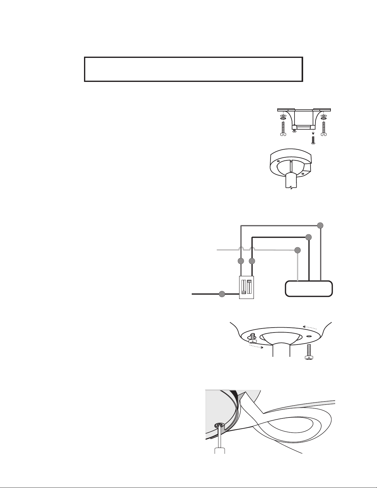
IV. Wiring instructions.
1. Green ground wires to outlet box ground. (bare)
2. Black wire from fan to (black) wire from fan control.
3. Blue wire from fan to (red) wire from light control.
4. White wire from fan to neutral supply. (white)
Fig. 8
BLUE
FAN
BLK
WHT
FROM FAN CONTROL
FROM LIGHT CONTROL
SUPPLY NEUTRAL
SUPPLY HOT
FAN LIGHT
GULF COAST
Now tuck the wires and wirenuts carefully into outlet box.
Make sure wirenuts remain tightly on connections.
Page 3
V. Final Assembly
A.
B.To avoid scratching the switch cup or damaging the motor, do not run the fan without
the blades. So, the next step is to mount the blade assemblies on the motor.
Fig. 10
Slide the base of the blade arm beneath the halogen
fitter where there is the large cutout. See Fig. 10.
Line up one hole in the blade arm base with with an
appropriate hole on the motor. Insert a motor screw
and tighten. Rotate the motor so that the other hole on
the blade arm base is visible through the cutout.
Insert another motor screw into the other hole and
tighten. Repeat this with the rest of the blade
assemblies, and then retighten all of the screws.
Remove one canopy screw (also Fig 7) and loosen the other. Make
sure all of the wires are accessible and are not being pinched. Also,
make sure the bracket doesn't wobble. Fig. 6
With the motor in place and the wires out of the way, slide the
canopy up to the hanging bracket. The canopy screw in the bracket
will come through the large end of the key slot in the canopy. Fig. 9.
Turn the canopy slightly, counter-clockwise, to hold in place, and
insert remaining canopy screw. Tighten the screws.
FIG. 9
CANOPY
Gulf Coast Fans 2010 - Portions â1993
The speeds are controlled using the wall control or remote control.
To reverse the airflow, turn off fan and let blades come to a
complete stop. The reverse switch is located on top of the motor,
recessed within one of the oval holes; slide it to the other side.
VI. Turn the power supply back on and prepare to be comfortable!
V. Final Assembly continued from Page 3
TroubleshootingVII.
Fan won't run - Check power supply.
Reverse switch is not fully engaged one way.
Check wirenut connections at fan and switch.
Double check wiring diagrams.
Fan makes noise -
Please allow 24 hrs to fully seat bearings
Screw(s) is(are) loose somewhere.
Ball is not seated properly in hanging bracket.
Variable control (solid-state dimmer) in the circuit.
Fan wobbles - Bracket is loose at the ceiling.
Loose screw at top of fan.
Ball is not seated properly in hanging bracket.
Complete Assembly Breakdown - Fig. 13
Our service department is
always ready to help.
We stand behind our product
and always strive to satisfy our
customer.
Gulf Coast Fans, Inc.
P.O. Box 10,000
Oldsmar Florida
34677-0106
Page 4
To install the halogen bulb, use the paper sleeve to install it into
the bracket. Press one end of the bulb into one of the sockets
until other end can be inserted into other socket. Halogen bulbs
must never be touched with bare skin. The oils cause the bulb to
crack and fail. If the bulb is touched, clean it off thoroughly with
isopropyl achohol and a cotton swab or lint-free cloth. Reinstall.
Install the glass globe and you're done! There are three tabs
on the halogen fitter. There are corresponding grooves along
the lip of the globe. See Fig 12. With the globe firmly in two
hands, line up the nearest indentation with an opening to the
groove on the globe. Lift the glass into place and turn it
C.
D. Fig. 12 TAB
GROOVE
DO NOT TOUCH
HALOGEN BULB
Fig. 11
Gulf Coast Fans 2010 - Portions â1993

This manual suits for next models

2

Other Gulf Coast Fans Fan manuals

Gulf Coast Fans Luna User manual

Gulf Coast Fans

Gulf Coast Fans Luna User manual

Gulf Coast Fans HC-1131 User manual

Gulf Coast Fans

Gulf Coast Fans HC-1131 User manual

Gulf Coast Fans Twin Star III User manual

Gulf Coast Fans

Gulf Coast Fans Twin Star III User manual

Gulf Coast Fans Futura HC-1992-DA User manual

Gulf Coast Fans

Gulf Coast Fans Futura HC-1992-DA User manual

Gulf Coast Fans Hercules - 96SGD User manual

Gulf Coast Fans

Gulf Coast Fans Hercules - 96SGD User manual

Gulf Coast Fans 4YU26 User manual

Gulf Coast Fans

Gulf Coast Fans 4YU26 User manual

Popular Fan manuals by other brands

Panasonic K14Y2 Operating and installation instructions

Panasonic

Panasonic K14Y2 Operating and installation instructions

Daikin DP14UM Service instructions

Daikin

Daikin DP14UM Service instructions

Jaga OXYGEN Technical manual

Jaga

Jaga OXYGEN Technical manual

Lindab Premum Series installation instructions

Lindab

Lindab Premum Series installation instructions

Plymovent TEV Installation and user manual

Plymovent

Plymovent TEV Installation and user manual

Accurex XRUD-060 Installation, operation and maintenance manual

Accurex

Accurex XRUD-060 Installation, operation and maintenance manual

BRAYER BR4955 instruction manual

BRAYER

BRAYER BR4955 instruction manual

Fanaway CORBELLE instructions

Fanaway

Fanaway CORBELLE instructions

TaoTronics TT-TF009 user manual

TaoTronics

TaoTronics TT-TF009 user manual

Broan HFL695 user manual

Broan

Broan HFL695 user manual

Beko EFT4100W user manual

Beko

Beko EFT4100W user manual

Steba VT S6 Instructions for use

Steba

Steba VT S6 Instructions for use

Lasko T48310 Important instructions & operating manual

Lasko

Lasko T48310 Important instructions & operating manual

Faro Barcelona Jaca 33175 manual

Faro Barcelona

Faro Barcelona Jaca 33175 manual

Skil 3163 Original instructions

Skil

Skil 3163 Original instructions

Ruck Ventilatoren EMIX Assembly instruction

Ruck Ventilatoren

Ruck Ventilatoren EMIX Assembly instruction

Home Decorators Collection DANIEL 52179 Use and care guide

Home Decorators Collection

Home Decorators Collection DANIEL 52179 Use and care guide

Zehnder Rittling ComfoAir 350 Luxe user manual

Zehnder Rittling

Zehnder Rittling ComfoAir 350 Luxe user manual

manuals.online logo
manuals.online logoBrands
  • About & Mission
  • Contact us
  • Privacy Policy
  • Terms and Conditions

Copyright 2025 Manuals.Online. All Rights Reserved.