Gulf Coast Fans Futura HC-1992-DA User manual

Futura HC-1992-DA
READ AND SAVE THESE INSTRUCTIONS
Thank you for purchasing a Gulf Coast Fans Inc. product. It will provide
years of cost efficient comfort. With over a decade of experience in ensuring
quality workmanship at an affordable price, we stand behind our product and
we hope you will too.
IMPORTANT PRECAUTIONS
Read these instructions carefully before you start.
Turn off the power at the source before installation, servicing, or cleaning.
WARNING--TO REDUCE THE RISK OF FIRE OR ELECTRIC SHOCK, DO NOT USE THIS
FAN WITH ANY SOLID STATE SPEED CONTROL DEVICE. USE ONLY GULF COAST
CONTROLS.
WARNING--TO REDUCE THE RISK OF PERSONAL INJURY, DO NOT BEND THE
BLADE IRONS WHEN INSTALLING ON BLADES, BALANCING THE BLADES, OR
CLEANING THE FAN. DO NOT INSERT FOREIGN OBJECTS IN BETWEEN ROTATING
FAN BLADES.
WARNING--TO REDUCE THE RISK OF FIRE, ELECTRIC SHOCK, OR PERSONAL
INJURY, MOUNT FAN TO AN OUTLET BOX MARKED "ACCEPTABLE FOR FAN
SUPPORT" AND USE THE MOUNTING SCREWS PROVIDED WITH THE OUTLET BOX.
If you don't feel comfortable hanging and wiring this fan, we recommend that you hire a
qualified electrician to install it.
All wiring and electrical connections must meet the National Electrical Code and any local
codes that may apply.
After installation, fan blades must be at least seven (7) feet from the floor.
1
2
3
4
5
6
7
8
Page 1
Gulf Coast Fans 2010 - Portions â1993

To begin with, the site of installation must be clear of any obstructions. Walls, cabinet or cupboard doors,
and AC/heating vents (strong air currents will cause fan to wobble ) are common obstructions.
Also, you will need a securely mounted outlet box that is listed for fan support. You may also mount fan
directly to a ceiling joist, but you must use a Ceiling Fan Swag Kit to provide power.
The only tools you will need are : A medium Phillips screwdriver, common sense, and a little caution.
Remove all parts from plastic bags,
including the screw package.
A.
CANOPYCANOPY
SWITCH
CUP
SWITCH
CUP
BLADE
MEDALLIONS
BLADE
MEDALLIONS
BLADE
IRONS
BLADE
IRONS
BALL &
DOWNROD
BALL &
DOWNROD
Inventory the parts. Remove all of the parts from the top styrofoam and
remove the styrofoam. Use this top piece to support the fan during
preliminary assembly.
I.
Page 2
or
2- 3/16"-12x2" Wood Screws
2- 3/8" Star Washers
2- 1/2" Flat Washers
21- 3/16"-32x7/16" Blade Screws
3- Wirenuts
11- Motor Screws
1- Pull Chain Knob
Screw Package
HANGING BRACKET
w/2 CANOPY SCREWS
HANGING BRACKET
w/2 CANOPY SCREWS
Snap together blade and blade iron. Note the side of the blade you
want to show. Using the 3/16"-32x3/8" blade screws, four of each
per blade, secure blade to blade iron. Repeat this procedure with
the rest of the blades. You will have at least one screw left over, this
is a spare. Be sure all of the screws are tight. Fig. 7
B.
Fig. 7
Gulf Coast Fans 2010 - Portions â1993
Remove and discard the three (to five) black
shipping blocks from the face of the motor.
See Fig 1
B. Remove the three screws from the switch cup
plate on motor assembly. See Fig. 1.
C.
Place the motor, switch cup plate
down, in top styrofoam. Remove
the 1/4"-20x1 3/16" threaded pin
from coupler and loosen set
screw(s). See Fig. 2
D.
SWITCH CUP
SCREWS
SHIPPING
BLOCKS
SWITCH CUP
PLATE
MOTOR
FACE
FIG. 1.
FIG. 2
THREADED
PIN
SET
SCREW(S)
Take the ball & downrod and loosen the set
screw in the ball. Remove the pin and the ball
from the downrod. (If you have a longer
downrod, use it now.) See Fig. 3
Feed the three wires from the top of the fan through
the downrod and thread the downrod into the coupler.
Align the holes in the downrod with the holes in the
coupler. See Fig. 4
Insert the threaded pin and tighten it and the set screw(s).
Place the canopy around the downrod. Slide the ball onto the downrod and replace pin. See Fig. 5
Raise the ball so that the pin is in the slot and tighten the
set screw. See Fig. 6
A.1.
2.
3.
4.
5.
6. Make sure all of the screws are tight. At this time you may
want to shorten the wires from the fan to 6" from the ball.
This helps when you tuck the wires into outlet box.
FIG. 6
FIG. 4
II. Preliminary Assembly.
FIG. 3
SET
SCREW
PIN
FIG. 5

C.1.Take the hanging bracket and secure it to the outlet box (marked Acceptable For Fan Support) using
the mounting screws provided with the outlet box, Fig 8. Tighten them evenly.
WARNING - To Reduce The Risk Of Fire, Electric Shock, Or Personal
Injury Mount Fan To An Outlet Box Marked "Acceptable For Fan
Support" And Use The Mounting Screws Provided With The Outlet Box.
2.
Page 3
Remove one canopy screw (also Fig 8) and loosen the other. Make
sure all of the wires are accessible and are not being pinched. Also,
make sure the bracket doesn't wobble.
Fig. 8
II. Preliminary Assembly.
cont.
III. Hanging the fan motor
Holding the fan carefully, lift it up to hanging bracket. Place the ball into
cradle of the bracket. Turn the entire motor assembly until it locks into place.
The tab on the bracket must be in the groove in the ball. Make sure the wires
are not being pinched.
If you have a Gulf Coast Remote Control, fan should be wired according to method A.
Method B can be used with two separate controls for the fan and light, or with a combination wall control,
such as a 423L Gulf Coast control.
Now tuck the wires and wirenuts carefully into outlet box. Make sure the Green and White wires are tucked
into one side of the box and the Black and Blue wires are tucked into the other side of the box. Make sure
wirenuts remain tightly on connections.
Fig. 9
There are three common wiring methods; choose the one best suited to your needs. Keep in mind, the
supply wire colors may vary. (The wire colors in parentheses are commonly found in existing structures.)
Use the large orange wirenuts to make the connections. It is a good idea to wire the blue light kit wire
now, even if you don't have a light kit. It may save you some trouble in the future.
IV. Wiring methods and instructions.
A.
Pull chain operation only.
1. Green ground wires to outlet box ground (bare)
2. Black and blue wires from fan to hot supply (black)
3. White wire from fan to neutral supply (white)
See Fig 10.
B.
Wall control for both fan and light kit (Read the
instructions for the wall control first.)
1. Green ground wires to outlet box ground. (bare)
2. Black wire from fan to (black) wire from fan control.
3. Blue wire from fan to (red) wire from light control.
4. White wire from fan to neutral supply. (white)
See Fig 11.
C.
Pull chain operation of fan - Wall control for the light.
1. Green ground wires to outlet box ground. (bare)
2. Black wire from fan to hot supply. (black)
3. Blue wire from fan to (red) wire from wall control.
4. White wire from fan to neutral supply. (white)
See Fig 12.
FIG. 10
BLUE
FAN
BLK
WHT
SUPPLY HOT
SUPPLY NEUTRAL
FIG. 11 BLUE
FAN
BLK
WHT
FROM FAN CONTROL
FROM LIGHT CONTROL
SUPPLY NEUTRAL
SUPPLY HOT
FAN LIGHT
GULFCOAST
FIG. 12
BLUE
FAN
BLK
WHT
FROM SUPPLY HOT
FROM LIGHT CONTROL
SUPPLY NEUTRAL
SUPPLY HOT
ONON
Gulf Coast Fans 2010 - Portions â1993

Complete
Assembly
Breakdown
Fig. 17
Switch Cup
Plate
Coupler
VIII. Turn the power supply back on and prepare to be comfortable.
The first pull of the chain will give you high speed. The second is medium speed, and the third is low
speed. Once again will turn it off.
With the reverse switch in the down position, the fan will provide downward air movement and positive air
flow to cool you in the hot season. In the up position, air movement is upward and will bring heat trapped
at the ceiling , down around the rooms walls, warming you in the cold season.
*CAUTION - DO NOT ATTEMPT TO REVERSE THE FAN WHILE BLADES ARE IN MOTION*
Troubleshooting
IX.
Fan won't run - Check power supply.
Reverse switch is not fully engaged.
Pin is pushed out of switch cup wire connector
Fan makes noise -
Please allow 24 hrs. running time to fully
seat bearings.
Screw(s) is(are) loose somewhere.
Ball is not seated properly in hanging bracket.
Variable speed control (dimmer) in fan circuit.
Fan wobbles - Bracket is loose on ceiling.
Loose screw at top of fan.
Ball is not seated properly in hanging bracket.
Try switching opposing blades.
Try the blade balancing kit included.
Fig. 15
INCORRECTCORRECT
We recommend that you retighten the blade
iron to blade screws and blade iron to motor
screws after fan has been up for 30 to 60 days.
Gulf Coast Fans, Inc. products are sold at
Dan's Fan City stores.
Our service department is always ready to
help. We stand behind our product and always
strive to satisfy our customer.
Gulf Coast Fans, Inc.
300 Dunbar Avenue
Oldsmar, Florida 34677
(813)-855-7384
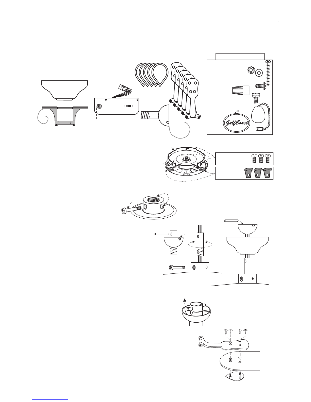
VI. To avoid scratching the switch cup or damaging the motor, do not run the fan
without the blades. So, the next step is to mount the blade assemblies on the
motor. The easiest way to do this is to insert a motor screw into one hole on the
base of the blade iron; hold it in place with a screwdriver and lift blade assembly
into place. Fig. 14. Start this screw in an appropriate hole in motor. Now insert
another into the other hole and tighten both screws. Repeat this with the rest of
the blade assemblies, and retighten all of the screws.
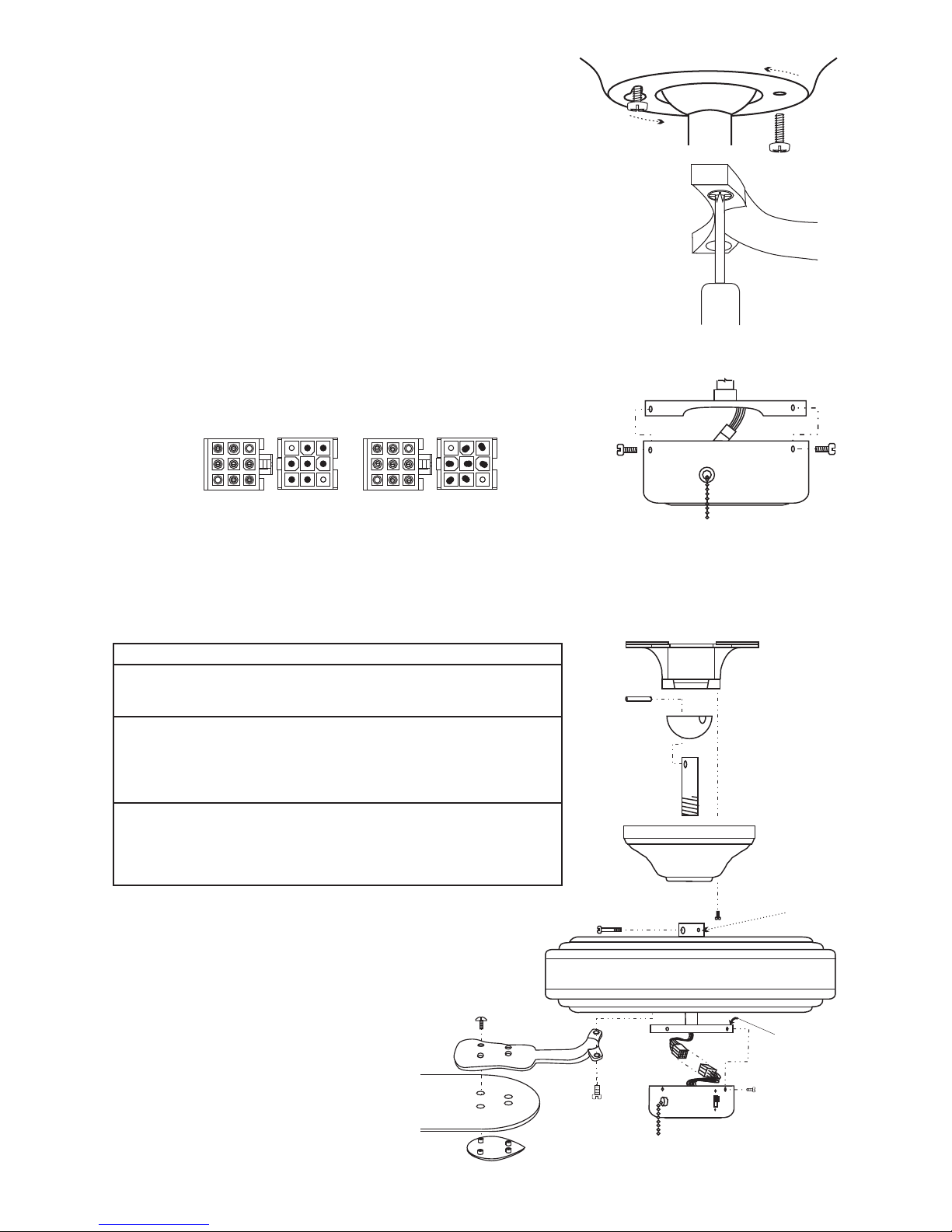
Fig. 16
V. With the motor in place and the wires out of the way, slide the
canopy up to the hanging bracket. The canopy screw in the
bracket will come through the large end of the key slot in the
canopy. Fig. 13. Turn the canopy slightly, counter-clockwise, to
hold in place, and insert remaining canopy screw. Tighten the
screws. FIG. 13
CANOPY
VII.
You're just about done now. The switch cup is the last step, and it's simple.
Notice the wire connectors in the switch cup and on the motor. They are color
coded and notched to fit only one way. Check the pins in both connectors for
alignment as shown in Fig. 15. If they the pins are only slightly misaligned,
bundle the wires tightly behind the connector when connecting. Push the
connectors together until latch secures them together and make sure none of
the pins were pushed out. Lift the cup into place . Insert one of the screws
removed earlier and thread into switch cup plate. Insert the remaining switch
cup screws and tighten all. Fig. 16.
Gulf Coast Fans 2010 - Portions â1993
FIG. 14
Table of contents
Other Gulf Coast Fans Fan manuals

Gulf Coast Fans
Gulf Coast Fans HC-1131 User manual

Gulf Coast Fans
Gulf Coast Fans Ramsey User manual

Gulf Coast Fans
Gulf Coast Fans Hercules - 96SGD User manual

Gulf Coast Fans
Gulf Coast Fans Twin Star III User manual

Gulf Coast Fans
Gulf Coast Fans 4YU26 User manual

Gulf Coast Fans
Gulf Coast Fans Luna User manual
Popular Fan manuals by other brands

TJERNLUND
TJERNLUND EF-6AUTO Owner's instructions

Matsui
Matsui MF152W instruction manual

HAMPTON BAY
HAMPTON BAY Malone Use and care guide

Terra Universal
Terra Universal RSR ECM Installation and operation manual

Sandstorm
Sandstorm S40DCF15E instruction manual

Teryair
Teryair VF Series Operation and maintenance guide