Guyson KS MK3 300 Manual

Operation &
Maintenance
Manual
Issue:
18
A6ML0260 - KS MK3 & UCR MK3 Manual
Date:
09/2016
Page: 2
Table of Contents
Manual content disclaimer ......................................................................................................................4
1. Introduction .........................................................................................................................................5
2. Safety..................................................................................................................................................6
2.1 Hazards.........................................................................................................................................6
2.2 Precautions ...................................................................................................................................6
2.3 Cleaning solutions.........................................................................................................................7
2.3.1 Type .......................................................................................................................................7
2.3.2 Use of cleaning solutions.......................................................................................................7
2.4 Safe practices ...............................................................................................................................8
2.5 Noise emission..............................................................................................................................8
2.6 Environmental ...............................................................................................................................9
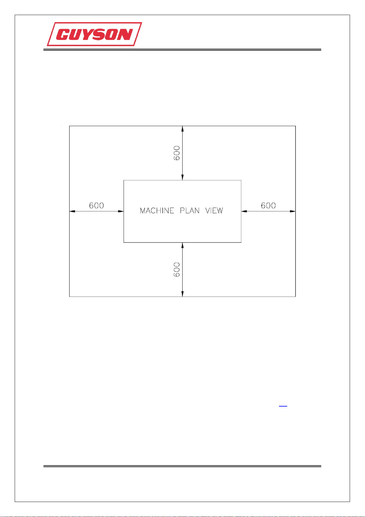
3. Installation and siting.........................................................................................................................10
3.1 Isolation and switching devices (3 phase units)..........................................................................11
3.1.1 3 phase units with flexible armoured cable..........................................................................11
3.2 Further installation for units with an external ultrasonic generator .............................................12
4. Operating instructions.......................................................................................................................13
4.1 Filling of the unit..........................................................................................................................13
4.2 Control system ............................................................................................................................14
4.2.1 Layout of the membrane panel display................................................................................14
4.2.2 LED status and fault indication ............................................................................................15
4.2.3 LCD display screens ............................................................................................................16
4.3 Start up........................................................................................................................................18
4.4 Operation ....................................................................................................................................19
4.4.1 Using baskets.......................................................................................................................19
4.4.2 Starting the ultrasonics.........................................................................................................19
4.5 Setting the heating temperature..................................................................................................20
4.6 Setting the sonics time................................................................................................................21
4.7 Shutdown ....................................................................................................................................22
4.8 Ancillary parts..............................................................................................................................22
5. Description ........................................................................................................................................23
5.1 General........................................................................................................................................23
5.2 The KS MK3 range of ultrasonic cleaning tanks.........................................................................24
5.2.1 KS MK3 range technical specification..................................................................................25
5.3 The UCR MK3 range of ultrasonic clean and rinse tanks...........................................................26
5.3.1 UCR MK3 range technical specification...............................................................................27
5.4 Optional pumping and filtration unit ............................................................................................28
5.5 Baskets........................................................................................................................................29
6. Electrical circuit and control systems................................................................................................30
6.1 Power requirements table...........................................................................................................30
6.2 Transducers ................................................................................................................................30
6.3 Thermal shock.............................................................................................................................31
6.4 Fuse replacement (on single phase units)..................................................................................32
6.5 Resetting of MCB's (on 3 phase units) .......................................................................................33
7. Cleaning solutions.............................................................................................................................34
8. Maintenance......................................................................................................................................35
8.1 Safety precautions ......................................................................................................................35
8.2 Routine preventative maintenance .............................................................................................36
8.2.1 Daily .....................................................................................................................................36
8.2.2 Weekly..................................................................................................................................37
8.2.3 Monthly.................................................................................................................................37
8.2.4 Six monthly...........................................................................................................................37
8.2.5 General.................................................................................................................................37
8.3 Draining and cleaning the plant ..................................................................................................38

Operation &
Maintenance
Manual
Issue:
18
A6ML0260 - KS MK3 & UCR MK3 Manual
Date:
09/2016
Page: 3
8.4 Trouble-shooting guide ...............................................................................................................39
9. Principles & advantages of ultrasonic cleaning ................................................................................40
9.1 Basic principles of ultrasonic cleaning........................................................................................40
9.2 Advantages of ultrasonic cleaning ..............................................................................................41
9.3 Solution de-gassing.....................................................................................................................41
10. Primewave Ultrasonic Generator Manual (KS 3000 & KS 4000 only)............................................42

Operation &
Maintenance
Manual
Issue:
18
A6ML0260 - KS MK3 & UCR MK3 Manual
Date:
09/2016
Page: 4
Manual content disclaimer
Guyson International Ltd. Operation & Maintenance Manuals are frequently updated and improved.
It is our company policy to make on-going improvements and/or changes in the products and/or the
programs described in this information at any time without notice.
Although our intent is to provide complete and accurate information, Guyson International Ltd. does
not warrant the accuracy or completeness of the materials and content contained in this manual and
reserves the right to correct any errors or omissions to the manual content at any time.

Operation &
Maintenance
Manual
Issue:
18
A6ML0260 - KS MK3 & UCR MK3 Manual
Date:
09/2016
Page: 5
1. Introduction
This manual contains the information required to operate and maintain:
The KS MK3 Range of Ultrasonic Cleaning Tanks:
Models: KS MK3 300
KS MK3 450
KS MK3 525
KS MK3 1500
KS MK3 3000
KS MK3 4000
The UCR MK3 Range of Ultrasonic Clean and Rinse Tanks:
Models: UCR MK3 300
UCR MK3 450
UCR MK3 525
UCR MK3 1500
KPF 60 Optional Pumping and Filtration Unit
The Primewave ultrasonic generator.
To provide a better understanding of operation, and to facilitate the rapid diagnosis and rectification of
any malfunction, detailed mechanical and electrical descriptions are also included.
Many systems are supplied with a number of optional features, which allow the system to be tailored
exactly to your requirements.
Since this manual covers most available options, some of the detail contained may not relate to the
model you have purchased.

Operation &
Maintenance
Manual
Issue:
18
A6ML0260 - KS MK3 & UCR MK3 Manual
Date:
09/2016
Page: 6
2. Safety
2.1 Hazards
In normal operation, the main hazard to users of this equipment arises from possible exposure to
excessive noise levels. There are subsidiary hazards associated with the handling of some of the
cleaning products and also from skin contact with hot cleaning liquids.
Further significant hazards exist in respect of electrical failures, and maintenance where there is a risk
of contact with live electrical circuits. The equipment is protected by MCBs and fuses. In failure
situations it is important that the causes are established, and the malfunction rectified by a competent,
qualified electrician. If such personnel are not available, reference must be made to the service
department of Guyson International Limited for assistance.
2.2 Precautions
Observance of the following points is essential for the safe operation of the equipment:
•Ensure that the operating and maintenance instructions (see sections 4and 8) are thoroughly
understood before using the unit.
•The unit must be correctly wired and earthed; preferably using a residual current circuit
breaker (RCB) rated at 30mA trip. It must be set up for the correct supply voltage at its place
of use.
•The cleaning bath must not be operated with very low liquid levels and on no account must it
be operated without liquid in the system.
•The unit must be disconnected from the mains before filling and emptying.
•The unit must be sited so that there is no restriction of air flow to the cooling fan for the
generator.
•Ensure the PUWER (Provision and Use of Work Equipment Regulations) is implemented
before the equipment is used for the first time.

Operation &
Maintenance
Manual
Issue:
18
A6ML0260 - KS MK3 & UCR MK3 Manual
Date:
09/2016
Page: 7
2.3 Cleaning solutions
2.3.1 Type
It is to be emphasised that KS MK3 & UCR MK3 units are only designed for use with neutral or mildly
alkaline aqueous cleaning solutions. The Sales Department of Guyson International will readily advise
on the cleaning solution to be used for any particular application.
The normal types of cleaners do not incorporate any recognised dangerous substances, but some of
the more alkaline or acidic liquids require careful handling. Users must avail themselves of the
manufacturers’ technical and safety data sheets and ensure that the necessary precautions are taken
in using the products.
For certain cleaning applications, the use of strongly alkaline or acidic solutions may be considered.
Such cleaning media are compatible with the equipment, but where they are used the hazards to
operatives are significantly increased since they can cause severe skin burns and eye contact with
these chemicals can have very serious consequences. Therefore, if strongly alkaline or acidic
products are used, it is extremely important that the precautions detailed in the manufacturer’s
Material Safety Data Sheets are followed.
In circumstances where rust or other corrosive deposits have to be removed from metal surfaces, the
use of acidic cleaning solutions may be considered. If such cleaning is contemplated, it is essential to
refer the matter to Guyson International, since there is a real need to confirm the compatibility of the
product with the equipment, so that corrosion is avoided.
KS MK3 & UCR MK3 units must not be used with organic solvents of the
fluorocarbon or chlorinated hydrocarbon type, e.g. trichloroethylene. These
solvents volatilise in air to give atmospheres that are harmful to operators. Where
use of such solvents is contemplated, reference must be made to Guyson
International regarding system modification to enable vapour retention.
Do not use strong acids in the tank.
Do not use flammable liquids.
2.3.2 Use of cleaning solutions
When filling, topping up or using an ultrasonic system, contact of the cleaning solution with the eyes
and skin must be avoided. Impervious gloves (please refer to the chemical manufacturer’s Material
Safety Data Sheets) should be worn routinely. Goggles (to BS EN 1731:2006) should be worn when
handling liquid concentrates and at all times when there is a risk of splashing with the working
solution.
Suitable protective clothing must be worn; if contaminated; clothing should be removed immediately
and cleaned before re-use. The cleaning solutions tend to have a degreasing effect on the skin
leaving it in a dry condition.

Operation &
Maintenance
Manual
Issue:
18
A6ML0260 - KS MK3 & UCR MK3 Manual
Date:
09/2016
Page: 8
2.4 Safe practices
Experience has shown that observance of the following simple rules will assist in securing the safer
operation of a cleaning unit.
DO NOT place unprotected hands in the cleaning solution, since the skin
degreasing effect is enhanced by ultrasonic cavitation. Use Guyson baskets for
cleaning components.
DO NOT drop heavy objects into a cleaning tank. There is a serious risk from
splashing liquid of it entering the eyes. Where such a risk is perceived goggles
must be worn.
DO wear protective clothing, goggles and gloves. Eye wash bottles must be
readily available.
DO make sure the liquid level is maintained above the minimum level mark.
DO take care when removing the lid, from splashing and escaping fumes.
Users must establish safe operating procedures for the running of ultrasonic baths, so that in their
individual routine schedules, operations are conducted safely, without undue risk to personnel.
This can be achieved from a thorough understanding of the equipment and cleaning solutions and a
disciplined application of the knowledge by managers, supervisors and operators to the particular
cleaning situations. It is to be noted that despite the increasingly stringent standards imposed by
safety legislation, there are many hundreds of Guyson International cleaning units in safe use every
day.
2.5 Noise emission
Use of the ultrasonic cleaning system is attended by the emission of characteristic, high pitched noise
consisting largely of harmonics and sub-harmonics of the basic working frequency (38 kHz). Many
individual tests have shown that the total noise emitted from Guyson International baths is below the
first action level of 85dB(A) (Leq) (reference The Noise at Work Regulations 1989).
Before leaving the Guyson factory, each unit is checked to ensure that the noise from the equipment
is below the statutory level under typical operating conditions. There is a need for users to ensure that
the noise intensity does not increase with time during routine use. In some circumstances, the
provision of ear defenders for operators may be necessary. To combat excessive noise, much can be
achieved by the sensible use of a tank lid, since a good deal of noise is emitted through the liquid
surface.
Particular care should be taken to avoid siting ultrasonic cleaning equipment near other noisy
machinery, since the combined noise intensity could exceed the required safe limit. Where such a
combination is unavoidable, it is strongly recommended that noise level measurements should be
made.

Operation &
Maintenance
Manual
Issue:
18
A6ML0260 - KS MK3 & UCR MK3 Manual
Date:
09/2016
Page: 9
2.6 Environmental
To ensure minimum environmental impact the KS MK3 & UCR MK3 cleaning systems are specifically
designed for aqueous based cleaning solutions, i.e. they do not use chemicals which may directly
deplete the ozone layer. However, in order to prevent possible contamination of water supplies,
sewers etc, all waste solutions should be disposed of in accordance with Local Water Authority
regulations. The method of disposal will be dependent upon the cleaning solution type, contaminant
composition and stringency of local regulations. Waste mains water rinse may be recycled through
absorption filters.

Operation &
Maintenance
Manual
Issue:
18
A6ML0260 - KS MK3 & UCR MK3 Manual
Date:
09/2016
Page: 10
3. Installation and siting
In order to ensure efficient operation of the system and to maintain a safe working environment for
associated personnel, it is imperative that the following conditions are met:
•The unit must be sited in a dry, draught-free well ventilated area, with a clearance of 600mm
on all sides, see diagram below.
•It must be placed on a level and secure base.
•Services required may include mains town water supply and drainage pipework which could
be plumbed to the tank (this could depend upon whether you have the optional extra fill inlet
pipework). The drain outlet on the KS range matches a 3/4” BSP fitting, and on the UCR
range it is a 22mm diameter pipe outlet.
•If a KPF 60 filtration unit is supplied, ensure it is switched ‘OFF’, then connect to the
ultrasonic tank - (refer to Pipe Schematic drawing).
•See voltage label for the correct operating supply voltage.
•If you have a single phase unit it will be supplied with either a British 230V moulded plug (or
European plug if specified). On a single phase unit plug the mains plug into to a mains supply
socket. The fuse ratings for the mains protection fuses are specified in section 6.4.

Operation &
Maintenance
Manual
Issue:
18
A6ML0260 - KS MK3 & UCR MK3 Manual
Date:
09/2016
Page: 11
3.1 Isolation and switching devices (3 phase units)
IMPORTANT NOTE: The large electrical on/off switch on the plant is not
considered as an isolator as there is still full load current going into one side of
the unit to the switch through the power cable; and the unit may be moved around
on the end of this cable.
It is imperative that a proper fixed wall mounted isolator or removable plug and
socket (with the supply protected by a Residual Current Device (RCD)) is
provided for the unit for cutting off the full load current of the installation.
Connection must only be carried out by qualified electrical personnel.
Any isolating and switching devices fitted shall comply with the appropriate
requirements of Regulations 537-02 to 537-05 of the 'IEE Wiring Regulations -
Sixteenth Edition' (BS 7671).
If using a fixed wall mounted isolator, connect input lead(s) to mains supply
terminating in the appropriate wall mounted isolator as below, noting that the
supply must be rated correctly for this equipment.
Input cables must be connected as follows:
Live phases to mains isolator
Neutral to neutral link (marked N)
Green or green/yellow to the main earth terminal
It is very important that a good earth connection is made to a recognised earthing
point.
3.1.1 3 phase units with flexible armoured cable
For 3 phase units with flexible armoured cable connected, the cable colours are
as per the following standard:
Standard: BS7671 (IEE Wiring Regulations 16th Edition)
Location: Table 51B Page 77
Section Title: Colour Identification of Flexible Cables and Cords
This states that:
the LIVE PHASES are coloured BROWN, BLACK and GREY
the NEUTRAL is coloured BLUE
the PROTECTIVE EARTH is coloured GREEN/YELLOW

Operation &
Maintenance
Manual
Issue:
18
A6ML0260 - KS MK3 & UCR MK3 Manual
Date:
09/2016
Page: 12
3.2 Further installation for units with an external ultrasonic
generator
If your unit has an external Ultrasonic Generator:
•Air flow into and from the generator must be unimpeded by nearby walls, other equipment or
personnel. A minimum distance of 600mm (2 feet) unimpeded space, for air movement, must
be available around the appropriate sides of the machine. Simultaneously operating
generators must not be positioned so that one unit exhausts into another.
•Ensure that the generator is switched ‘OFF’ by means of the front panel button.
•Connect the transducer lead(s) into the generator output socket(s) from the tank.
•Connect the remote start lead(s) into the Remote Start socket(s) from the tank
•Insert the mains lead into the ‘Power In’ socket at the rear of the generator.
When all these conditions are satisfied, the unit is ready for filling.
As major suppliers of cleaning systems, Guyson International Limited have wide experience in solving
problems and will be pleased to give assistance to any purchaser of their equipment requiring help in
any matter concerning installation.

Operation &
Maintenance
Manual
Issue:
18
A6ML0260 - KS MK3 & UCR MK3 Manual
Date:
09/2016
Page: 13
4. Operating instructions
4.1 Filling of the unit
The appropriate safety precautions must be taken when filling the bath with cleaning solution (see
section 2- Safety).
As previously stated, the KS MK3 & UCR MK3 units are designed for use with neutral or mildly
alkaline aqueous cleaning solutions. These must be diluted with water to the concentrations
recommended by the manufacturer. Occasional topping-up is necessary to replace losses due to
‘drag-out’.
To avoid thermal shock to the transducers, never pour hot liquids into a cold tank
or vice versa. When filling a hot or cold tank, fill it approximately ¼ full with
liquid of a similar temperature to that of the tank and complete the filling using
either hot or cold liquid as required.
Begin to fill the tank with cleaning solution.
There are two liquid level lines marked in the tank. The lower level line is the minimum liquid level that
the tank should be filled. The upper level line is the maximum liquid level that the tank should be filled.
The correct liquid level is that which falls between these two liquid level lines, but such that when the
objects being cleaned are placed in the liquid, their displacement is not sufficient to provide an
excessive overflow.
IMPORTANT: The correct liquid level should be maintained to protect any heating,
ultrasonics and filtration circuits that may be fitted. Usage of the system with a
low liquid level in the tank can result in system damage.
IMPORTANT: The pump on the KPF60 should be primed every time the tank is
filled.

Operation &
Maintenance
Manual
Issue:
18
A6ML0260 - KS MK3 & UCR MK3 Manual
Date:
09/2016
Page: 14
4.2 Control system
The control system on the unit allows adjustment of the times and temperatures via the membrane
control panel.
4.2.1 Layout of the membrane panel display
All settings and readings are made via the membrane control panel. The layout of the membrane
panel is shown below with each of the main areas labelled.
START
On / Off
(To start and
set/reset
ultrasonic
cycle)
+
Increment
For increase of
temp's and
time set points
-
Decrement
For decrease of
temp's and time
set points
SELECT
Set / Read
(Toggle key
to select if
time or
temperature
is displayed)
Power, heat
and sonics
indicators
Display

Operation &
Maintenance
Manual
Issue:
18
A6ML0260 - KS MK3 & UCR MK3 Manual
Date:
09/2016
Page: 15
4.2.2 LED status and fault indication
The LED’s on the control panel illuminate in different formats to show the status of the unit as follows:
Colour of LED
Type of illumination
Meaning
YELLOW
solid
Mains power is applied to the
unit.
RED
flashing
The heaters are enabled and
the temperature is below the
set point.
RED
solid
When the heating set point is
reached and the temperature
remains within the 1°C
hysteresis band.
GREEN
solid
Ultrasonics in operation.
RED & GREEN
flashing alternately with
message on LCD display
An over-temperature condition
is reached.
The +10 deg C over-
temperature function recovers
automatically when the
condition returns to normality.
(The heater and sonics should
then be restarted.)
RED & GREEN
flashing alternately with
message on LCD display
The temperature sensor is
disconnected or has failed.
(Can only be cancelled by
turning the unit OFF and
correcting the sensor fault.)

Operation &
Maintenance
Manual
Issue:
18
A6ML0260 - KS MK3 & UCR MK3 Manual
Date:
09/2016
Page: 16
4.2.3 LCD display screens
The operator can progress through the various LCD screens by pressing the select button to go to
each next screen as follows:
Screen Reference
Example of
digits
What is shown?
Screen 1
(press SELECT for next screen)
Sonics cycle time countdown
Screen 2
(press SELECT for next screen)
Actual tank temperature
Screen 3
(press SELECT for next screen)
Sonics cycle time that has been set
Screen 4
(press SELECT to go to back to the initial
screen)
Tank temperature that has been set
As you can see in the table above, the upper and lower horizontal segments of the left digit of the
display, indicates whether the reading is:
a run time/temperature (upper left segment) ie.
or
a set time/temperature (lower left segment) ie.
Each screen will hold for five seconds before reverting to the initial screen.
If the sonics are ON, the + and - keys are disabled to avoid inadvertent setting.
If the sonics are OFF, the + and - keys are active after the second press of the SELECT button. This
means that the settings cannot be changed in the normal idle mode when the display shows the last
set time upon completion of or start of a sonics cycle.

Operation &
Maintenance
Manual
Issue:
18
A6ML0260 - KS MK3 & UCR MK3 Manual
Date:
09/2016
Page: 17
4.2.4 Control panel push buttons and indications
If tank 1 or tank 2 has a low level sensor/s fitted and if either of
the tanks levels drops below the level sensor, the relevant ‘low
level reset’ button will illuminate and the tank will require topping
up with solution. Once the level is above the sensor the relevant
low level push button/s can be reset (the light should extinguish)
and then the heating and sonics can be operated.
Please note:
The red (heating) and green (sonics) LED’s on the membrane will still illuminate if
pressed when there is a low level condition activated. This due to the low level
control for both circuits being independent from the membrane signalling.

Operation &
Maintenance
Manual
Issue:
18
A6ML0260 - KS MK3 & UCR MK3 Manual
Date:
09/2016
Page: 18
4.3 Start up
Ensure that all the conditions detailed in sections 3and 4.1 are met.
Switch the power on.
When Mains power is first applied, the sonics and heaters will not be energised. The PWR LED will
illuminate. In order to enable the heaters, a single press of the <START> key is required. At all times,
the HEAT LED will flash when the heaters are enabled and the temperature is below the set point.
The HEAT LED will go solid on when the set point is reached and the temperature remains within the
1°C hysteresis band.
Raise the liquid temperature to the advised working temperature of 60°C in order to degas the liquid
(see section 9.3) and then reduce it to its operating temperature by resetting the temperature.
NOTE: Advised operating temperature 60°C
Maximum safe operating temperature - with care - 80°C.
When the sonics are off, the heater may be disabled without powering off the machine by depressing
the <START> key for three seconds continuously. At this point, the HEAT LED will extinguish.
It should be noted that further heat input will be present during ultrasonic cleaning. In order to prevent
this only put the sonics on when needed.
If a KPF60 filtration unit is fitted, switch it on, and check that solution displacement is observed in the
tank. Check that the pressure gauge on the KPF60 indicates less than 0.5 bar. A greater reading
indicates the need for filter replacement - (see section 8- Maintenance).

Operation &
Maintenance
Manual
Issue:
18
A6ML0260 - KS MK3 & UCR MK3 Manual
Date:
09/2016
Page: 19
4.4 Operation
Where the items to be cleaned are extremely soiled, they should be pre-washed or sprayed in a
separate tank to remove bulk soil. An aqueous cleaning solution should be used and this may be the
same as that used in the ultrasonic cleaning tank.
4.4.1 Using baskets
All parts should be cleaned in Guyson International Limited baskets.
The correct baskets are available from Guyson International Limited Service Dept.
NOTE: Use of the incorrect basket or component carrier may cause damage to the
tank.
All items to be cleaned MUST NOT touch the bottom of the tank and must always
be immersed using baskets.
The baskets must have perforated sides to allow the free movement of the cleaning liquid. An
excessively deep load of items can cause masking in the ultrasonic tank and result in a slow or poor
cleaning action. A shallow load will clean more rapidly and effectively.
Ensure parts are correctly oriented to prevent excessive ‘drag-out’ of liquid. The basket must also be
withdrawn slowly to prevent excessive ‘drag-out’ of liquid. Failure to allow adequate time for drainage,
or removal of the basket at too great a speed, will result in excessive consumption of cleaning liquid.
4.4.2 Starting the ultrasonics
The sonics cleaning time will depend on the load and degree of soiling etc.
The sonics are initiated by depressing the <START> key momentarily.
If provided, place a tank lid over the tank to reduce noise emission, evaporation and heat losses.
The ultrasonic generator will switch off and the sonics will stop when the count-down timer on the LCD
display reaches 0 or when the <START> key is pressed a second time.
On no account must the liquid level be allowed to fall below the minimum level
line or serious damage may be caused to the generator and transducers.
Take care of liquid displacement effects, when moving the workload IN and OUT
of the tank.
The second tank of the UCR MK3 system is designed to rinse the cleaning liquid off the newly
cleaned items using town water. The rate of weiring of the rinsing water may be adjusted using the fill
valve and will vary according to the amount of cleaning liquid carried over. A rinse period of 30
seconds to one minutes’ duration will normally be sufficient. When the basket is withdrawn from the
tank a hand held spray is available in cases where total removal of all cleaning liquid is essential.

Operation &
Maintenance
Manual
Issue:
18
A6ML0260 - KS MK3 & UCR MK3 Manual
Date:
09/2016
Page: 20
4.5 Setting the heating temperature
The temperature may be set in the range 20°C to 80°C in 1 degree increments.
An over-temperature condition for shutdown in the event of any failure is maintained at the current set
point plus 10°C.
The tank temperature may be set while the sonics are off by using Screen 4 of the LCD display (see
below table).
Screen Reference
Example of
digits
What is shown?
Screen 1
(press SELECT for next screen)
Sonics cycle time countdown
Screen 2
(press SELECT for next screen)
Actual tank temperature
Screen 3
(press SELECT for next screen)
Sonics cycle time that has been set
Screen 4
(press SELECT to go to back to the
initial screen)
Tank temperature that has been
set
When the display shows the set temperature, pressing <+> or <-> will adjust the set temperature up
or down respectively. When a setting is changed in this way, no extra key presses are required to
store the new value.
The set temperature variable is stored in non-volatile memory so that, on the application of power, the
last used setting will return.
This manual suits for next models
9
Table of contents
Popular Industrial Equipment manuals by other brands

WEISS ROBOTICS
WEISS ROBOTICS GRIPLINK manual

Hanskamp
Hanskamp MultiDos HighSpeed 37000 Installation and operating instructions

Laars
Laars MV2 Installation & operation instructions

TPE
TPE ZEVAC Operator's manual

SUHNER MACHINING
SUHNER MACHINING BEM 12 Technical document

Cembre
Cembre RHTD410T Operation and maintenance manual

Aerotech
Aerotech VascuLathe ASR Series user manual

LOVATO ELECTRIC
LOVATO ELECTRIC EXM10 30 instruction manual

Waterous
Waterous AQUIS ULTRAFLOW Installation and operation

Vestil
Vestil DCR-205-20 instruction manual

ATS
ATS ULTIMATE CHUCK UC2 Installation, operation and maintenance manual

ABB
ABB HT570461 Operation manual