Laars MV2 Installation instructions

Installation and Operation Instructions Document 7008B
H2015300B
Installation and
Operation Instructions for
Mighty Venter
Power Vent System
Models MV2, MV3, MV4, and MV5
for Mighty Therm Sizes 500-1825
FOR YOUR SAFETY: This product must be installed and serviced by a professional service technician,
qualified in hot water heater installation and maintenance. Improper installation and/or operation could
create carbon monoxide gas in flue gases which could cause serious injury, property damage, or death.
Improper installation and/or operation will void the warranty.
WARNING
If the information in this manual is not followed exactly, a fire or explosion may result
causing property damage, personal injury or loss of life.
Do not store or use gasoline or other flammable vapors and liquids in the vicinity of this or
any other appliance. WHAT TO DO IF YOU SMELL GAS
• Do not try to light any appliance.
• Do not touch any electrical switch; do not use any phone in your building.
• Immediately call your gas supplier from a nearby phone. Follow the gas supplier's
instructions.
• If you cannot reach your gas supplier, call the fire department.
Installation and service must be performed by a qualified installer, service agency, or gas
supplier.

LAARS Heating Systems
Page 2
TABLE OF CONTENTS
SECTION 1.
General Information
1a. Sizing............................................................3
1b. Installer Cautions.......................................... 3
SECTION 2.
Side Wall Vent Hood Location
2a. Side Wall Vent Hood Location......................4
SECTION 3.
Installation
3a. Inspection and Unpacking ............................4
3b. Power Venter Mounting................................7
3c. Fan Proving Switch Installation ....................8
3d. Wiring ...........................................................8

Mighty Venter Power Vent Systems Page 3
SECTION 1.
General Information
WARNING
The MV2, MV3, MV4 or MV5 Mighty Venter must be
installed in accordance with the procedures outlined
in these instructions. Warranty applies only if the
installation and operating instructions applicable to
the model purchased are expressly and completely
followed.
The Laars Mighty Venter Models MV2, MV3,
MV4, MV5 are designed to side wall vent Laars’
Mighty Therm sizes 500 through 1825. All models are
supplied with a fan proving switch which will disable
the gas valve if the Mighty Venter fails to operate.
1a. Sizing
The Mighty Venter is sized for 500-1825 model
sizes as shown in Table 1. The vent pipe length shown
includes all vent pipe before and after the Mighty
Venter. To calculate the equivalent vent pipe length,
add the straight pipe plus 10 feet (3.0m) for every 90
degree elbow and 5 feet (1.5m) for every 45 degree
elbow.
1b. Installer Cautions
1. Before beginning this installation, carefully read
these instructions and identify where each part is
placed in order to safely vent the flue gases to
the outdoors. This device must be installed and
maintained by a qualified professional installer in
accordance with these instructions. Failure to do
so may result in a hazardous condition such as an
explosion, carbon monoxide poison, bodily injury
and property damage. “Qualified Installer” shall
mean an individual properly trained and licensed.
2. Consult local building and safety codes before
proceeding with work. The installation must
conform to the requirements of the authority
having jurisdiction or in the absence of such
requirements, to the latest edition of the National
Fuel Gas Code. ANSI Z223.1 or the CAN1-B149
installation Code (Canada), local plumbing and
waste water codes, Chimneys, Fireplaces, Vents
(NFPA #211), the National Electric Code (NFPA
#70) (or the Canadian Electrical Code CSA
C22.1) and the Occupational Safety and Health
Act (OSHA).
3. Any modifications to the Power Venter, motor or
wiring may void the warranty. If field conditions
require such modifications, consult factory.
4. The Mighty Venter may be used with the
following Laars hydronic boilers and volume
water heaters.
On/Off or Two Stage Firing Mode
Models: (HH, PH, VW, PW, IW, AP)
(500 through 1825)
5. Carefully read the installation instructions
located in the Side Wall Vent Hood carton.
6. The vent pipe necessary for this installation is
not provided by Laars. Purchase class “C” type
single wall vent pipe of diameter shown in the
sizing table (see Table 1). Choose a vent pipe
thickness (or gauge) that is in accordance with
requirements of the local authority having
jurisdiction.
7. The Mighty Venter must be as close to the point
of termination (ie, wall) as possible. This will
ensure that the vent pipe between the boiler and
Mighty Venter is under negative pressure.
Table 1. Sizing.
Mighty
Venter
Model
Boiler/
Heater
Size Mighty Venter
Order Number Boiler/Heater
Outlet Diameter
in. (mm)
Vent Pipe
Diameter
in. (mm)
Maximum
Equivalent
Pipe Length
feet (m)
Mighty Venter
Diameter
in. (mm)
MV2 500 20069301 10 (254) 8 (203) 100 (30.5) 6 (152)
MV3 600 20069302 12 (305) 8 (203) 100 (30.5) 8 (203)
715 20069303 12 (305) 10 (254) 100 (30.5) 8 (203)
MV4 850 20069304 14 (356) 10 (254) 100 (30.5) 8 (203)
1010 20069305 16 (406) 12 (305) 100 (30.5) 8 (203)
MV5
1200 20069306 16 (406) 10 (254) 100 (30.5) 10 (254)
1430 20069307 18 (457) 10 (254) 100 (30.5) 10 (254)
1670 20069308 18 (457) 12 (305) 80 (24.4) 10 (254)
1825 20069309 18 (457) 14 (356) 100 (30.5) 10 (254)
NOTES:
To be used for single boiler/heater installation only. To calculate the equivalent vent pipe length, add the straight pipe plus 10 feet for every
90° elbow and 5 feet for every 45° elbow. Vent pipe reducers will be supplied by Laars. Vent pipe is field supplied. In order to use 100'
equivalent length of vent pipe with the size 1670 consult factory. A 14" vent pipe may be used.

LAARS Heating Systems
Page 4
8. Vent pipe between the Mighty Venter and vent
hood is acceptable. However, all vent pipe
connections after the power venter will be under
positive pressure during operation and must be
sealed with high-temperature caulk or aluminum
vent pipe tape to prevent leakage into the
structure.
All accessible joints under positive pressure must
be checked for tightness after installation. The
vent connection under positive pressure shall be
secured by at least two corrosion-resistant screws
or other mechanical locking means. Also, the
segment of the vent systems under positive
pressure shall be checked once a year by a
qualified service person.
9. The vent system must be adequately supported to
prevent sagging, but in no case shall the supports
be less than every 3 feet (0.9m).
10. The venting system must be sloped upward not
less than 1/4" per foot from the boiler or water
heater to the vent terminal. The vent system must
be installed to prevent collection of condensate
(should it occur).
11. Side Wall Vent Hood Location:
a) The Vent Hood shall not terminate less than
6 feet (1.8m) from a combustion air inlet of
another appliance.
b) The vent hood shall not terminate less than
3 feet (0.9m) from any other building
opening or any service regulator.
c) The vent hood shall not terminate directly
above a gas utility meter or service
regulator.(Also see the section entitled
“Side Wall Vent Hood Location”)
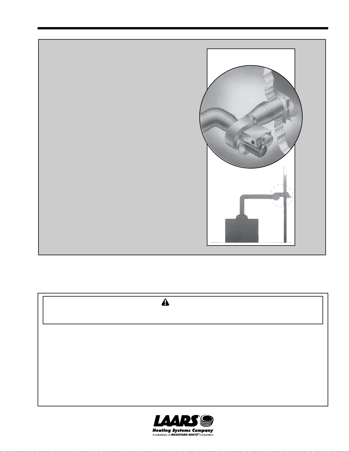
12. Laars’ vent pipe reducers to be installed as
shown in Figure 1.
13. Allow for a minimum of 18" (457mm) vertical
rise off the top of the appliance before the vent
makes a 90 degree elbow to the horizontal (see
Figure 1).
14. Vent pipe shall not be run through an unheated
space or interior part of an open chimney unless
the vent pipe is insulated.
15. Plantheventsystemsothatcoderequiredclearances
are maintained from plumbing and wiring.
16. The Mighty Venter must be mounted so that the
shaft of the motor remains horizontal to prevent
bearing wear and for proper Fan Proving Switch
operation.
17. Ambient temperature surrounding Mighty Venter
must not exceed 104°F (40°C).
18. To prevent personal injury and equipment
damage, disconnect power supply to boiler or
heater when working on Mighty Venter.
19. Make certain the power supply is adequate for
Mighty Venter motor requirements. Do not add
the Mighty Venter to a circuit where the total
load is unknown.
20. IMPORTANT: The following clearances to
combustible materials must be maintained for the
Mighty Venter: sides: 6 inches (152mm); back:
8 inches (203mm).
SECTION 2.
Side Wall Vent Hood Location
If possible, locate the side wall vent hood on a
wall least prone to high winds. This will diminish
the possibility of appliance gas valve interruption
during periods of winds in excess of 40 MPH
(64kmh). The vent hood location must also be in
compliance with the following:
1. Vent hood shall be a minimum of 7 feet (2.1m)
above grade when located adjacent to a public
walkway.
2. Vent hood shall be a minimum of 4 feet (1.2m)
below, 4 feet (1.2m) horizontally from or 3 feet
(0.9m) above any door, window or gravity air
inlet into the building. Vent hood shall not
terminate less than 3 feet (0.9m) from any other
building opening or any gas service regulator.
3. Vent hood shall be installed no closer than 3 feet
(0.9m) from an inside corner of an L-shaped
structure.
4. Vent hood shall be installed at least 3 feet (0.9m)
above any forced air inlet located within 10 feet
(3m). Vent hood shall not terminate less than
6 feet (1.8m) from a combustion air inlet of
another appliance.
5. Vent Hood shall not terminate directly above a
gas utility meter or service regulator.
6. Do not install the vent hood closer than 2 feet
(0.6m) from an adjacent building.
SECTION 3.
Installation
3a. Inspection and Unpacking
Immediately after receiving your Mighty Venter
kit, inspect the shipment packaging and record any
damage on the shipping documents. Unpack the
equipment and carefully inspect for obvious damage
due to shipment. If any damage has occurred, YOU
must file a claim with the transporter, since they will
not accept a claim from the shipper (Laars).
Cartons containing the following should be
included in the Mighty Venter Kit:
1. MightyVenter(eitherMV2,MV3,MV4orMV5).
2. Vent Hood

Mighty Venter Power Vent Systems Page 5
Figure 1. Vent hood locations.
Table 3. Vent Pipe Reducer Kit.
3. Vent Pipe Reducers
The applicable Part Numbers for the above are
listed in Table 2.
Carton #1 Carton #2 Carton #3
Boiler Mighty Power Mighty Vent Vent Pipe
Model Venter Kit Vent Venter Hood Reducer Kit
Size Order # Model Part # P/N Part #
500 20069301 MV2 20032600 D2000401 20070901
600 20069302 MV3 20032700 D2000402 20070902
715 20069303 MV3 20032700 D2000402 20070902
850 20069304 MV4 20032800 D2000402 20070903
1010 20069305 MV4 20032800 D2000402 20070904
1200 20069306 MV5 20032900 D2000403 20070905
1430 20069307 MV5 20032900 D2000403 20070906
1670 20069308 MV5 20032900 D2000403 20070907
1825 20069309 MV5 20032900 D2000403 20070906
NOTES:
1. Mighty Venter Kit #20069301 also includes the D2000500
transition ring for connection from Mighty Venter to vent hood.
(see note #7 on Figure 2 for more information).
2. Carton #1 includes Installation Instructions. Carton #2
includes one Installation Manual (specific to the Vent Hood). If
any items are missing from the package, contact Laars. Be
prepared with your purchase order number and the order
number on the shipping documents.
3. The contents of the “vent pipe reducer kit” are shown in Table
3.
Table 2. Part Numbers.
Boiler
Model
Vent Pipe
Reducer Kit
Part No.
Qty of
Reducers
In Box
REDUCERS IN CARTON
#1
Size Part No. #2
Size Part No. #3
Size Part No. #4
Size Part No.
500 20070901 2 10-8 D2000302 8-6 D2000301
600 20070902 2 12-10 D2000303 10-8 D2000302
715 20070902 2 12-10 D2000303 10-8 D2000302
850 20070903 2 14-10 D2000304 10-8 D2000302
1010 20070904 4 16-14 D2000306 14-12 D2000305 12-10 D2000303 10-8 D20000302
1200 20070905 2 16-14 D2000306 14-10 D2000304
1430 20070906 2 18-14 D2000307 14-10 D2000304
1670 20070907 3 18-14 D2000307 14-12 D2000305 12-10 D2000303
1825 20070906 2 18-14 D2000307 14-10 D2000304
Dimensions shown in feet (m).
Vent Hood
7 (2.1) Minimum
Above Public
Walkway
Vent Hood
Vent Hood
1 (0.3) Above Grade
4 (1.2)
Minimum
Vent Hood Must Be
Mounted 4 (1.2)
Minimum Below Windows
3 (0.9m) Minimum
Vent Hood
4 (1.2)
Minimum
6 (1.8) Above Any
Outside Air Intake
Within 10 (3.0)
Vent
Hood

LAARS Heating Systems
Page 6
Table 4.
NOTES:
1. The asterisk (*) denotes parts that are
included with the Mighty Venter kit.
2. To calculate the equivalent vent pipe
length, add the straight pipe plus 10 feet
(3.0m) for every 90° elbow and 5 feet
(1.5m) for every 45° elbow.
3. In order to use 100-foot (30.5m)
equivalent length of vent pipe with the
model 1670 boiler, consult factory. A
14 inch (356mm) vent pipe may be used.
4. To be used for single boiler installation
only.
5. Note that the Mighty Venter diameters
shown are for both the inlet and the
outlet of the Mighty Venter.
6. The vent pipe reducer kit includes item
D. And one of: Item E, Item G, Item H.
(As shown: varies per model.)
7. Reference Item “L” is used only with the
500 boiler. It is included with the
20069301 Mighty Venter kit.
8. The vent system must be adequately
supported to prevent sagging. But in no
case shall the supports be less than
every three feet (0.9m).
9. The venting system must be sloped
upward not less than ¼ inch per foot
from the furnace to the vent terminal. The
vent system must be installed to prevent
collection of condensate.
10.Side wall vent hood location: Read all
installation/operation information
concerning vent hood location before
installing.
E*
D* C
A
18" (457mm) minimum
recommended rise
before elbowing to
horizontal run.
K
Equivalent Pipe Length
Calculate as per Notes 2
and 3 below.
Minimum equivalent vent
pipe length is 11' (3.4m)
(Slope: Note 9)
(Supports: Note 8)
Vent pipe is customer supplied
G* H*
FJ
*B
Reducer dimensions
For all sizes
(#1, #2, #3, #4)
B*
J
(Note 7)
Clearances to
combustibles:
6" (152mm) sides
8" (203mm) rear
L* M*
P
N
(Note 10)
Side View
Figure 2. Part identification.
A NOTE 1 B C NOTE 6 D E F G H J K L, M N P
* * *
Boiler
Model
Size
Mighty
Venter Kit
Order No.
Power
Venter
Model
Ref.
Boiler
Vent
Outlet
In. (mm)
Vent Pipe
Reducer Kit
Part No.
Reducer Sizes Included In Reducer Kit Mighty
Venter
Outlet
& Inlet
In. (mm)
Equivalent
Pipe
Length
(Max)
ft. (m)
Vent
Hood
P/N
Vent
Hood
Dia.
in. (mm)
Rough-In
Dimension
In. (mm)
Size
#1 Size
#2
Ref. Vent
Pipe Dia.
In. (mm)
Size
#3 Size
#4
500 20069301 MV-2 10 (254) 20070901 10-8 -- 8 (203) 8-6 -- 6 (152) 100 (30.5) D2000401 8.50 (216) 9.0 (229)
600 20069302 MV-3 12 (305) 20070902 12-18 10-8 8 (203) -- -- 8 (203) 100 (30.5) D2000402 10.12 (257) 10.62 (270)
715 20069303 MV-3 12 (305) 20070902 12-18 -- 10 (254) 10-8 -- 8 (203) 100 (30.5) D2000402 10.12 (257) 10.62 (270)
850 20069304 MV-4 14 (356) 20070903 14-10 -- 10 (254) 10-8 -- 8 (203) 100 (30.5) D2000402 10.12 (257) 10.62 (270)
1010 20069305 MV4 16 (406) 20070904 15-14 14-12 12 (254) 12-10 10-8 8 (203) 100 (30.5) D2000402 10.12 (257) 10.62 (270)
1200 20069306 MV-5 16 (406) 20070905 15-14 14-10 10 (254) -- -- 10 (254) 100 (30.5) D2000403 13.25 (337) 13.75 (349)
1430 20069307 MV-5 18 (457) 20070906 18-14 14-10 10 (254) -- -- 10 (254) 100 (30.5) D2000403 13.25 (337) 13.75 (349)
1670 20069308 MV-5 18 (457) 20078907 18-14 14-12 12 (305) 12-10 -- 10 (254) 80 (24.4) D2000403 13.25 (337) 13.75 (349)
1825 20069309 MV-5 18 (457) 20070906 18-14 -- 14 (356) 14-10 -- 10 (254) 100 (30.5) D2000403 13.25 (337) 13.75 (349)

Mighty Venter Power Vent Systems Page 7
Figure 4. Placement of plumber's strap or threaded rod for MV4 and MV5.
Figure 3. Placement of plumber's strap or threaded rod for MV3.
Plumber's Strap or Threaded Rod
3b. Power Venter Mounting
The installer must supply plumber's strap or 1/4
threaded rod with nuts and washers for mounting (see
Figure 3 for MV3, see Figure 4 for MV4 and MV5).
The Mighty Venter may be mounted in any position as
long as the shaft of the motor remains horizontal. The
Mighty Venter housing is single wall, 6 inches
(152mm) must be maintained from all combustible
materials. It is recommended that the Power Venter
be mounted as close as possible to the point
of termination.
Horizontal
Installation Vertical
Installation
Horizontal
Installation Vertical
Installation

LAARS Heating Systems
Page 8
3c. Fan Proving Switch Installation
NOTE: If installing the MV2, the fan proving
switch is factory installed. This section does not apply.
Test Port: the fan proving switch on the MV3,
MV4, and MV5 includes a test port which can be used
to measure the pressure in the switch. The black
plastic cap over this test port must be in place during
regular operation of the Mighty Venter.
The fan proving switch installation procedure for
the MV3 is as follows:
1. Mount the fan proving switch to a flat surface
within 4 feet (1.2m) of the Mighty Venter.
NOTE: It is important that the fan proving
switch be mounted in a vertical position.
2. Connect the ¼" aluminum tubing from the fan
proving switch to the Mighty Venter housing
using provided fittings.
The fan proving switch installation procedure for
the MV4 and MV5 is as follows:
1. Mount the supplied electrical box to a flat
surface within 4 feet (1.2m) of the Mighty
Venter. NOTE: It is important that the electrical
box is mounted so that the fan proving switch is
in a vertical position.
2. Connect the ¼" aluminum tubing from the fan
proving switch to the Mighty Venter housing
using provided fittings.
3d. Wiring
WARNING
All wiring from the Mighty Venter to the appliance
must be in compliance with local codes or in their
absence, the National Electric Code (NFPA #70) in
the United States and the CSA C22.1 Electrical
Code in Canada
a) Connect the black and white (120 VAC) leads
from the Mighty Venter to the boiler control box.
Connect these leads with wire nuts to the boiler
circuit as shown in Figure 5. NOTE: If correctly
wired (as shown in Figure 5), the power to the
Mighty Venter will be disconnected if the boiler
toggle switch is turned off.
b) Connect the red, blue and orange (24 VAC)
wires to the terminal blocks as shown in
Figure 5.
c) Remove the factory-installed jumper from
between boiler terminals 3 and 4.
Ensure that the current capacities of wires,
switches, etc., at 120 VAC meet the ratings as
indicated in Table 5.
Equivalent
Mighty Venter Full Load Currents
Model Motor HP (Amperes - 120VAC)
MV2 1/8 4.4
MV3 1/4 5.8
MV4 1/3 7.2
MV5 116
Table 5. Electrical Ratings.

Mighty Venter Power Vent Systems Page 9
Figure 5. Mighty Therm System 9, 11 or 16, Models 500-1825, wiring with Mighty Venter.
Mighty Therm Mighty Venter
Junction Box
Mighty Venter
NOTE:
The black (BK) and white (W) leads from
the Mighty Venter to the junction box
do not require field wiring on Model MV2.
Color Legend
BK - Black
W-White
R-Red
Y-Yellow
BL - Blue
BR - Brown
O-Orange
G-Green
P-Purple
BR/Y - Brown with Yellow
BL/Y - Blue with Yellow
Factory Wiring
24V
115V
Field Wiring
24 V
115V
HOT 120V NEUTRAL

LAARS Heating Systems
Page 10

Mighty Venter Power Vent Systems Page 11

Laars Warranty
Mighty Venter Power Vent System
This Laars product is
backed by this warranty
to assure your complete satisfaction.
Laars warrants the components of this product either for one year from date of installation or 18 months from date of
purchase,whichever comes first. This warranty covers defects in material and workmanship.Products thatare tampered
with, damaged,ordefective due to malfunctioning appliances are not covered under thiswarranty. Thiswarranty doesnot
cover the complete power vent system, only the defective parts.
The above warranty applies only if the installation and operation instructions applicable to the model are expressly and
completely followed. These instructions are furnished with the unit and are also available by writing the Laars factory. The
liability of Laars shall not exceed the repair or replacement of defective parts, excluding field labor.
FOB Factory: Rochester, NH or Oakville, Ontario, Canada.
Return Instructions: After faulty component is determined, ship inoperative part with proofs of purchase and installation
date, transportation prepaid, directly to one of the addresses listed below, Attention: Service Manager. Please include date
code of product with the defective component. The date code is listed on the product nameplate, which is located on the
electrical box or on the drip shield surrounding the motor. A copy of the original installation receipt must also be included
with returned components.
This warranty gives you specific legal rights, and you may also have other rights which vary from state to state and by
province. Some states and provinces do not allow the exclusion or limitation of incidental damages, so the above limitation
or exclusion may not apply to you.
H2015300B
800.900.9276 • Fax 800.559.1583 (Customer Service, Service Advisors)
20 Industrial Way, Rochester, NH 03867 • 603.335.6300 • Fax 603.335.3355 (Applications Engineering)
9 Brigden Gate, Halton Hills, Ontario, Canada L7G 0A3 (905) 203-0600 Fax: (905) 636-0666
www.Laars.com Litho in U.S.A. © Laars Heating Systems 0810 Document 7008B
This manual suits for next models
3
Table of contents
Other Laars Industrial Equipment manuals