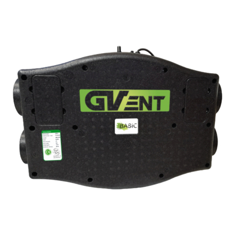
GV-INDUSTRIES CVU User manual

MANUFACTURED BY
CVU
Single flow

CVU
INFORMAÇÕES IMPORTANTES
1
Ler atentamente o manual de instruções antes de tentar instalar ou efetuar a manutenção da ventoinha!
O manual de instruções e as instruções de montagem nele contidas são parte integrante do produto.
equipamento. O manual de instruções contém informações técnicas importantes e instruções para a segu-
rança de funcionamento do ventilador. Ler atentamente as instruções de montagem contidas no manual de
instruções. Conservar o manual de instruções de operação para consulta futura.
Perigo ! Perigo de eletrocussão
– Alta voltagem
Atenção
Elementos Rotativos!
- Este produto pode ser utilizado por crianças com pelo menos 8 anos de idade
de idade, por pessoas com capacidades físicas e/ou mentais físicas e/ou mentais, e por pessoas sem qualquer
experiência ou compreensão do funcionamento do produto, se supervisionadas ou instruídas por um adulto
competente sobre a utilização segura do produto, de modo a que compreendam os riscos de funcionamento
relevantes. Este produto não é um brinquedo e as crianças não devem brincar com ele. As crianças não devem
ser autorizadas a limpar ou efetuar a manutenção do sem a supervisão de um adulto.
- O ventilador destina-se a uma instalação permanente e ligação ao sistema elétrico do edifício.
O sistema elétrico do edifício ligado à ventoinha deve ser capaz de interromper o contacto de tensão de
tensão em todos os pólos de comutação para isolar completamente o o ventilador da energia durante
condições de sobretensão de Categoria III Categoria III, de acordo com os regulamentos regulamentos de
engenharia elétrica aplicáveis.
- O ventilador foi concebido para ser instalado a uma altura considerável, ou seja, 2,3 m acima do pavimento.
O ventilador ventilador só pode ser instalado numa posição e numa e numa orientação especificadas no
manual de instruções, tendo em conta a entrada necessária do cabo de alimentação na na caixa do ventilador.
Informações importantes
Precauções de segurança
Aplicação e condições de funcionamento
Acessórios
Sequência de montagem
Ligações elétricas
Manutenção e limpeza
Termos e condições da garantia
01
01
02
03
03
04
05
05
Contatos 15
Important information
Scurity precautions
Application and operating conditions
Accessories
Assembly sequence
Electrical connections
Maintenance and cleaning
Warranty terms and conditions
06
06
07
07
08
09
09
10
Contacts 15

2
Antes de proceder à manutenção do ventilador, isolá-lo da tensão de rede com o disjuntor. Proteger o disjun-
tor contra uma operação inadvertida.
• A conceção da instalação do ventilador deve impedir a entrada de gás de combustão no compartimento a
partir de condutas de exaustão de gás de combustão abertas e de aparelhos que funcionem com as aberturas
de gases de combustão e de aparelhos que funcionem com as condutas abertas.
• Nunca tentar modificar ou alterar o ventilador sem autorização.
• Antes de instalar o ventilador, verificar a capacidade de carga da subestrutura da instalação.
A fixação incorrecta pode provocar danos ou avarias no ventilador e riscos para as pessoas que se encontram
nas proximidades.
O ventilador pode ser perigoso se for utilizado para outros ns que não os previstos
ou se for instalado por pessoal não qualicado.
- O ventilador central destina-se a tratar o ar interior de qualidade normal ou com baixo teor de poeira (com
um tamanho de partícula < 10 m) com baixa agressividade e humidade. O ventilador central destina-se a
funcionar em condições climatéricas condições climatéricas temperadas e dentro dos limites de desempenho
especificados no catálogo de produtos.
- O ventilador central só pode ser operado numa instalação interior permanente.
- A temperatura máxima do meio tratado pelo exaustor de ar e a temperatura ambiente máxima
ambiente são +40°C.
- O ventilador central é um dispositivo IPX2 e da classe de proteção I.
- O ventilador só deve ser operado de acordo com a sua utilização prevista e dentro dos limites de desempen-
ho especificados na placa de identificação.
- Ligar o ventilador à rede eléctrica do edifício (sistema elétrico) com o seguinte cabo de alimentação: NYM-O
5x1,5 mm² (H07V-K 5x1,5 mm²) ou com dois cabos NYM-O 3x1,5 mm² (H07V-K 3x1,5 mm²), consoante os
acessórios opcionais fornecidos.
Não utilizar o ventilador para manipular o ar com os seguintes conteúdos:
- contaminantes viscosos suscetível de se depositarem no ventilador,
- contaminantes corrosivos que podem degradar o ventilador,
- contaminantes inflamáveis, incluindo gases, vapores, névoas ou partículas que possam formar misturas
explosivas com o ar.
- Os aparelhos equipados com rolamentos de esferas foram concebidos para uma vida útil mínima de 30 000
horas no ciclo de funcionamento S1 com a potência máxima e a temperatura ambiente máxima.
- O sistema de controlo deve evitar ciclos de alimentação extremamente frequentes.
- Conservar os ventiladores na sua embalagem original, num local seco e abrigado.
- Os limites de temperatura ambiente para o transporte e armazenamento são de -20 °C a +40 °C.
- Proteger contra choques. Transportar o ventilador na sua embalagem de origem.
- Se o tempo de armazenamento for superior a 1 ano, os rolamentos do motor do ventilador devem ser testa-
dos rodando o rotor do ventilador à mão antes da instalação.
O rotor do ventilador deve funcionar sem problemas.
- Eliminar o ventilador no final da sua vida útil, de acordo com as leis de proteção ambiental e de gestão de
resíduos.
- Caso ocorram danos causados por transporte, manuseamento, armazenamento ou colocação em funciona-
mento incorreto, estes danos não estão abrangidos pela garantia.

3
Acessórios opcionais disponíveis:
Bloco de terminais (versão standard). Ligar o ventilador equipado com o bloco de terminais como indicado no
diagrama de ligações eléctricas, ver Fig. 2.
O ventilador central é ligado e desligado por um interrutor on/off separado instalado na linha de alimentação
eléctrica do edifício (e não incluído no produto). A velocidade de rotação pode ser definida de forma perma-
nente, dependendo da velocidade de rotação, dependendo da ligação, ou ajustada com um interrutor adicional
dedicado a motores monofásicos de três velocidades.
Higróstato + Temporizador ('HT'). Ligar o ventilador central ao temporizador de paragem retardada como
indicado no diagrama de ligações eléctricas, ver Fig. 3.
A gama de funcionamento do sensor de humidade do ar é de 0% a 100% de humidade relativa.
O nível de humidade deve ser regulado por meio de um botão situado na parte da frente da caixa do venti-
lador. O conjunto inclui um interrutor de dois botões com uma caixa de montagem de superfície. Depois de
colocar a chave esquerda na posição "ON", o ventilador começa a funcionar na 1ª velocidade.
Quando a humidade ultrapassa o valor definido pelo botão, o ventilador aumenta automaticamente a veloci-
dade (2ª velocidade). Quando a humidade descer abaixo do valor definido, o ventilador volta a funcionar em 1ª
velocidade. Pressionando uma vez a tecla "TURBO", ativa-se o modo de ventilação de 15 minutos (3ª veloci-
dade). Mantendo pressionada a tecla "TURBO" durante mais de 5 segundos ativa o modo de ventilação
durante 1 hora.
Para interromper o modo de ventilação de uma hora, manter a tecla "TURBO" pressionada durante mais de 5
segundos. Colocar a tecla esquerda na posição "OFF" desliga o ventilador e repõe a contagem decrescente do
tempo de ventilação atualmente iniciado.
Nota! A humidade relativa recomendada em habitações unifamiliares é de 40 - 60%.
- Determinar exatamente onde e como o ventilador será instalado. São permitidos dois métodos de instalação:
- Com a ajuda da linha e do pino de gancho incluídos no conjunto. De seguida, deve ser feito um furo Ø8 mm
para a cavilha na viga de madeira do telhado ou na estrutura da viga do teto, diretamente por cima do venti-
lador. A altura do ventilador pode ser ajustada com o comprimento da linha. O método de instalação é mostra-
do na Figura 9.
- O ventilador também pode ser montado diretamente na parede ou no teto. Antes, fazer furos para os parafu-
sos ou cavilhas na caixa do ventilador, nos locais indicados na Figura 10.
- Preparar o cabo de alimentação. Utilizar NYM-O 5x1,5 mm² (H07V-K 5x1,5 mm²) ou 2x NYM-O 3x1,5 mm²
(H07V-K 3x1,5 mm²), consoante os acessórios opcionais fornecidos.
- Rodar os grampos de fixação da tampa (3) com uma chave de fendas ou outra ferramenta com uma haste
rígida (Fig.6), e depois retirar a cobertura do ventilador (6).
- Retirar as tampas do sistema eletrónico (1 e 9) fixadas com parafusos.
- Passar o cabo de alimentação (no caso da versão HT, também o cabo de controlo) através dos casquilhos de
borracha (7). As distâncias devem facilitar a ligação às pinças de alimentação (8). O comprimento do cabo com
isolamento duplo deve ser de, pelo menos 10 mm no interior da câmara.
NOTA! O cabo de alimentação deve ser selado para evitar a entrada de água ao longo do cabo nas partes sob
tensão.

4
- Ligue o cabo de alimentação de acordo com o esquema de ligações da respectiva opção de acessórios e fixe-o
com as braçadeiras (2) para evitar que seja projetado.
- Montar e aparafusar as tampas do sistema eletrónico (1 e 9).
- Inserir os anéis (14) e os orifícios de ligação (13) nas aberturas de entrada do ventilador seleccionadas. Depois
de inserir o orifício de ligação no anel, protegê-lo contra o deslizamento, rodando-o no sentido dos ponteiros
do relógio (Fig. 7) e, em seguida, fixando-o com o parafuso de rosca (16). Antes de rodar o tubo de ligação,
bloquear o anel com a chave (15) fornecida com o kit.
As aberturas não utilizadas devem ser protegidas com as tampas (11) incluídas no conjunto. Se for utilizado um
bocal de entrada Ø125,deve ser removido com, por exemplo, uma serra de metal (Fig.8).
- Fixar a caixa do ventilador (4) em função do método de instalação escolhido.
Antes de fixar o ventilador, é necessário: remover objectos estranhos do interior do ventilador; verificar se o
rotor roda livremente, colocando-o em movimento com a mão.
Recomenda-se que o ventilador seja ligado ao sistema de condutas através de uma ligação de tubo flexível!
- Colocar a tampa principal (6) no ventilador.
O arranque do ventilador central só pode ser efectuado com todas as precauções de segurança tomadas e
todos os riscos eliminados. Colocar o ventilador central em funcionamento. Verificar
se funciona corretamente e se o ar é tratado de forma eficaz.
Verificar o funcionamento do ventilador central (ruído, vibração, consumo de energia, possibilidade de contro-
lar a velocidade de rotação).
O ventilador só pode ser utilizado com condutas de ventilação ou tampões para as aberturas de ligação insta-
lados. O comprimento mínimo da conduta de ventilação é de 1,5 m. Tenha em atenção que o utilizador do
ventilador central é responsável pelo cumprimento das normas de de segurança em vigor e pode ser
responsabilizado por ferimentos acidentais ou morte causados pela não disponibilização do equipamento de
segurança necessário.
- As ligações eléctricas e a colocação em funcionamento do ventilador só devem ser efectuadas por electricis-
tas profissionais qualificados.
- Seguir sempre as normas aplicáveis, os regulamentos de segurança e os requisitos técnicos especificados
pela eléctrica!
- A linha de alimentação eléctrica para o ventilador requer um disjuntor multipolar / interrutor de isolamento
com um intervalo mínimo de rutura de contacto de 3 mm (ref. PN-001).
- O sistema de rede, a tensão e a frequência devem corresponder aos valores nominais do ventilador.
- Ao ligar um interrutor de controlo de botão duplo, deve ser feita uma ponte entre os terminais de entrada.
Para fazer a ponte e ligar o interrutor, utilizar um cabo com o mesmo diâmetro (aplica-se à versão HT).
- O diagrama de ligação do sensor de humidade é apresentado na Figura 4 (aplica-se à versão HT).
As dimensões dos modelos específicos de ventiladores são mostradas na Fig. 5.

5
- Utilizar calçado e luvas de proteção durante a manutenção!
- Durante todos os trabalhos de manutenção e conservação, devem ser respeitadas as normas eléctricas e de
SST (PN-IEC 60364-3).(PN-IEC 60364-3).
- Antes de proceder à manutenção do ventilador, isolá-lo da tensão de rede com o disjuntor. Proteger o disjun-
tor contra uma operação inadvertida!
- As condutas do ventilador devem estar livres de corpos estranhos: perigo de ferimentos devido a objectos
projectados a alta velocidade!
- Não efetuar qualquer manutenção com o ventilador em funcionamento ou sob tensão!
- Se forem sentidas ou ouvidas vibrações excessivas, a inspeção técnica deve ser realizada por um eletricista
qualificado.
- Os intervalos de manutenção dependem da contaminação atual do rotor do ventilador e não devem ser
superiores a 6 meses!
- Verificar o rotor do ventilador quanto a fissuras.
- O fabricante não se responsabiliza por quaisquer danos resultantes de reparações não profissionais.
- Limpar as partes visíveis da caixa com um pano húmido.
- Limpar o interior do ventilador:
- Retirar a tampa da ventoinha principal (6), rodando primeiro os grampos de fixação (3)
com uma ferramenta rígida com cabeça de pino e depois a tampa do rotor (5) fixada com parafusos.
- Limpar a roda móvel e o interior da caixa do ventilador com um pano húmido.
- Deixar secar a ventoinha.
- Voltar a montar a tampa do rotor e a tampa principal da ventoinha.
- Não utilizar solventes de tinta agressivos!
- Não limpar com uma máquina de limpeza de alta pressão ou com jactos de água fortes!
- Limpar com cuidado para evitar a entrada de água no motor ou na caixa de terminais.
- Manter sempre limpa a grelha à entrada das condutas do ventilador.
1. O período de garantia para o bom funcionamento do ventilador é de 2 anos, a partir da data de venda.
2. Os direitos e obrigações da garantia serão nulos e sem efeito , sem a apresentação de uma prova de compra
(recibo ou fatura)
3. A garantia cobre todos os defeitos e danos imputáveis ao fabricante.
4. Para efeitos de garantia, o produto deve ser entregue ao fabricante ou ao vendedor original.
5. O fabricante compromete-se a reparar o produto ou a substituí-lo por um novo.
6. A garantia não cobre nenhum dos seguintes casos: danos no produto imputáveis a uma
instalação incorrecta ou não qualificada, funcionamento contra a utilização prevista, transporte, armazena-
mento e/ou manutenção incorrectos, quaisquer falhas atribuíveis a reparações não autorizadas ou quaisquer
danos acidentais.
7. A garantia não cobre a instalação ou a manutenção do produto.

6
Não eliminar os resíduos de equipamento elétrico juntamente com o lixo doméstico.
O símbolo do caixote do lixo barrado com uma cruz neste produto significa que se trata de resíduos de equipa-
mentos eléctricos e electrónicos (REEE) no final da sua vida útil e que não deve ser eliminado com o lixo
doméstico. Elétrico e eletrónico (REEE) no fim da sua vida útil e não deve ser eliminado com o
lixo doméstico.
O símbolo do caixote do lixo barrado com uma cruz indica que o produto está sujeito a planos
obrigatórios de separação de resíduos para uma eliminação correcta. O produto é fabricado a
partir de materiais e componentes recicláveis. O utilizador do produto é obrigado a entregar o
produto que se tornou REEE a uma unidade de recolha de REEE. Os operadores de unidades de
recolha de REEE, incluindo locais de recolha de REEE, revendedores de produtos e outros locais
de recolha de REEE geridos pelas autoridades locais, formam um sistema adequado de elimi-
nação de resíduos. A eliminação adequada de REEE ajuda a evitar efeitos nocivos para os seres
humanos e para o ambiente devido ao risco causado por componentes perigosos que este produto possa
conter. O agregado familiar desempenha um papel importante na contribuição para a reutilização e recuper-
ação, incluindo a reciclagem, de aparelhos usados, e é a fase em que se criam atitudes que têm impacto na
preservação do ser comum e do ambiente natural limpo. As famílias estão entre os principais consumidores de
pequenos electrodomésticos e equipamentos.
- This product may be used by children at least 8 years of age
of age, by persons with physical and/or mental capabilities, and by persons with no experience or under-
standing of the operation of the product, if supervised or instructed by a competent adult in the safe use of
the product so that they understand the relevant operating risks. This product is not a toy and children
should not play with it. Children should not be allowed to clean or maintain the fan without adult supervision.
- The fan is intended for permanent installation and connection to the building's electrical system.
The building electrical system connected to the fan must be capable of interrupting the voltage contact on
all switch poles to completely isolate the fan from power during Category III overvoltage conditions in
accordance with applicable electrical engineering regulations.
- The fan is designed to be installed at a considerable height, i.e. 2.3 m above the floor. The fan may only be
installed in a position and in an orientation specified in the instruction manual, taking into account the
required power cable entry into the fan housing.
Before servicing the fan, isolate it from the mains voltage with the circuit breaker. Protect the circuit breaker
against inadvertent operation.
- The design of the fan installation must prevent flue gas from entering the room from open flue gas exhaust
ducts and from appliances operating with flue gas vents and appliances operating with open ducts.
- Never attempt to modify or alter the fan without authorisation.
- Before installing the fan, check the load capacity of the installation substructure.
Incorrect fixing may cause damage or malfunction of the fan and risk to persons in the vicinity.
CVU
INFORMAÇÕES IMPORTANTES
Read the instruction manual carefully before attempting to install or service the fan! Globovac is not responsi-
ble or liable for any damage resulting from incorrect operation, unintended use or repair or unauthorized
repair or modification of the product.
The instruction manual and the assembly instructions contained therein are an integral part of the product.
equipment. The operating instructions contain important technical information and instructions for the safe
operation of the fan. Read the installation instructions in the operating instructions carefully. Keep the oper-
ating instructions for future reference.
Danger! Danger of electrocution
High voltage
Attention
Rotating elements!

The fan may be dangerous if used for purposes other than those intended or if installed
by unqualied personnel or if installed by unqualied personnel.
- The central fan is intended to treat indoor air of normal quality or low dust content (with a particle size < 10
m) with low aggressiveness and humidity. The central fan is intended to operate in temperate climatic condi-
tions and within the performance limits specified in the product catalogue.
- The central fan may only be operated in a permanent indoor installation.
- The maximum temperature of the medium treated by the exhaust fan and the maximum ambient tempera-
ture
ambient temperature are +40°C.
- The central fan is an IPX2 device and of protection class I.
- The fan must only be operated in accordance with its intended use and within the performance limits speci-
fied on the nameplate.
- Connect the fan to the building's electrical network (electrical system) with the following power cable:
NYM-O 5x1.5 mm² (H07V-K 5x1.5 mm²) or with two NYM-O 3x1.5 mm² cables (H07V-K 3x1.5 mm²), depending
on the optional accessories supplied.
Do not use the fan to handle air with the following contents:
- viscous contaminants that may deposit on the fan,
- corrosive contaminants which may degrade the fan,
- flammable contaminants, including gases, vapours, mists or particles that may form explosive mixtures with
the air.
- Appliances equipped with ball bearings are designed for a minimum life of 30 000 hours on duty cycle S1 at
maximum power and maximum ambient temperature.
- The control system must avoid extremely frequent power cycles.
- Store the fans in their original packaging in a dry and sheltered place.
- The ambient temperature limits for transport and storage are -20 °C to +40 °C.
- Protect against shocks. Tr
- Protect against shocks. Transport the fan in its original packaging.
- If the storage time is longer than 1 year, the fan motor bearings must be tested by turning the fan impeller
by hand before installation.
The fan impeller should run smoothly.
- Dispose of the fan at the end of its service life in accordance with environmental protection and waste
management laws.
- If damage occurs due to incorrect transport, handling, storage or commissioning, this damage is not covered
by the warranty.
Optional accessories available:
Terminal block (standard version). Connect the fan fitted with the terminal block as shown in the wiring
diagram, see Fig. 2.
The central fan is switched on and off by a separate on/off switch installed in the building's power supply line
(not included in the product). The rotation speed can be set permanently, depending on the connection, or
adjusted with an additional interrupter dedicated to single-phase three-speed motors.
Hygrostat + Timer ('HT'). Connect the centre fan to the delayed stop timer as shown in the wiring diagram, see
Fig. 3.
7

The operating range of the air humidity sensor is from 0% to 100% relative humidity.
The humidity level must be adjusted by means of a knob located on the front of the fan housing. The set
includes a two-button switch with a surface mounting box. After turning the left-hand switch to the "ON"
position, the fan starts running at 1st speed.
When the humidity exceeds the value set by the button, the fan automatically increases the speed (2nd
speed). When the humidity drops below the set value, the fan returns to 1st speed. Pressing the "TURBO"
button once activates the 15-minute ventilation mode (3rd speed). Pressing and holding the "TURBO" button
for more than 5 seconds activates the ventilation mode for 1 hour.
To interrupt the one-hour ventilation mode, keep the "TURBO" key pressed for more than 5 seconds. Placing
the left-hand key in the "OFF" position switches the fan off and resets the countdown of the currently started
ventilation time.
Note! The recommended relative humidity in single-family houses is 40 - 60%.
- Determine exactly where and how the fan will be installed. Two installation methods are allowed:
- With the help of the line and hook pin included in the set. A Ø8 mm hole for the dowel must then be drilled in
the wooden roof beam or ceiling beam structure directly above the fan. The height of the fan can be adjusted
with the length of the line. The installation method is shown in Figure 9.
- The fan can also be mounted directly on the wall or ceiling. Beforehand, drill holes for the screws or bolts in
the fan housing at the locations shown in Figure 10.
- Prepare the power cable. Use NYM-O 5x1.5 mm² (H07V-K 5x1.5 mm²) or 2x NYM-O 3x1.5 mm² (H07V-K 3x1.5
mm²), depending on the optional accessories supplied.
- Turn the cover fixing clips (3) with a screwdriver or other tool with a rigid rod (Fig.6), then remove the fan
cover (6).
- Remove the electronics covers (1 and 9) secured with screws.
- Pass the power cable (in the case of the HT version, also the control cable) through the rubber bushes (7).
The distances must facilitate the connection to the power clamps (8). The length of the double insulated cable
must be at least 10 mm inside the chamber.
NOTE! The power cable must be sealed to prevent water from entering the live parts along the cable.
- Connect the power cable according to the connection diagram of the respective accessory option and secure
it with the clamps (2) to prevent it from being projected.
- Mount and screw on the electronic system covers (1 and 9).
- Insert the rings (14) and the connection holes (13) into the selected fan inlet openings. After inserting the
connection hole into the ring, secure it against slipping by turning it clockwise (Fig. 7) and then securing it with
the threaded screw (16). Before turning the connecting pipe, lock the ring with the spanner (15) supplied with
the kit.
Unused openings must be protected with the covers (11) included in the kit. If a Ø125 inlet nozzle is used, it
must be removed with, for example, a metal saw (Fig.8).
- Attach the fan housing (4) depending on the installation method chosen.
Before attaching the fan, it is necessary to: remove foreign objects from inside the fan; check that the impeller
rotates freely by moving it with your hand.
It is recommended that the fan be connected to the duct system by means of a flexible pipe connection!
- Place the main cover (6) on the fan.
8

Starting the central fan can only be carried out with all safety precautions taken and all risks eliminated. Start
up the central fan. Check
that it works correctly and that the air is treated effectively.
- Wear protective footwear and gloves during maintenance!
- During all maintenance and servicing work, the electrical and OSH standards (PN-IEC 60364-3) must be
observed.(PN-IEC 60364-3).
- Before servicing the fan, isolate it from the mains voltage with the circuit breaker. Protect the circuit breaker
against inadvertent operation!
- The ducts of the fan must be free of foreign bodies: danger of injury from objects thrown at high speed!
- Do not carry out any maintenance while the fan is running or under power!
- If excessive vibrations are felt or heard, the technical inspection must be carried out by a qualified electrician.
- Maintenance intervals depend on the current contamination of the fan impeller and should not be longer
than 6 months!
- Check the fan impeller for cracks.
- The manufacturer is not liable for any damage resulting from unprofessional repairs.
Check the operation of the central fan (noise, vibration, energy consumption, possibility to control the rota-
tion speed).
The fan may only be used with ventilation ducts or plugs for the connection openings installed. The minimum
length of the ventilation duct is 1.5 m. Please note that the user of the central fan is responsible for compli-
ance with the applicable safety regulations and may be held liable for accidental injury or death caused by
failure to provide the necessary safety equipment.
- Electrical connections and commissioning of the fan must only be carried out by qualified professional electri-
cians.
- Always follow the applicable standards, safety regulations and technical requirements specified by the
electrician!
- The power supply line for the fan requires a multi-pole circuit breaker / isolating interrupter with a minimum
contact breakage gap of 3 mm (ref. PN-001).
- The mains system, voltage and frequency must correspond to the rated values of the fan.
- When connecting a double button control switch, a bridge must be made between the input terminals.
To bridge and connect the switch, use a cable with the same diameter (applies to the HT version).
- The humidity sensor connection diagram is shown in Figure 4 (applies to HT version).
DIMENSIONS
The dimensions of the specific fan models are shown in Fig. 5.
9
- Clean the visible parts of the housing with a damp cloth.
- Clean the inside of the fan:
- Remove the main fan cover (6) by first turning the fixing clamps (3) with a rigid tool with a pin head and
then the rotor cover (5) fixed with screws. with a rigid tool with a pin head and then the impeller cover (5)
fixed with screws.

1. The warranty period for the proper functioning of the fan is 2 years from the date of sale.
2. The rights and obligations of the guarantee will be null and void without the presentation of a proof of
purchase (receipt or invoice).
3. The warranty covers all defects and damages attributable to the manufacturer.
4. For warranty purposes, the product must be delivered to the original manufacturer or seller.
5. The manufacturer undertakes to repair the product or replace it with a new one.
6. The warranty does not cover any of the following: damage to the product attributable to incorrect or
unqualified
incorrect or unqualified installation, operation against intended use, incorrect transport, storage and/or
maintenance, any faults attributable to unauthorised repairs or any accidental damage.
7. The warranty does not cover installation or maintenance of the product
Do not dispose of waste electrical equipment with household waste.
The crossed-out wheeled bin symbol on this product means that it is waste electrical and electronic equipment
(WEEE) at the end of its useful life and should not be disposed of with household waste. Waste electrical and
electronic equipment (WEEE) at the end of its useful life and should not be disposed of with
household waste.
The crossed-out dustbin symbol indicates that the product is subject to mandatory waste
separation plans for proper disposal. The product is manufactured from recyclable materials
and components. The user of the product is obliged to return the product that has become
WEEE to a WEEE collection facility. Operators of WEEE collection facilities, including WEEE
collection sites, product retailers and other WEEE collection sites managed by local authorities,
form a proper waste disposal system. Proper disposal of WEEE helps to avoid harmful effects
on humans and the environment due to the risk caused by hazardous components that this
product may contain. The household plays an important role in contributing to the reuse and recovery, includ-
ing recycling, of used appliances, and is the stage at which attitudes are created that have an impact on
preserving the commons and the clean natural environment. Households are among the main consumers of
small appliances and equipment.
- Clean the impeller and the inside of the fan housing with a damp cloth.
- Allow the fan to dry.
- Refit the impeller cover and the main fan cover.
- Do not use aggressive paint solvents!
- Do not clean with a high-pressure cleaner or strong water jets!
- Clean carefully to prevent water from entering the motor or terminal box.
- Always keep the grille at the entrance to the fan ducts clean.
- Clean the visible parts of the housing with a damp cloth.
- Clean the inside of the fan:
- Remove the main fan cover (6) by first turning the fixing clamps (3) with a rigid tool with a pin head and then
the rotor cover (5) fixed with screws.
with a rigid tool with a pin head and then the impeller cover (5) fixed with screws.
- Clean the impeller and the inside of the fan housing with a damp cloth.
- Allow the fan to dry.
- Refit the impeller cover and the main fan cover.
- Do not use aggressive paint solvents!
- Do not clean with a high-pressure cleaner or strong water jets!
- Clean carefully to prevent water from entering the motor or terminal box.
- Always keep the grille at the entrance to the fan ducts clean.
10

1
7
3
8
2
9
5
6
10
4
11
Fig. 1
L
N
1
2
3
L
N
N
L
BRANCO/ white
CASTANHO/ brown
PRETO/black
BRANCA/white
CASTANHO/brown
PRETA/black
BRANCO / withe
CINZA/gray
PRETO/black
AZUL/blue
AMARELO-VERDE / yellow-green
AZUL/blue
AMARELO-VERDE/ yellow-green
11
22
33
L
N
SL IN1
SL IN2
SL OUT
on/off
impulse
C
O
M
N
C
N
O
1
3
2
Fig. 2
Fig. 3 Fig. 4
VIOLETA/violet
Baixa velocidade Velocidade média Alta velocidade
CONTROLADOR DE SENSOR
DE HUMIDADE
SENSOR CONTROLLER
HUMIDITY
Low-speed Average speed High speed
11

Fig. 5
Fig. 6
Empurrar para abrir
Ø76
403
303
Ø125
65
50 Ø160
217
28
Push to open
12

Fig. 7
Fig. 8
conduta flexível Ø 75
Fig. 9
6
14
15
13
12
16
13
GRAMPO DE FIXAÇÃO
CABO
Opção 1
cable
Fixind Clamp
option 1

Fig. 11
14
Posição dos furos, para fixação ao teto
Rodar as saídas conforme
a direção da tubagem
Rotate the outlets according to
the direction of the pipe
Position of the holes, for xing to the ceilin
Fig. 10 Opção 1
option 1

c[email protected]
+351 239 088 948 (Rede Fixa Nacional)
+351 917 239 002 (Rede Móvel Nacional)
Rua da Cerca, Urbanização Madefil, Armazém 10B,
Sargento-Mor, 3020-832 Souselas, PORTUGAL
globo[email protected]
+44 (0) 1823 665 777
+44 (0) 1293 772 165
+44 (0) 1293 665 175
Globovac Ltd, 8C Castle Road, Chelston Business Park,
Wellington, Somerset, TA21 9JQ, UNITED KINGDOM
PT
UK
Table of contents
Languages:
Other GV-INDUSTRIES Fan manuals
Popular Fan manuals by other brands

Three Sixty
Three Sixty Kute DC KUT44 Series owner's manual

INNOLIVING
INNOLIVING INN-502 NEW user manual

CBE
CBE V12E/P292 user manual

Monte Carlo Fan Company
Monte Carlo Fan Company Haven 5HVO52BKD Owner's guide and installation manual

RITE-HITE
RITE-HITE Rave RHC 1234567-001 Installation and owner's manual

Nicotra
Nicotra DDMP Series operating manual

Alnor
Alnor HRQ-PremAIR-SENS-RH user manual

Johnson Controls
Johnson Controls J ZT Series installation manual

UltimateAir
UltimateAir 200DX User manual & installation guide

Edmonds
Edmonds ecopower EP900 Installation instruction

Dometic
Dometic GY11 Installation and operating manual

Holmes
Holmes 32510018 instruction manual