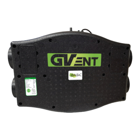
GV-INDUSTRIES HRVD125 User manual

VENTILADOR DESCENTRALIZADO
HRVD125
DECENTRALISED FAN
HRVD125
MANUFACTURED BY

Introdução
Aviso importante
Esquema geral
Operação e equipamento
Processo de montagem
Manutenção e limpeza
Descarte correto
Contactos
02
03
04
05
06
07
07
14
Introduction
Important warning
Operation and equipament
Mounting procedure
Maintenance and cleaning
Correct disposal
Contacts
08
08
10
10
11
12
14

Parabéns por ter adquirido um excelente recuperador de calor. Este recuperador dá a possibilidade
de limitar as perdas de calor, causadas pela ventilação da sala. A tarefa do recuperador é, portanto,
recuperar calor do ar de exaustão da sala em que está instalado. A unidade da série HRV está equipa-
da com um permutador de calor acumulado que retém e armazena a energia térmica para a transferir
para o ar fornecido do exterior. Graças a esta solução, é possível a troca de ar fresco com uma tem-
peratura próxima da temperatura prevalecente na sala.
Modo de extracção de ar
O recuperador HRV é sempre ligado em modo de exaustão. O ar retirado da sala após ser ligado
transfere energia térmica para o permutador de alumínio. Após sessenta segundos, o ventilador
muda automaticamente para o modo de alimentação.
Modo de alimentação de ar
O ar fornecido do exterior é aquecido pelo calor acumulado do permutador antes de entrar na sala.
Devido a tal acção, a perda de calor é imperceptível.
INTRODUÇÃO
Perigo! Risco de electrocussão
- alta voltagem!perigo
Atenção
elementos rotativos!
Por favor leia atentamente o Manual de utilização antes de tentar instalar ou reparar o dispositivo! A
Globovac não é responsável por qualquer dano resultante de operação incorreta, utilização não inten-
cional ou reparação não autorizada ou ainda modificações do produto.
O Manual de utilização contém informações técnicas importantes, instruções para o funcionamento e
segurança do dispositivo. Ler cuidadosamente as instruções de instalação no Manual de Operação.
Os seguintes simbolos mostram informações de segurança importantes para evitar ferimentos e perigo.
Precauções de segurança:
Este produto não deve ser manuseado por crianças com menos de 8 anos, idosos, por pessoas com defi-
ciências físicas e/ou mentais e por pessoas sem qualquer experiência ou compreensão do funcionamen-
to do produto. O seu manuseamento é então aconselhado se supervisionado ou instruído por um
adulto competente, para que compreendam os riscos operacionais relevantes. Este produto não é um
brinquedo e as crianças não devem brincar com ele. Não deve ser permitida a limpeza ou manutenção
do produto sem a supervisão de uma pessoa autorizada.
O dispositivo destina-se à instalação e ligação permanente com o sistema eléctrico do edifício.
O sistema eléctrico do edifício ligado ao ventilador deve ser capaz de quebrar o contacto de tensão sob
tensão em todos os pólos de comutação para isolar completamente o ventilador da energia durante
condições de sobretensão de Categoria III, em conformidade com os regulamentos de engenharia eléc-
trica aplicáveis.
O dispositivo foi concebido para instalação a uma altura de pelo menos 2,3 m acima do chão. O venti-
lador só deve ser instalado numa posição e com uma orientação especificada no Manual de utilização,
devido a necessidade de entrada do cabo de alimentação na caixa do ventilador.
AVISO IMPORTANTE
2

- Antes de efectuar a manutenção do dispositivo, isole-o da tensão da rede com o disjuntor. Fixar o
disjuntor contra uma operação inadvertida.
-A concepção da instalação do ventilador deve impedir a inversão do fluxo de gases de combustão
para dentro da sala condutas e aparelhos operados com chamas abertas
- Nunca tente modificar ou alterar o dispositivo sem autorização.
- Antes de instalar o ventilador, verificar a capacidade de suporte de carga da subestrutura de insta-
lação. A instalação incorrecta e a sua fixação pode resultar em danos ou falhas do ventilador e riscos
para as pessoas próximas.
O dispositivo pode tornar-se perigoso se for mal utilizado ou instalado
por pessoal não treinado.
Âmbito de utilização e condições de trabalho
- O recuperador destina-se ao bombeamento de ar normal ou ar contendo alguma poeira
(o tamanho das partículas < 10 μm), com baixos níveis de agressão e humidade, num clima tempera-
do.
- O dispositivo deve ser usado apenas se estiver instalado permanentemente, dentro de um edifício
e o acesso ao cabo de alimentação limitado.
- A amplitude de temperatura a que trabalha o dispositivo: -20°C até 40°C.
- O dispositivo está em conformidade com o nível de protecção IPX4, classe de protecção eléctrica:
II.
- A ferramenta deve ser utilizada apenas de acordo com a sua finalidade prevista e de acordo com a
marcação na placa de classificação.
- O ventilador deve ser ligado com o sistema de cabos eléctricos.
- O recuperador não pode ser utilizado com o objectivo de bombear ar contendo:
* contaminantes viscosos, que podem assentar no dispositivo,
* contaminantes cáusticos, que podem ter uma influência adversa no dispositivo,
* contaminantes de misturas de substâncias combustíveis sob a forma de gases, vapores,
névoas e poeiras, quando misturados com o ar, podem formar uma atmosfera explosiva.
- O dispositivo deve ser montado de forma a se desviar 2-5° da posição horizontal em direcção ao
exterior. É proibido montar o dispositivo em posição vertical (no tecto, no telhado).
Transporte e armazenamento
- O dispositivo deve ser armazenado numa embalagem original, num local seco e protegido contra a
precipitação.
- A temperatura no local de armazenamento e transporte deve ser mantida entre -20°C e +40°C.
- Evitar pancadas e choques. Os ventiladores devem ser transportados numa embalagem original.
- A eliminação deve ser efectuada de forma adequada e ecológica, em conformidade com as
disposições legais.
- Os danos causados por um transporte, armazenamento ou activação indevidos devem ser demon-
strados e não são sujeito a garantia.
- O sistema de controlo pode não permitir trabalhos extremos, incluindo activações e paragens
frequentes.
- O dispositivo deve ser montado numa divisória / parede externa, a uma distância adequada das
fontes de contaminantes (chaminés, gases de combustão, etc.) para que o ar esgotado/fornecido
esteja livre de contaminantes.
3

12
3
4
6
7
5
LN
N
L
min.335 max.540
103
25 86
160
160 190
190
25,5 86
min.335 max.540
128
200
200 190
190
Fig. 2
Fig. 3
Fig. 1
Fig. 4
4

Apenas pessoal formado pode, de acordo com as disposições aplicáveis, montar, ligar
para alimentar e activar o ventilador!
Descrição da operação:
O recuperador HRV está equipado com permutador de calor de regeneração de alumínio. A recu-
peração do calor perdido durante o processo de ventilação é possível devido ao trabalho de
direcção duplex do ventilador. O dispositivo funciona alternadamente:
- Ciclo de exaustão (o calor do fluxo do ar de exaustão é acumulado no permutador),
- Ciclo de fornecimento (o calor acumulado no permutador é emitido para o fluxo de ar fornecido).
O tempo de cada ciclo é de 60 s.
Os dispositivos HRV estão equipados com motores com duas velocidades de rotação. A mudança de
direcção do ar a transmitir é automático.
O ventilador é ativado com um interruptor separado que constitui um elemento do sistema de
cablagem eléctrica de um edifício (não é um elemento do dispositivo). A mudança da velocidade de
rotação tem lugar alternadamente, após puxos subsequentes do interruptor.
Remoto (índice terminado com a letra "P"). Os modelos equipados com um comando à distância
devem ser ligados em de acordo com o esquema de ligação na Fig. 3.
O ventilador é activado com o botão no comando à distância (Fig. 1). A alteração da velocidade de
rotação tem lugar directamente após premir o botão adequado no comando à distância. Depois de
ligar e desligar o dispositivo funciona com base na engrenagem que foi ajustada da última vez.
Os elementos básicos do dispositivo:
1. Ventilador de escape de duas velocidades.
2. Permutador de calor de acumulação de alumínio.
3. Permutador de ar.
4. Secção telescópica da conduta de ar, ajustável: 335 - 540 mm.
5. Fim da conduta de ar.
6. Controlo remoto
MIN
39 db
50m³/h
3W
MAX
42db
70m³/h
4,5W
Com comando
5

- Especificar exactamente o local, onde o dispositivo deve ser instalado.
- Preparar o cabo de alimentação de energia. Utilizar cabo elétrico 1.5mm
CUIDADO: Antes de iniciar as obras, deve certificar-se de que o cabo de alimentação não está em
tensão.
- Medir e criar uma abertura numa parede externa para a conduta telescópica do aparelho.
CUIDADO: O diâmetro da abertura deve ser pelo menos 10 mm maior em comparação com o exterior
diâmetro da conduta.
- Colocar a conduta telescópica (4) juntamente com o permutador (7) e o filtro (6) na parede externa e
selar com espuma ou algodão em lã.
A conduta deve ser montada de tal forma para que fique ligeiramente inclinada para o exterior. O
permutador juntamente com o filtro deve estar localizado a pelo menos 10 cm de distância da extremi-
dade da conduta telescópica.
- Inserir a extremidade da conduta (5) na conduta telescópica e depois fixá-la à parede com a utilização
de parafusos.
- Retirar o painel frontal do ventilador (1) e a tampa da electrónica (2).
- Arrastar o cabo eléctrico com duplo isolamento através da argola do cabo. Deslocar o cabo até que
seja possível ligá-lo a pinças de alimentação. Antes de fixar o ventilador: remover os objectos estranhos
do interior do ventilador; verificar, se o rotor gira livremente, fazendo-o mover-se com a mão.
- Insira o ventilador (3) na conduta telescópica e fixe-o à parede com o uso de parafusos.
CUIDADO: A argola do cabo deve ser colocada na parte inferior.
- Remover o isolamento externo do cabo, remover o isolamento dos fios com mais de 4 mm.
- Colocar o cabo e ligá-lo de acordo com o esquema de ligações do modelo instalado.
- Verificar se os condutores do cabo estão fortemente ligados às abraçadeiras.
- Verificar se o ventilador está fixado de forma sólida e se o sistema de cablagem eléctrica é adequado.
- Colocar e aparafusar a tampa electrónica (2).
- Verificar a vedação do cabo de ligação.
- O cabo de ligação deve ser fixado de forma a garantir que, em caso de inundação, não haja passagem
de água para as partes eléctricas.
- Montar o painel frontal (1) que constitui a protecção contra o contacto com as partes móveis.
ATENÇÃO! A hélice rotativa pode esmagar os seus dedos! É proibido ligar o ventilador
sem uma malha de protecção para as partes móveis!
A activação só pode ter lugar depois de todas as instruções de segurança terem sido verificadas e todos
os perigos terem sido eliminados. Após a activação, verificar se o ventilador funciona normalmente e de
forma adequada. Observar o trabalho do ventilador (o seu ruído, vibrações, consumo de electricidade, a
possibilidade de controlar a velocidade rotacional). O dispositivo só pode ser utilizado com o painel
frontal e a extremidade da conduta que constitui a protecção contra o contacto com as partes móveis.
O utilizador é responsável pelo cumprimento das presentes normas e pode suportar a responsabilidade
pelos acidentes resultantes da falta de elementos de protecção.
Ligação à rede eléctrica
- Apenas electricistas qualificados podem ligar o ventilador à fonte de alimentação e activá-lo durante o
primeiro tempo.
- As normas adequadas, disposições de segurança e condições técnicas para as ligações fornecidas pela
empresa de electricidade devem ser rigorosamente seguidas!
- Neste caso, é necessário utilizar um interruptor multipolar/isolador de rede com uma abertura mínima
de 3 mm de um contacto.
- Os tipos de rede, tensão e frequências têm de estar em conformidade com os dados da placa de classi-
ficação.
Dimensões.
As dimensões de modelos particulares foram apresentadas na figura 4
6
PT - PROCESSO DE MONTAGEM

Com a manutenção vai dar maior durabilidade e longividade ao produto.
- Durante a manutenção, deve usar sapatos e luvas de protecção!
- Durante todos os trabalhos de manutenção, cumprir as normas de segurança.
- As condutas de ar do ventilador têm de estar livres de objectos estranhos - perigo causado pelos
objectos deitados fora!
- Não efectuar a manutenção, quando o ventilador estiver a funcionar!
- Se conseguir sentir ou ouvir vibrações excessivas, deverá contratar um electricista autorizado para
realizar uma inspecção técnica do produto.
- Os períodos entre as inspecções técnicas dependem do nível de sujidade do motor e filtro, recomen-
da-se a sua limpeza de 6 em 6 meses.
- Verificar o motor quanto a fissuras.
- O fabricante não deve assumir qualquer responsabilidade pelos danos resultantes de uma reparação.
- No dispositivo, foram utilizados motores equipados com rolamentos de esferas "lubrificados durante
todo o período de utilizar" o motor não necessita de lubrificação.
Limpar o painel frontal e as partes visíveis do invólucro com pano húmido.
- Não utilizar substâncias agressivas que dissolvam o verniz!
- É proibido o uso de lavador de pressão ou jacto de água!
- Durante a limpeza, deve-se evitar que a água entre no interior do motor eléctrico ou da caixa de
derivação.
- A limpeza das grelhas na entrada/saída do ventilador deve ser mantida de forma contínua.
- No caso do filtro ficar sujo, a ventoinha deve ser desmontada, removida e depois o filtro deve
ser lavado com água corrente.
- Secar o filtro antes de a colocar novamente no interior.
1. O período de garantia para o bom funcionamento do dispositivo é de 2 anos, a partir da data de
venda.
2. Os direitos e obrigações da garantia serão nulos se não apresentar prova de compra.
(um recibo ou uma factura).
3. A garantia cobre todos os defeitos e danos atribuídos ao fabricante.
4. Faça com que o seu produto seja entregue para serviço de garantia ao fabricante ou ao vendedor
original.
5. A garantia não cobre nenhum dos seguintes: danos ao produto atribuíveis a danos impróprios ou
instalação sem restrições, operação contra a utilização pretendida, transporte, armazenamento e/ou
manutenção, quaisquer falhas atribuíveis a reparações não autorizadas, ou quaisquer danos acidentais.
6. A garantia não cobre a instalação ou a manutenção do produto.
No caso de danificar o isolamento, existe um risco de eletrocussão!
Antes de iniciar a limpeza, desligue completamente o ventilador da rede eléctrica .
PT - DESCARTE CORRETO
Não elimine os resíduos de equipamento eléctrico com resíduos domésticos.
O símbolo do caixote do lixo riscado neste produto significa que se trata de desperdício
de equipamento eléctrico e equipamentos electrónicos no fim da sua vida útil e não
devem ser eliminados com resíduos domésticos. O produto é fabricado a partir de
materiais e componentes recicláveis. Procure um contentor de produtos eletrónicos
para fazer o descarte correto.
7

Congratulations on your purchase of an excellent heat recuperator. The heat recuperator gives you
the possibility to limit the heat losses caused by the ventilation of the room. The task of the stove is
therefore to recover heat from the exhaust air of the room in which it is installed. The HRV series
unit is equipped with an accumulated heat exchanger that retains and stores heat energy to transfer
it to the air supplied from outside. Thanks to this solution, the exchange of fresh air at a temperature
close to the prevailing room temperature is possible.
Air extraction mode
The HRV stove is always switched on in exhaust mode. The air taken from the room after it is
switched on transfers thermal energy to the aluminum exchanger. After sixty seconds, the fan auto-
matically switches to supply mode.
Supply Air Mode
The air supplied from outside is heated by the heat accumulated in the exchanger before entering
the room. Due to such action, the heat loss is imperceptible.
Danger! Risk of Electrocution
- high voltage!danger
Attention
rotating elements!
Please read the Operation Manual carefully before attempting to install or repair the device! Globovac
is not responsible for any damage resulting from incorrect operation, unintended or unauthorized use,
repair or modification of the product.
The Operating Manual contains important technical information and instructions for the safe operation
of the device. Please read the installation instructions in the Operation Manual carefully.
The following symbols show important safety information to avoid injury and danger.
Safety Precautions:
This product not be used by children at least 8 years old elderly, by persons with physical and/or
mental disabilities and by persons without any experience in or understanding of the operation of the
product, if supervised or instructed by an adult competent in the safe use of the product so that they
understand the relevant operational risks. This product is not a toy and children should not play with
it. Children should not be allowed to clean or service the product without adult supervision.
The device is intended for permanent installation and connection with the building electrical system.
The building electrical system connected to the fan must be capable of breaking live voltage contact
on all switching poles to fully isolate the fan from power during Category III overvoltage conditions,
in accordance to applicable electrical engineering regulations.
The device is designed for installation at a height of at least 2.3 m above the floor. The fan should only
be installed in a position and orientation specified in the User Manual, due to the need for the power
cable to enter the fan casing.
EN -IMPORTANT WARNING
8

- Before servicing the device, isolate it from the mains voltage with the circuit breaker. Secure the
circuit breaker against inadvertent operation.
-The design of the fan installation must prevent reverse flow of flue gas into the room ducts and
appliances operated with open flames
- Never attempt to modify or alter the device without authorization.
- Before installing the fan, check the load-bearing capacity of the installation substructure. Incorrect
installation and securing can result in damage or failure of the fan and hazards to nearby persons.
The device can become dangerous if misused or installed
by untrained personnel.
Scope of use and working conditions
- The recuperator is intended for pumping normal air or air containing some dust
(the particle size < 10 μm), with low levels of aggression and humidity, in a temperate climate.
- The device can only be used if permanently installed, inside a building and if there is no access to
power the power cable is secured.
- Acceptable working temperature range of the device: from -20°C to +40°C.
- The device complies with protection level IPX4, electrical protection class: II.
- The tool must be used only in accordance with its intended purpose and in accordance with the
marking on the rating plate.
- The fan must be connected with the electric cable system.
- The recuperator may not be used for the purpose of pumping air containing
*viscous contaminants, which may settle on the device,
*caustic contaminants, which can have an adverse inuence on the device,
*contaminants from mixtures of combustible substances in the form of gases, vapors, mists
and dusts, which mixed with air, can form an explosive atmosphere.
- The control system may not allow extreme work, including frequent starts and stops.
- The device must be mounted on an external partition / wall, at a suitable distance from sources of
contaminants (chimneys, ue gases, etc.) so that the exhausted/supplied air is free of contaminants.
- The control system may not allow extreme work, including frequent starts and stops.
- The device must be mounted on an external partition / wall, at a suitable distance from sources of
contaminants (chimneys, ue gases, etc.) so that the exhausted/supplied air is free of contaminants.
- The device should be mounted in such a way that it moves 2-5° from the horizontal position towards
the outside. It is forbidden to mount the device in a vertical position (on the ceiling, on the roof).
Transport and Storage
- The device should be stored in its original packaging in a dry place, protected from precipitation.
- The temperature in the storage and transport location must be kept between -20°C and +40°C.
- Avoid knocks and surges. Fans must be transported in original packaging.
- Disposal must be carried out in a proper and environmentally friendly manner in accordance with
legal provisions.
- Damage caused by improper transport, storage or activation must be demonstrated and is not
subject to warranty.
9

DESCRIPTION OF OPERATION AND EQUIPMENT
Description of operation:
The HRV recuperator is equipped with aluminum regeneration heat exchanger. Recovery of heat lost
during the ventilation process is possible due to the duplex steering work of the fan. The device works
alternately:
- Exhaust cycle (heat from the exhaust air flow is accumulated in the exchanger),
- Supply cycle (heat accumulated in the exchanger is emitted into the supply air stream).
The time for each cycle is 60 s.
HRV devices are equipped with motors with two speeds of rotation. The change of direction of the air to
be transmitted is automatic.
The fan is activated with a separate switch that is an element of the electrical wiring system of a building
(it is and not an element of the device). The change of rotation speed takes place alternately, after subse-
quent pulls of the pull switch.
Remote (index ending with the letter "P"). Models equipped with a remote control must be connected in
accordance with the wiring diagram in Fig. 3.
The fan is activated with the button on the remote control (Fig. 1). Changing the rotation speed takes
place directly after pressing the appropriate button on the remote control. After switching on and off
again the device operates on the basis of the gear that was adjusted last time.
CONSTRUCTION AND ASSEMBLY
The basic elements of the device:
1. Two-speed exhaust fan.
2. Aluminum storage heat exchanger.
3. Air exchanger.
4. Telescopic air duct section, adjustable: 335 - 540 mm.
5. End of the air duct.
6. Remote control
Apenas pessoal formado pode, de acordo com as disposições aplicáveis, montar, ligar
para alimentar e activar o ventilador!
- Specify exactly the location, where the device is to be installed.
- Prepare the power supply cable. Use 1.5mm power cable
CAUTION: Before starting the work, you should make sure that the power cable is not live.
- Measure and create an opening in an external wall for the telescopic duct of the device.
CAUTION: The diameter of the opening must be at least 10 mm larger than the outside diameter of
the duct.
- Place the telescopic duct (4) together with the exchanger (7) and the filter (6) in the external wall
and seal with foam or absorbent cotton.
The duct must be mounted in such a way that it is slightly undone towards the outside. The exchang-
er together with the lintel must be located at least 10 cm away from the end of the telescopic duct.
- Insert the end of the duct (5) into the telescopic duct and then fasten it to the wall using assembly
pins.
- Remove the fan front panel (1) and the electronics cover (2).
- Drag the double insulated power cable through the cable lug. Move the cable until it is possible to
connect it to power clamps. 10

WARNING! A rotating propeller can crush your fingers! It is forbidden to start the
fan without a protective mesh against touching the moving parts!
Activation may only take place after all safety instructions have been checked and all hazards have
been eliminated. After activation, check that the fan operates normally and that the airflow is
adequate.
Observe the work of the fan (its noise, vibrations, electricity consumption, the possibility to con-
trol the rotational speed).
The device may only be used with the front panel and the end of the duct that is the protection
against contact with moving parts. The user is responsible for compliance with these regulations
and can bear the responsibility for accidents resulting from the lack of protection elements.
Connection to the mains
- Only qualified electricians may connect the fan to the mains supply and activate it during the first
time.
- The appropriate regulations, safety provisions and technical conditions for company connections
The power supply must be strictly followed!
- In this case a multi-pole switch/mainswitch with a minimum opening of 3 mm of a
contact.
- Mains types, voltages and frequencies must comply with the data on the rating plate.
Dimensions.
The dimensions of particular models are shown in the figures: 4
11
With maintenance you will give the product greater durability and long life.
- During maintenance wear protective shoes and gloves!
- During all maintenance work observe the safety regulations.
- The air ducts of the fan must be free of foreign objects - danger caused by thrown-away objects!
- Do not carry out maintenance when the fan is running!
- If you can feel or hear excessive vibrations you should hire an authorized electrician to carry out a
technical inspection of the product.
- The periods between technical inspections depend on the level of dirtiness of the motor and filter,
it is recommended to clean them every 6 months.
- Check the motor for cracks.
- The manufacturer shall not assume any liability for damage resulting from a repair.
- In the device, motors equipped with ball bearings "lubricated for the entire period of use" were
used the motor does not require lubrication.
In case of damage to the insulation, there is a risk of electrocution!
Before starting cleaning, completely disconnect the fan from the primary
energy source.
EN - MAINTENANCE AND CLEANING
Clean the front panel and the visible parts of the housing with a damp cloth.
- Do not use aggressive substances that dissolve the varnish!
- The use of pressure washer or water jet is forbidden!
- During cleaning, it must be prevented that water gets inside the electric motor or the junction
box.

- The cleaning of the grids at the fan inlet/outlet must be maintained continuously.
- In case the filter gets dirty, the fan should be disassembled, removed and then the filter washed
under running water.
be washed under running water.
- Dry the filter before putting it back inside.
WARRANTY TERMS & CONDITIONS
1. The warranty period for the proper functioning of the device is 2 years from the date of sale.
2. Warranty rights and obligations will be void if you do not provide proof of purchase
(a receipt or an invoice).
3. The warranty covers all defects and damages attributable to the manufacturer.
4. Have your product delivered for warranty service to the original manufacturer or seller.
5. The warranty does not cover any of the following: damage to the product attributable to
improper damage or
unrestricted installation, operation against its intended use, transportation, storage and/or
maintenance, any failures attributable to unauthorized repairs, or any accidental damage.
6. The warranty does not cover installation or maintenance of the product.
7. The warranty does not cover installation or maintenance of the product.
EN - CORRECT DISPOSAL
Do not dispose of waste electrical equipment with household waste.
The crossed out dustbin symbol on this product means that it is waste electrical and
electronic equipment at the end of its life and should not be disposed of with house-
hold waste. The product is made from recyclable materials and components. Look for
an electronics container to dispose of it properly.
12

Desencaixar a tampa frontal, limpe a hélice da ventoinha, não deixar humida ou molhada.
Detach the front cover, clean the fan impeller, do not leave it wet or damp.
Retire o permutador que se encontra dento do tubo telescópico e lavar com água corrente,
deixar secar por completo ao sol.
Limpar a grelha exterior
não deixar molhada.
Clean the outer grid
do not leave it wet.
Remove the exchanger inside the telescopic tube and wash it under running water,
allow to dry completely in the sun.
13

www.globovac.net
Email: [email protected]
Telefone: +351 239 088 948 (Rede Fixa Nacional)
Fax: +351 239 088 949 (Rede Fixa Nacional)
Telemóvel: +351 917 239 002 (Rede Móvel Nacional)
Morada: Rua da Cerca, Urbanização Madefil, Armazém 10B,
Sargento-Mor, 3020-832 Souselas, PORTUGAL
www.globovac.com
Email: [email protected]
Tel Export: +44 (0) 1823 665 777
+44 (0) 1293 772 165
Mobile: +44 (0) 1293 665 175
Globovac Ltd, 8C Castle Road, Chelston Business Park,
Wellington, Somerset, TA21 9JQ, UNITED KINGDOM
Ventilador desentralizado-2023_v1
PT-CONTACTOS | EN-CONTACTS
14
Table of contents
Languages:
Other GV-INDUSTRIES Fan manuals
Popular Fan manuals by other brands

Hunter
Hunter 23483 Parts guide

Dometic
Dometic FanTastic Vent Series Installation and operating manual

aldes
aldes TAHA Series Assembly instruction

DYNABREEZE
DYNABREEZE FA-23099 Instructions & user's manual

MTD
MTD MTD-ERV 350 Installation & operating manual

Lasko
Lasko S18902 Important instructions & operating manual

Colasit
Colasit CMVpro 125-400 ATEX operating instructions

Singer
Singer SFR40-5 BL instruction manual

Spirax Sarco
Spirax Sarco AVM7 Installation and maintenance instructions

Broan
Broan ssQTXe080 instructions

Lampenwelt
Lampenwelt 4018211 Mounting instructions

NuAire
NuAire MEV-DC2 Installation and Maintenance