MOVEHEAD FIXTURE USER MANUAL
Page 6
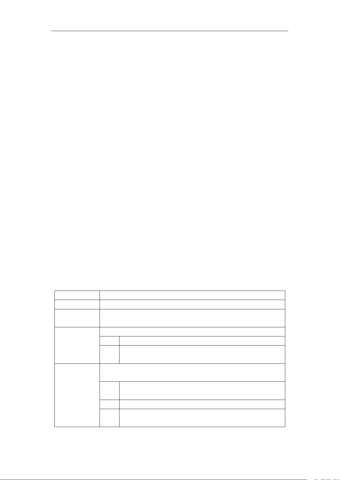
Figure 6 Parameter menu
3. Operation and parameter instruction
Chick item of main menu, enter corresponding sub menu shown in Figure 6, In main menu, chick
1/6 function button into corresponding parameter menu.
In sub menu(page), chick main item on the left side of display, can shift to corresponding sub
menu(page) quickly.
1. DMX Address setting
Enter page show in Figure6-1, can set fixture DMX address, channel mode and so on.
The menu settings of fixture have optimized the setting of addresses. Several settings of the
address are as follows:
Select " Prev " or "Next", the fixture will be based on the current address and channel mode,
automatically calculate the next or last address, make address setting can quickly;
Click on the address value, you can enter the numeric editing window, where you can set any
valid address, fixture system automatically get the current number of channels, automatically
filter the unusable address (512 - the current number of channels).
Fixture support RDM protocol, remote address can be set through RDM.
Provide one buttons:
Channel mode: you can choose different channel modes by cycle.
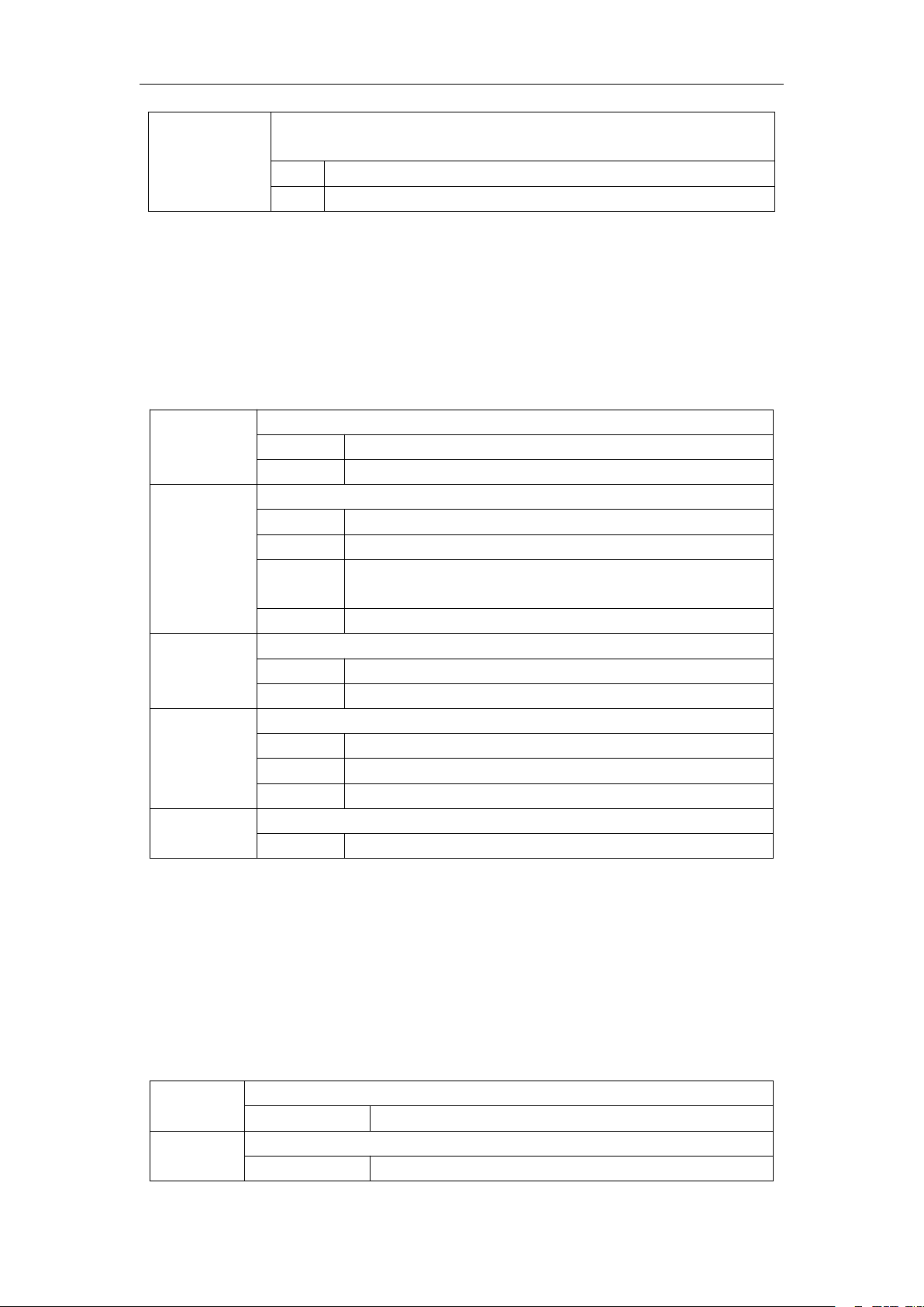
2. Fixture operating mode setting
Through the page shown in Figure 6-2, the operating mode of the fixture can be set and the lamp
can be controlled. The fixture supports four operating modes (DMX mode, auto mode, voice
control mode and scene mode). Detailed parameter settings can be refer in the previous section.
Specific parameter descriptions are as follows:
operating mode
DMX mode, receive DMX signal, RDM signal
Fixture run automatically according to built-in programs
When the fixture detects a strong sound, the fixture automatically runs a scene
according to the built-in program, otherwise it will stay the last scene
runs in a set scene, which supports most of the custom editing of 10 scenes.
outputs the specified scene
Automatically loops the output scene in the set scene time (non-zero) order,
and the scene with time 0 automatically ignore
Master and slave selection, non-DMX mode takes effect, select the mode of data
output, fixture detect DMX cable state automatic switch output, prevent data conflicts
fixture runs built-in program. If DMX has no signal, it outputs data
(synchronization), otherwise it does not output data.
fixture runs built-in program and do not output data
If DMX has no signal, the fixture will runs built-in program. Otherwise, the
fixture will run in DMX Mode(follow DMX).