H-BUSTER HBTV-32D02FD User manual

Service Manual
1
CONTENTS
Chapter 1.General Information
1-1. General Guidelines
................................................................................. 3
1-2. Important Notice...................................................................................... 3
1-2-1. Follow the regulations and warnings...................................................... 3
1-2-2. Be careful to the electrical shock
1-2-3. Electro static discharge
1-2-4. About lead free solder (PbF)
1-2-5. Use the genewing parts (specified parts) .............................................. 4
1-2-6. Safety check after repairment................................................................ 4
1-2-7. Ordering Spare Parts............................................................................. 6
1-2-8. Photo used in this manual ..................................................................... 6
1-3. How to Read this Service Manual
...................................................... 6
1-3-1. Using icons: ........................................................................................... 6
Chapter 2. Specification
2-1. Specification list ......................................................................................7
2-2. External pictures (four faces) ..............................................................7
Chapter 3. Disassemble and Assemble
Chapter 4. Location of Controls and Components
4-1. Board Location.......................................................................................17
4-2. Main Board & AV Board.......................................................................18
4-2-1. Function Description.............................................................................
4-2-2. Connector definition.............................................................................
4-3. Power Supply Board.............................................................................
4-3-1. Function description.............................................................................
4-3-2. Connector definition..............................................................................
4-4. LCD Panel ..............................................................................................22
4-4-1. Function Description: Display the signal...............................................
4-4-2. Connector definition..............................................................................
4
-
HBTV-32D02 / 40D02
.............................................................................
13
....................................................................
15
3-1. HBTV-32D02FD
3-2. HBTV-40D02FD
........................................................... 3
.......................................................................... 3
.................................................................. 4
Chapter 5. Operation Instructions
5-1. Get To KnowYour TV......................................................................... 26
5-2. Get To KnowYour Remote Control
................................................. 28
C
5-
5
5
20
20
20
22
22
18
18

Service Manual
HBTV-32D02 / 40D02
2
Chapter 6. Electrical Parts
.......................................................................................29
.......................................................................................30
7-1. Service Mode (Modo de Serviço) .......................................................46
7-1-1.Howto enter into Service Mode (como entrar no modo de serviço) .......46
7-1-2.Howto exit (sair do modo de serviço) .....................................................46
7-2. Measurements and Adjustments ........................................................ 46
7-2-1. Memory Resetting (Reinicializando a memória) . ......................................46
Chapter 9. Troubleshooting(guia de defeitos)
9-1. Power Supply Board Failure Check...................................................50
C
6---1. Block Diagram
6-2. Circuit Diagram
7-
7-
C
9 -
Chapter 7. Measurements and Adjustments
Chapter 8. Firmware Update (Atualização de Programa)
7-1. Initial Care (Cuidados Iniciais)
7-2. Initial Procedures (Procedimentos Iniciais)
.Updating firmware (Atualizando o programa)................................. 48
C
8-
8-
8-3
.......................................47
Chapter 10. Exploded View and Parts List
...................................................................................52
....................................................................................54
C
10-1. HBTV-32D02FD
10-2. HBTV-40D02FD
...........................................................47
.Firmware Update Diagram (Diagrama da Atualização do programa)
49
8-4
..................................................................................................................
Service Manual
3
HBTV-32D02 / 40D02
Chapter 1.General Information
1-1. General Guidelines
When servicing, observe the original lead dress. If a short circuit is found, replace all parts which
have been overheated or damaged by the short circuit.
After servicing, see to it that all the protective devices such as insulation barriers, insulation papers
shields are properly installed.
After servicing, make the following leakage current checks to prevent the customer from being
exposed to shock hazards.
1) Leakage Current Cold Check
2) Leakage Current Hot Check
3) Prevention of Electro Static Discharge (ESD) to Electrostatically Sensitive
1-2. Important Notice
1-2-1. Follow the regulations and warnings
Most important thing is to list up the potential hazard or risk for the service personnel to open
the units and disassemble the units. For example, we need to describe properly how to avoid the
possibility to get electrical shock from the live power supply or charged electrical parts (even the
power is off).
This symbol indicates that high voltage is present inside.It is dangerous to make any
kind of contact with any inside part of this product.
This symbol indicates that there are important operating and maintenance instructions
in the literture accompanying the appliance.
1-2-2. Be careful to the electrical shock
To prevent damage which might result in electric shock or fire, do not expose this TV set to
rain or excessive moisture. This TV must not be exposed to dripping or splashing water, and
objects filled with liquid, such as vases, must not be placed on top of or above the TV.
1-2-3. Electro static discharge (ESD)
Some semiconductor (solid state) devices can be damaged easily by static electricity.
Such components commonly are called Electrostatically Sensitive (ES) Devices. The following
techniques should be used to help reduce the incidence of component damage caused by
electros static discharge (ESD).

Service Manual
4
Electrostatically Sensitive (ES) Devices
Some semiconductor (solid-state) devices can be damaged easily by static electricity. Such
components commonly are called Electrostatically Sensitive (ES) Devices. Examples of typical
ES devices are integrated circuits and some field-effect transistors and semiconductor "chip"
components. The following techniques should be used to help reduce the ncidence of component
damage caused by static by static electricity.
1. Immediately before handling any semiconductor component or semiconductor-equipped
assembly, drain off any electrostatic charge on your body by touching a known earth ground.
Alternatively, obtain and wear a commercially available discharging wrist strap device, which
should be removed to prevent potential shock reasons prior to applying power to the unit under
test.
2. After removing an electrical assembly equipped with ES devices, place the assembly on a
conductive surface such as aluminum foil, to prevent electrostatic charge buildup or exposure of
the assembly.
1-2-4. About lead free solder (PbF)
This product is manufactured using lead-free solder as a part of a movement within the
consumer products industry at large to be environmentally responsible. Lead-free solder must be
used in the servicing and repairing of this product.
1-2-5. Use the genewing parts (specified parts)
Special parts which have purposes of fire retardant (resistors), high-quality sound (capacitors),
low noise (resistors), etc. are used.
When replacing any of components, be sure to use only manufacture's specified parts shown in
the parts list.
Safety Component
●Components identified by mark have special characteristics important for safety.
1-2-6. Safety check after repairment
Confirm that the screws, parts and wiring which were removed in order to service are put in the
original positions, or whether there are the positions which are deteriorated around the serviced
places serviced or not. Check the insulation between the antenna terminal or external metal and
the AC cord plug blades. And be sure the safety of that.
General Servicing Precautions
1. Always unplug the receiver AC power cord from the AC power source before:
a. Removing or reinstalling any component, circuit board module or any other receiver
assembly.
HBTV-32D02 / 40D02

Service Manual
5
HBTV-32D02 / 40D02
b. Disconnecting or reconnecting any receiver electrical plug or other electrical connection.
c. Connecting a test substitute in parallel with an electrolytic capacitor in the receiver.
CAUTION: A wrong part substitution or incorrect polarity installation of electrolytic capacitors
may result in an explosion hazard.
2. Test high voltage only by measuring it with an appropriate high voltage meter or other voltage
measuring device (DVM, FETVOM, etc) equipped with a suitable high voltage probe.
Do not test high voltage by "drawing an arc".
3. Do not spray chemicals on or near this receiver or any of its assemblies.
4. Unless specified otherwise in this service manual, clean electrical contacts only by applying
the following mixture to the contacts with a pipe cleaner, cotton-tipped stick or comparable non-
abrasive applicator; 10% (by volume) Acetone and 90% (by volume) isopropyl alcohol (90%-99%
strength).
CAUTION: This is a flammable mixture.
Unless specified otherwise in this service manual, lubrication of contacts is not required.
Capacitors may result in an explosion hazard.
5. Do not defeat any plug/socket B+ voltage interlocks with which receivers covered by this
service manual might be equipped.
6. Do not apply AC power to this instrument and/or any of its electrical assemblies unless all
solid-state device heat sinks are correctly installed.
7. Always connect the test receiver ground lead to the receiver chassis ground before connecting
the test receiver positive lead.
Always remove the test receiver ground lead last. Capacitors may result in an explosion
hazard.
8. Use with this receiver only the test fixtures specified in this service manual.
CAUTION: Do not connect the test fixture ground strap to any heat sink in this receiver.
9. Remove the antenna terminal on TV and turn on the TV.
10. Insulation resistance between the cord plug terminals and the eternal exposure metal should
be more than Mohm by using the 500V insulation resistance meter.
11. If the insulation resistance is less than M ohm, the inspection repair should be required.
If you have not the 500V insulation resistance meter, use a Tester. External exposure metal:
Antenna terminal Headphone jack.

Service Manual
6
12. Use only a grounded-tip soldering iron to solder or unsolder ES devices.
13. Use only an anti-static type solder removal device. Some solder removal devices not
classified as "anti-static" can generate electrical charges sufficient to damage ES devices.
14. Do not use freon-propelled chemicals. These can generate electrical charges sufficient
to damage ES devices.
15. Do not remove a replacement ES device from its protective package until immedi-
ately before you are ready to install it.
(Most replacement ES devices are packaged with leads electrically shorted together by
conductive foam, aluminum foil or comparable conductive material).
16. Immediately before removing the protective material from the leads of a replacement ES
device, touch the protective material to the chassis or circuit assembly into which the device will
be installed.
CAUTION: Be sure no power is applied to the chassis or circuit, and observe all other safety
precautions.
17. Minimize bodily motions when handling unpackaged replacement ES devices. (Otherwise
harmless motion such as the brushing together of your clothes fabric or the lifting of your foot
from a carpeted floor can generate static electricity sufficient to damage an ES device.)
1-2-7. Ordering Spare Parts
Please include the following informations when you order parts. (Particularly the Version letter)
1. Model number, serial number and software version
The model number and serial number can be found on the back cover of each product. Software
version can be found in the Spare Parts List.
2. Spare part No. and description
Spare part No. and description can be found in the Spare Parts List.
1-2-8. Photo used in this manual
The illustration and photos used in this Service Manual may not base on the final design of
products, which may differ from your products in some way.
HBTV-32D02 / 40D02

Service Manual
7
HBTV-32D02 / 40D02
1-3. How to Read this Service Manual
1-3-1. Using icons:
Icons are used to attract the attention of the reader to specific information. The
meaning of each icon is described in the table below:
Note:
A “note” provides information that is not indispensable, but may nevertheless be
valuable to the reader, such as tips and tricks.
Caution:
A “caution” is used when there is danger that the reader, through incorrect
manipulation, may damage equipment, loose data, get an unexpected result or has to
restart(part of) a procedure.
Warning:
A “warning” is used when there is danger of personal injury.
Reference:
A “reference” guides the reader to other places in this binder or in this manual,
where he/she will find additional information on a specific topic.

Service Manual
8
Chapter 2. Specification
2-1. Specification list
0RGHO
6FUHHQVL]H
$VSHFW UDWLR
5HVROXWLRQ
5HVSRQVH7LPH˄PV
$QJHORIYLHZ
+9 +9
&RQWUDVW
%ULJKWQHVV
26'ODQJXDJH
(QJOLVK
3RUWXJXHVH
6SDQLVK
(QJOLVK
3RUWXJXHVH
6SDQLVK
&RORUV\VWHP
$XGLRV\VWHP
01 01
$XGLRRXWSXWSRZHU%XLOWLQ:
: :
7RWDOSRZHULQSXW˄:˅
9ROWDJHUDQJH˄9˅
3RZHUIUHTXHQF\˄+]˅
+= +=
1HWZHLJKW.*
*URVVZHLJKW.*
1HWGLPHQVLRQ00
ZLWKVWDQG ZLWKVWDQG˅
PAL NTSC ISDB-T PAL NTSC ISDB-T
ZLWKVWDQG
ZLWKVWDQG
ZLWKVWDQG
ZLWKVWDQG
LQFK LQFK
PV PV
FGPFGP
::
9 9
HBTV-32FD02 HBTV-40D02FD
HBTV-32D02 / 40D02

Service Manual
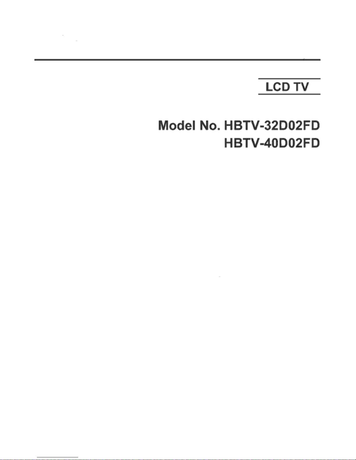
2-2. External pictures (four faces)
Front Side
Left Side
2-2-1. HBTV-32D02FD
9
HBTV-32D02 / 40D02
Service Manual
10
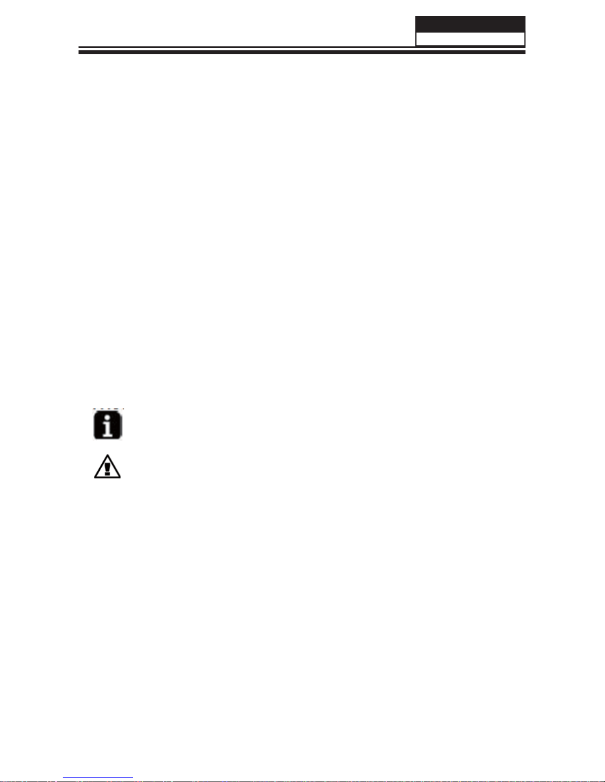
Right Side
Back Side
HBTV-32D02 / 40D02

Service Manual
Front Side
Left Side
2-2-2. HBTV-40D02FD
11
HBTV-32D02 / 40D02

Service Manual
12
Right Side
Back Side
HBTV-32D02 / 40D02

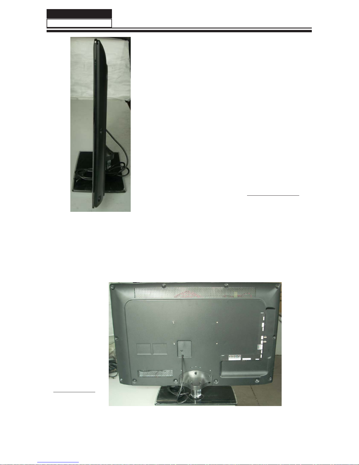
Chapter 3. Disassemble and Assemble
3-1. HBTV-32D02FD
3-1-2. Remove the Back Cover
Service Manual
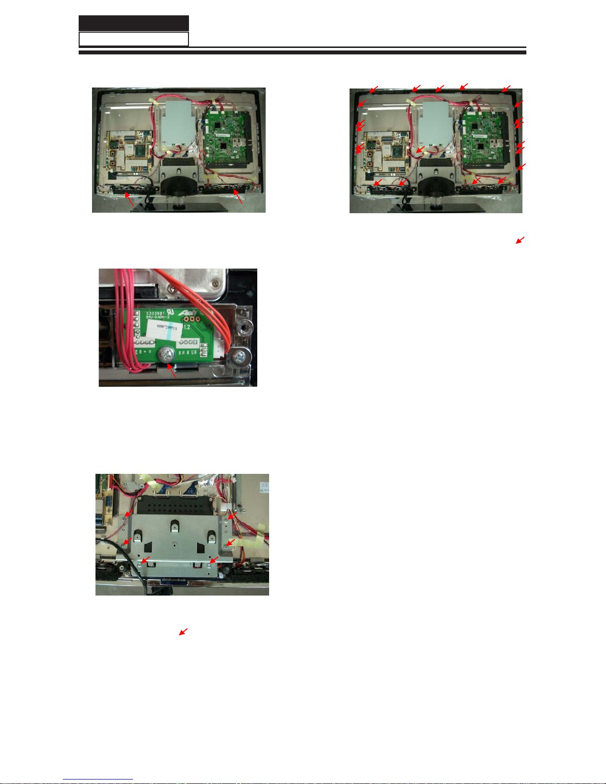
3-1-3. Remove the mainboard
power supply
3-1-1. Remove the Stand
3-1-4. Remove the
13
ķ/D\GRZQWKHXQLWVRWKDWUHDU
FRYHUIDFHVXSZDUG
ĸ5HPRYHWKHILYHVFUHZVIURPWKHUHDU
FRYHULQGLFDWHGZLWK
Ĺ7KHQUHPRYHWKHVWDQG
ķ5HPRYHWKHWZHQW\VFUHZVLQGLFDWHG
RQILJXUHDERYHE\
ĸ7KHQUHPRYHWKHEDFNFRYHUIURP
WKHXQLW
ķ5HPRYHWKHVL[VFUHZVLQGLFDWHGRQ
WKHILJXUHDERYHE\
ĸ5HPRYHWKH0HWDOWHUPLQDOERDUGDQG
ķ5HPRYHWKHIRXUVFUHZV
LQGLFDWHGRQWKHILJXUHDERYHE\
ĸ7KHQUHPRYHWKHSRZHUVXSSO\
0DLQERDUG
HBTV-32D02 / 40D02
3-1-6. Remove the remote control
3-1-8. Remove the Panel
Service Manual
14
3-1-5. Remove the Speaker
Takeoutthespeakerdirectly.
5HPRYHWKHVFUHZ
WDNHRXWWKHUHPRWHFRQWUROERDUG
ķ5HPRYHWKHWZHQW\RQHVFUHZV
LQGLFDWHGRQWKHILJXUHDERYHE\
ĸ5HPRYHWKH0HWDOSUHVVLQJVOLFH
3-1-7. Remove the Metal connecting
board
ķ5HPRYHWKHVL[VFUHZVLQGLFDWHGRQWKH
ILJXUHDERYHE\
ĸ5HPRYHWKH0HWDOFRQQHFWLQJERDUG
Ĺ7KHQUHPRYHWKH3DQHO
HBTV-32D02 / 40D02

3-2. HBTV-40D02FD
3-2-2. Remove the Back Cover
Service Manual
15
3-2-4. Remove the speaker
3-2-1. Remove the Stand
3-2-3. Remove the mainboard and
bracket of Side AV
ķ5HPRYHWKHWZHQW\WZRVFUHZVLQGLFDWHG
RQILJXUHDERYHE\
ĸ7KHQUHPRYHWKHEDFNFRYHUIURPWKH
XQLW
ķ5HPRYHWKHVHYHQVFUHZVLQGLFDWHGRQ
WKHILJXUHDERYHE\
ĸ5HPRYHWKH0DLQERDUG
ķ/D\GRZQWKHXQLWVRWKDWUHDU
FRYHUIDFHVXSZDUG
ĸ5HPRYHWKHILYHVFUHZVIURPWKHUHDU
FRYHULQGLFDWHGZLWK
Ĺ7KHQUHPRYHWKHVWDQG
HBTV-32D02 / 40D02

Service Manual
16
3-2-5. Remove the remote
5HPRYHWKHVFUHZ
WDNHRXWWKHUHPRWHFRQWUROERDUG
3-2-7. Remove the panel bracket
ķ5HPRYHWKHVL[VFUHZVLQGLFDWHGRQWKH
ILJXUHDERYHE\
ĸ5HPRYHWKH3DQHO%UDFNHWDQG0HWDO6OLFH
Ĺ7KHQ\RXFDQWDNHRIIWKH3DQHO
ķ5HPRYHWKHWZRVFUHZVLQGLFDWHG
RQWKHILJXUHDERYHE\
ĸ5HPRYHWKHVSHDNHU
control
3-2-6. Remove the Metal connecting
board
ķ5HPRYHWKHVL[VFUHZVLQGLFDWHGRQWKH
ILJXUHDERYHE\
ĸ5HPRYHWKH0HWDOFRQQHFWLQJERDUG
HBTV-32D02 / 40D02
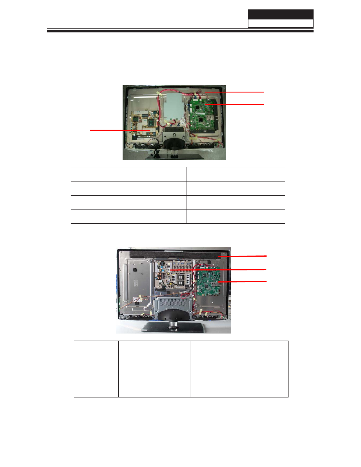
Chapter 4. Location of Controls and Components
4-1. Board Location
No. Parts number Description
4-1-2. HBTV-40D02FD
Service Manual
17
4-1-1. HBTV-32D02FD
A
B
C
Placa Principal
A Board
B Board Tela de LCD
C Board Placa da Fonte
No. Parts number Description
A Board
B Board
C Board
A
B
C
HBTV-32D02 / 40D02
Placa Principal
Tela de LCD
Placa da Fonte
(***)
497130
410226
410299
410396
410394
(***) - VERIFIQUE TABELA NO FINAL DO MANUAL (LISTA DE PEÇAS)
TODAS AS PEÇAS ACIMA SOMENTE SÃO LIBERADAS
MEDIANTE CONSULTA AO SUPORTE TÉCNICO!!!!
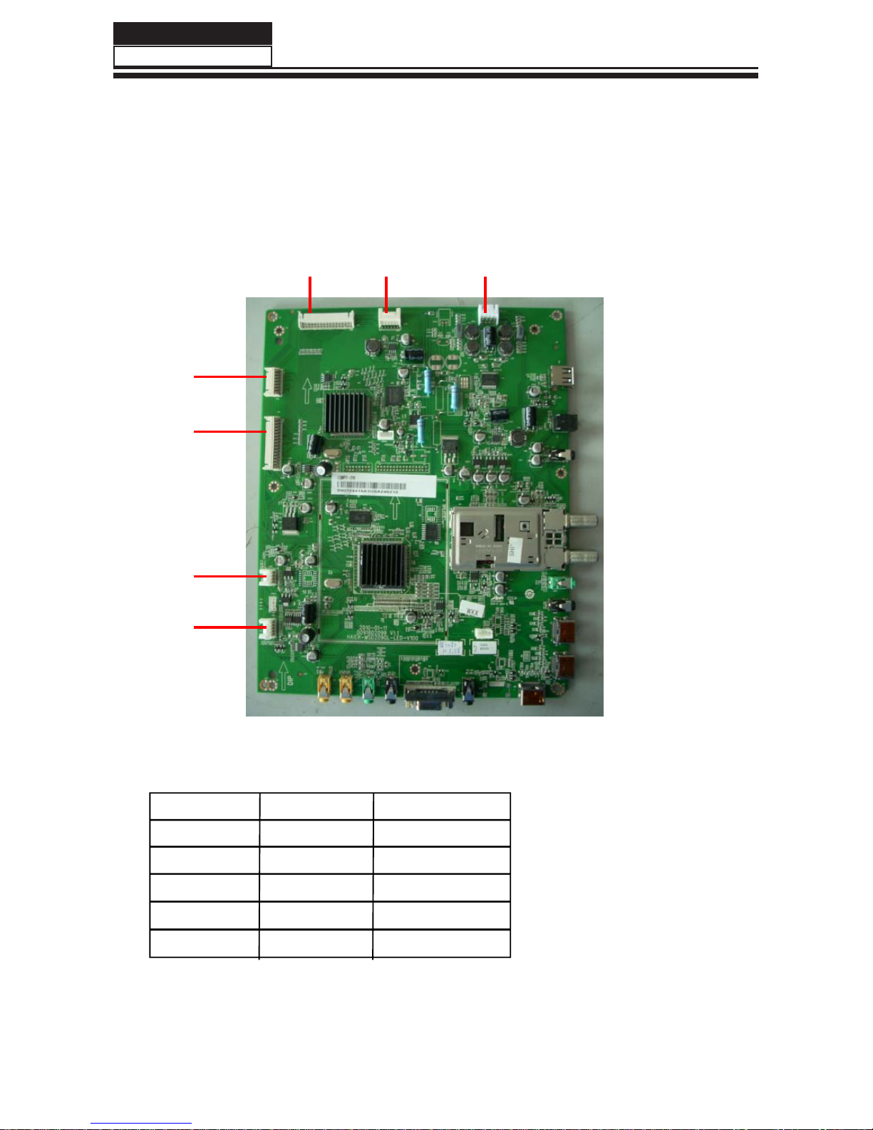
4-2.Mainboard
4-2-1. Function Description:
Process signal which incept from exterior equipment then translate into signal that panel can display.
4-2-2-1.Mainboard of HBTV-32D02FD / HBTV-40D02FD
4-2-2.Connector definition
CNB4
CNB3
CN5
CN2
CN4
Remote connectors (CNB4)
Pin number Signal name Description
5
5VSTB
IR IN
IR
LED_R
LED_B
GND GND
1
2
3
4
4-2-2-2.Connector definition
18
Service Manual
CN27
CN10
5V-Stand
LED-RED
LED-BLUE
HBTV-32D02 / 40D02

19
1
2
3
4
Key connectors (CNB3)
Pin number Signal name Description
KEY0
KEY1
3.3V
Speaker connectors (CN27)
1
2
3
Pin number Signal name Description
R-
L+
L-
4R+
Left of audio
Right of audio
Left of audio
Right of audio
1
2
3
Pin number Signal name Description
Service Manual
GND GND
KEY0
KEY1
3.3V
Power connectors (CN10)
4
5
6
7
8
9
10
11
12
12V 12V-Mainboard
12V
12V
GND GND
GND
GND
GND
GND
12V-Mainboard
12V-Mainboard
5VSTB 5V_standby
E-PWM ([WHUQDO3:0&RQWURO
GND GND
PW-ON/OFF Pow er on/off
NC NO Connection
PB-ON/OFF Back light on/off
HBTV-32D02 / 40D02
This manual suits for next models
1
Table of contents
Other H-BUSTER LCD TV manuals


