H-BUSTER HBTV-22D02FD User manual
LCD TV
MANUAL DE SERVIÇO
Model No.: HBTV-22D02FD
Este manual técnico é de uso exclusivo da Rede Autorizada H-Buster. Não existem peças ou partes que possam
ser reparados pelo consumidor final, sob riscos de choque elétrico, causando ferimentos graves.
É proibida a distribuição, comercialização ou cópia deste documento. Sujeito a modificações.
© 2011 H-BUSTER DO BRASIL
ATENÇÃO
Chassis: MTK5363
Service Manual
1
CONTENTS
Chapter 1. General Information
..............................................................................3
1-2. Important Notice...................................................................................3
1-3-1. Follow the regulations and warnings .....................................................3
1-3-2. Be careful to the electrical shock...........................................................3
1-3-3. Electro static discharge (ESD)...............................................................3
1-3-4. About lead free solder (PbF)..................................................................4
1-3-5. Use the genewing parts (specified parts) ..............................................4
1-3-6. Safety check after repairment................................................................4
1-3-7. Ordering Spare Parts.............................................................................6
1-3-8. Photo used in this manual .....................................................................6
1-3. How to Read this Service Manual..................................................7
1-3-1. Using icons: ...........................................................................................7
Chapter 2. Specification
2-1. Specification list...................................................................................8
2-2. External pictures (four faces)..........................................................9
Chapter 3. Disassemble and Assemble
3-1. Remove the Stand .............................................................................10
3-2. Remove the Back Cover..................................................................10
3-3. Remove the Main Board & Small Board .................................... 11
3-3-1. Remove the Mainboard and the Driver Board ..................................... 11
3-3-2. Remove the Remote Control Board..................................................... 11
3-3-3. Remove the Keypad Board ................................................................. 11
3-3-4. Remove the Speakers ......................................................................... 11
Chapter 4. Location of Controls and Components
4-1. Board Location...................................................................................12
4-2. Main Board ..........................................................................................12
4-2-1. Function Description.............................................................................13
4-2-2. Connector definition.............................................................................13
4-3. Driver Board.........................................................................................14
4-4. Remote Control Board
........................................................................14
4-5. LED Panel.............................................................................................14
1-1. General Guidelines
HBTV-22D02FD
Service Manual
2
Chapter 5. Operation Instructions
5-1. Front Panel Controls......................................................................... 15
5-2. BACK Panel Controls....................................................................... 15
Chapter 6. Electrical Circuit
7-1. Power Tree............................................................................................ 18
7-2. Wiring Connection Diagram........................................................... 18
7-3. Circuit Diagram...................................................................................19
8
7-1. Service Mode.......................................................................................
36
7-1-1.How to enter into Service Mode............................................................
............................................................................................
8
Chapter 9. Exploded View and Parts List
5
-
5
-
C
6
-
6
-
6
-
8-
C
HBTV-22D02FD
C
-3. Remote Control
5 ...................................................................................16
Chapter 7. Measures and Adjustments
C
7
7-1-2.How to exit
Chapter 8. Firmware Update (Atualização de Programa)
8-1. Initial Care (Cuidados Iniciais)
8-2. Initial Procedures (Procedimentos Iniciais).............................37
...................................................... 37
36
36
8-2-1. Needed tools (Ferramentas necessárias) .......................................... 37
8-2-2. How to identify the Panel Type (Como identificar o modelo de painel de LCD)
............................................................................................................ 37
8-2-3. Copying the firmware to USB Memory Key (copiando o programa no pen-
drive) ............................................................................................................ 38
8-3. Updating the firmware (Atualizando o programa).................. 38
8-4. Firmware Update Diagram (Diagramada atualização de programa)
..................................................................................................................39
9-1. Exploded View.....................................................................................41
9-2. Parts List...............................................................................................42

Service Manual
3
Chapter 1.General Information
1-1. General Guidelines
When servicing, observe the original lead dress. If a short circuit is found, replace all parts which
have been overheated or damaged by the short circuit.
After servicing, see to it that all the protective devices such as insulation barriers, insulation papers
shields are properly installed.
After servicing, make the following leakage current checks to prevent the customer from being
exposed to shock hazards.
1) Leakage Current Cold Check
2) Leakage Current Hot Check
3) Prevention of Electro Static Discharge (ESD) to Electrostatically Sensitive
1-2. Important Notice
1-2-1. Follow the regulations and warnings
Most important thing is to list up the potential hazard or risk for the service personnel to open
the units and disassemble the units. For example, we need to describe properly how to avoid the
possibility to get electrical shock from the live power supply or charged electrical parts (even the
power is off).
This symbol indicates that high voltage is present inside.It is dangerous to make any
kind of contact with any inside part of this product.
This symbol indicates that there are important operating and maintenance instructions
in the literture accompanying the appliance.
1-2-2. Be careful to the electrical shock
To prevent damage which might result in electric shock or fire, do not expose this TV set to
rain or excessive moisture. This TV must not be exposed to dripping or splashing water, and
objects filled with liquid, such as vases, must not be placed on top of or above the TV.
1-2-3. Electro static discharge (ESD)
Some semiconductor (solid state) devices can be damaged easily by static electricity.
Such components commonly are called Electrostatically Sensitive (ES) Devices. The following
techniques should be used to help reduce the incidence of component damage caused by
electros static discharge (ESD).
HBTV-22D02FD

Service Manual
4
Electrostatically Sensitive (ES) Devices
Some semiconductor (solid-state) devices can be damaged easily by static electricity. Such
components commonly are called Electrostatically Sensitive (ES) Devices. Examples of typical
ES devices are integrated circuits and some field-effect transistors and semiconductor "chip"
components. The following techniques should be used to help reduce the ncidence of component
damage caused by static by static electricity.
1. Immediately before handling any semiconductor component or semiconductor-equipped
assembly, drain off any electrostatic charge on your body by touching a known earth ground.
Alternatively, obtain and wear a commercially available discharging wrist strap device, which
should be removed to prevent potential shock reasons prior to applying power to the unit under
test.
2. After removing an electrical assembly equipped with ES devices, place the assembly on a
conductive surface such as aluminum foil, to prevent electrostatic charge buildup or exposure of
the assembly.
1-2-4. About lead free solder (PbF)
This product is manufactured using lead-free solder as a part of a movement within the
consumer products industry at large to be environmentally responsible. Lead-free solder must be
used in the servicing and repairing of this product.
1-2-5. Use the genewing parts (specified parts)
Special parts which have purposes of fire retardant (resistors), high-quality sound (capacitors),
low noise (resistors), etc. are used.
When replacing any of components, be sure to use only manufacture's specified parts shown in
the parts list.
Safety Component
●Components identified by mark have special characteristics important for safety.
1-2-6. Safety check after repairment
Confirm that the screws, parts and wiring which were removed in order to service are put in the
original positions, or whether there are the positions which are deteriorated around the serviced
places serviced or not. Check the insulation between the antenna terminal or external metal and
the AC cord plug blades. And be sure the safety of that.
General Servicing Precautions
1. Always unplug the receiver AC power cord from the AC power source before:
a. Removing or reinstalling any component, circuit board module or any other receiver
assembly.
HBTV-22D02FD

Service Manual
5
b. Disconnecting or reconnecting any receiver electrical plug or other electrical connection.
c. Connecting a test substitute in parallel with an electrolytic capacitor in the receiver.
CAUTION: A wrong part substitution or incorrect polarity installation of electrolytic capacitors
may result in an explosion hazard.
2. Test high voltage only by measuring it with an appropriate high voltage meter or other voltage
measuring device (DVM, FETVOM, etc) equipped with a suitable high voltage probe.
Do not test high voltage by "drawing an arc".
3. Do not spray chemicals on or near this receiver or any of its assemblies.
4. Unless specified otherwise in this service manual, clean electrical contacts only by applying
the following mixture to the contacts with a pipe cleaner, cotton-tipped stick or comparable non-
abrasive applicator; 10% (by volume) Acetone and 90% (by volume) isopropyl alcohol (90%-99%
strength).
CAUTION: This is a flammable mixture.
Unless specified otherwise in this service manual, lubrication of contacts is not required.
Capacitors may result in an explosion hazard.
5. Do not defeat any plug/socket B+ voltage interlocks with which receivers covered by this
service manual might be equipped.
6. Do not apply AC power to this instrument and/or any of its electrical assemblies unless all
solid-state device heat sinks are correctly installed.
7. Always connect the test receiver ground lead to the receiver chassis ground before connecting
the test receiver positive lead.
Always remove the test receiver ground lead last. Capacitors may result in an explosion
hazard.
8. Use with this receiver only the test fixtures specified in this service manual.
CAUTION: Do not connect the test fixture ground strap to any heat sink in this receiver.
9. Remove the antenna terminal on TV and turn on the TV.
10. Insulation resistance between the cord plug terminals and the eternal exposure metal should
be more than Mohm by using the 500V insulation resistance meter.
11. If the insulation resistance is less than M ohm, the inspection repair should be required.
If you have not the 500V insulation resistance meter, use a Tester. External exposure metal:
Antenna terminal Headphone jack.
HBTV-22D02FD

Service Manual
6
12. Use only a grounded-tip soldering iron to solder or unsolder ES devices.
13. Use only an anti-static type solder removal device. Some solder removal devices not
classified as "anti-static" can generate electrical charges sufficient to damage ES devices.
14. Do not use freon-propelled chemicals. These can generate electrical charges sufficient
to damage ES devices.
15. Do not remove a replacement ES device from its protective package until immedi-
ately before you are ready to install it.
(Most replacement ES devices are packaged with leads electrically shorted together by
conductive foam, aluminum foil or comparable conductive material).
16. Immediately before removing the protective material from the leads of a replacement ES
device, touch the protective material to the chassis or circuit assembly into which the device will
be installed.
CAUTION: Be sure no power is applied to the chassis or circuit, and observe all other safety
precautions.
17. Minimize bodily motions when handling unpackaged replacement ES devices. (Otherwise
harmless motion such as the brushing together of your clothes fabric or the lifting of your foot
from a carpeted floor can generate static electricity sufficient to damage an ES device.)
1-2-7. Ordering Spare Parts
Please include the following informations when you order parts. (Particularly the Version letter)
1. Model number, serial number and software version
The model number and serial number can be found on the back cover of each product. Software
version can be found in the Spare Parts List.
2. Spare part No. and description
Spare part No. and description can be found in the Spare Parts List.
1-2-8. Photo used in this manual
The illustration and photos used in this Service Manual may not base on the final design of
products, which may differ from your products in some way.
HBTV-22D02FD

Service Manual
7
1-3. How to Read this Service Manual
1-3-1. Using icons:
Icons are used to attract the attention of the reader to specific information. The
meaning of each icon is described in the table below:
Note:
A “note” provides information that is not indispensable, but may nevertheless be
valuable to the reader, such as tips and tricks.
Caution:
A “caution” is used when there is danger that the reader, through incorrect
manipulation, may damage equipment, loose data, get an unexpected result or has to
restart(part of) a procedure.
Warning:
A “warning” is used when there is danger of personal injury.
Reference:
A “reference” guides the reader to other places in this binder or in this manual,
where he/she will find additional information on a specific topic.
HBTV-22D02FD
Service Manual
8
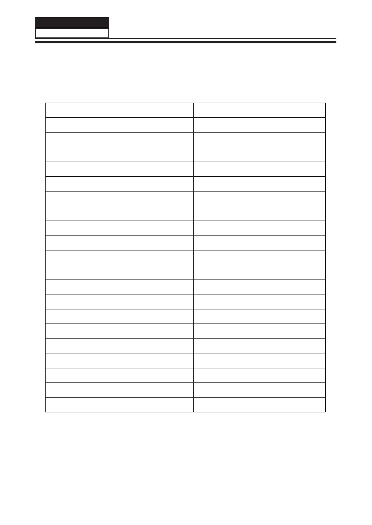
Model HBTV-22D02FD
Screen Size 22 inches
Aspect Ratio 16:9
Resolution 1920*1080
Response Time (ms) 5ms
Angel of View H:170/V:160
Color Display 16.7M
No. of Preset Channels 181
OSD Language English/Brazil Portuguese
Color System PAL/NTSC/ISDB-T
Audio System M/N
Audio Output Power (Built-in) (W) 3W*2
Audio Output Power (outer) (W) No
Total Power Input (W) 35W
Voltage Range (V) AC100V~240V
Power Frequency (Hz) 50~60Hz
Time of Sleep Timer (MINS) 240Min
Net Weight (KG) 3.17
Gross Weight (KG) 3.75
Net Dimension (MM) 528/160/388
Packaged Dimension (MM) 620/120/445
Chapter 2. Specification
2-1. Specification list
HBTV-22D02FD

Service Manual
9
2-2. External pictures
Front Side
Back Side
HBTV-22D02FD

Chapter 3. Disassemble and Assemble
3-1. Remove the Stand
1. Lay down the unit so that back cover faces
upward.
2. Remove the 1 screw from the back cover
which are indicated with the number in the
picture above.
3. Remove the stand (See picture 2).
3-2. Remove the Back Cover
1. Remove the 2 and 3 screws indicated in
picture 1.
2.Uncover the equipment, the FFC wire and
LVDS wire are shown below(See picture 3).
Remove the FFC wire and LVDS wire from
the panel.
3. Then remove the back cover from the unit.
(See picture 4).
picture 1
picture 2
picture 3
picture 4
Service Manual
10
HBTV-22D02FD

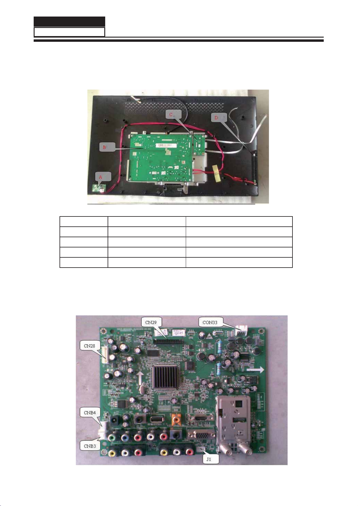
3-3. Remove the Main Board &
Small Board
There are four boards in the machine:
A:Remote Control Board;B:Main Board;C:LED
Driver Board ;D:Keypad Board (See picture 5).
3-3-1. Remove the Mainboard and the
Driver Board
3-3-2.Remove the Remote Control Board
3-3-3. Remove the Keypad Board
There's no screw in this board,pull the keypad
board out from Front Cabinet directly.
3-3-4. Remove the Speakers
Remove the two screws indicated in picture 9
Take out one speaker,then another as this.
picture 5
Remove the six screws indicated in picture 6.
Take out the mainboard and the drive board.
picture 6
Remove the screw indicated in picture 7.
Take out the mainboard and the drive board.
picture 7
picture 8
picture 9
Service Manual
11
HBTV-22D02FD
Chapter 4. Location of Controls and Components
4-1. Board Location
No. Parts number Description
4-2. Main Board (Placa Principal)
Service Manual
12
HBTV-22D02FD
A Board 410262 PCI Sensor Remoto
B Board 497375 Placa Principal (V2)
C Board 410254 PCI Inversora LCD
D Board 410260 PCI do Teclado
A PLACA PRINCIPAL SOMENTE PODE SER SOLICITADA
ATRAVÉS DO SUPORTE TÉCNICO !!!

4-2-1. Function Description:
Main Board
Process signal which incept from exterior equipment then translate into signal that panel can display.
4-2-2. Connector definition
Main board connector
CNB4 CNB3
Pin number Signal name Pin number Signal name
1+5V 1GND
2 IR 2 KEY1
3 RED 3 KEY2
4 GREEN
5 GND
J1
Pin number Signal name
1+5V
2GND
3RX
4TX
CN28 CON33
Pin number Signal name Pin number Signal name
1PW_ON 1R+
2 GND 2 R-
3 GND 3 L-
4 ADJ 4 L+
5 PB-ON
6 +12V
7 +12V
Notes:
CNB4:Remote Control connector ; to ABoard
CNB3:Keypad connector ; to D Board
J1:Upgrade connector
CN28:Driver connector ; to C Board
CON33:Speaker connector ; to Speaker
CN29:LVDS connector ; to Panel
CN29
Pin number Signal name
1 VDD
2 VDD
3 VDD
4 GND
5 GND
6 GND
7 RXO0-
8 RXO0+
9 RXO1-
10 RXO1+
11 RXO2-
12 RXO2+
13 GND
14 GND
15 RXOC-
16 RXOC+
17 RXO3-
18 RXO3+
19 RXE0-
20 RXE0+
21 RXE1-
22 RXE1+
23 RXE2-
24 RXE2+
25 GND
26 GND
27 RXEC-
28 RXEC+
29 RXE3-
30 RXE3+
31 GND
32 GND
Service Manual
13
HBTV-22D02FD
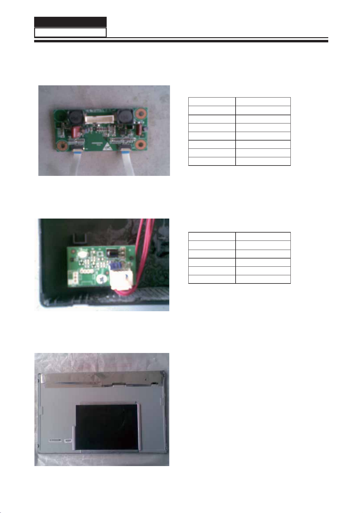
4-3. Driver Board
4-4. Remote Control Board
CN1 Signal name
1PW_ON
2 GND
3 GND
4 ADJ
5 PB-ON
6 +12V
7 +12V
4-5. LED Panel
Function description:To supply power for Panel.
CN1 Signal name
1+5V
2IR
3 RED
4 GREEN
5 GND
Function description:receive remote control
signal
Connector definition:
Connector definition:
Service Manual
14
HBTV-22D02FD
Service Manual
15
HBTV-22D02FD
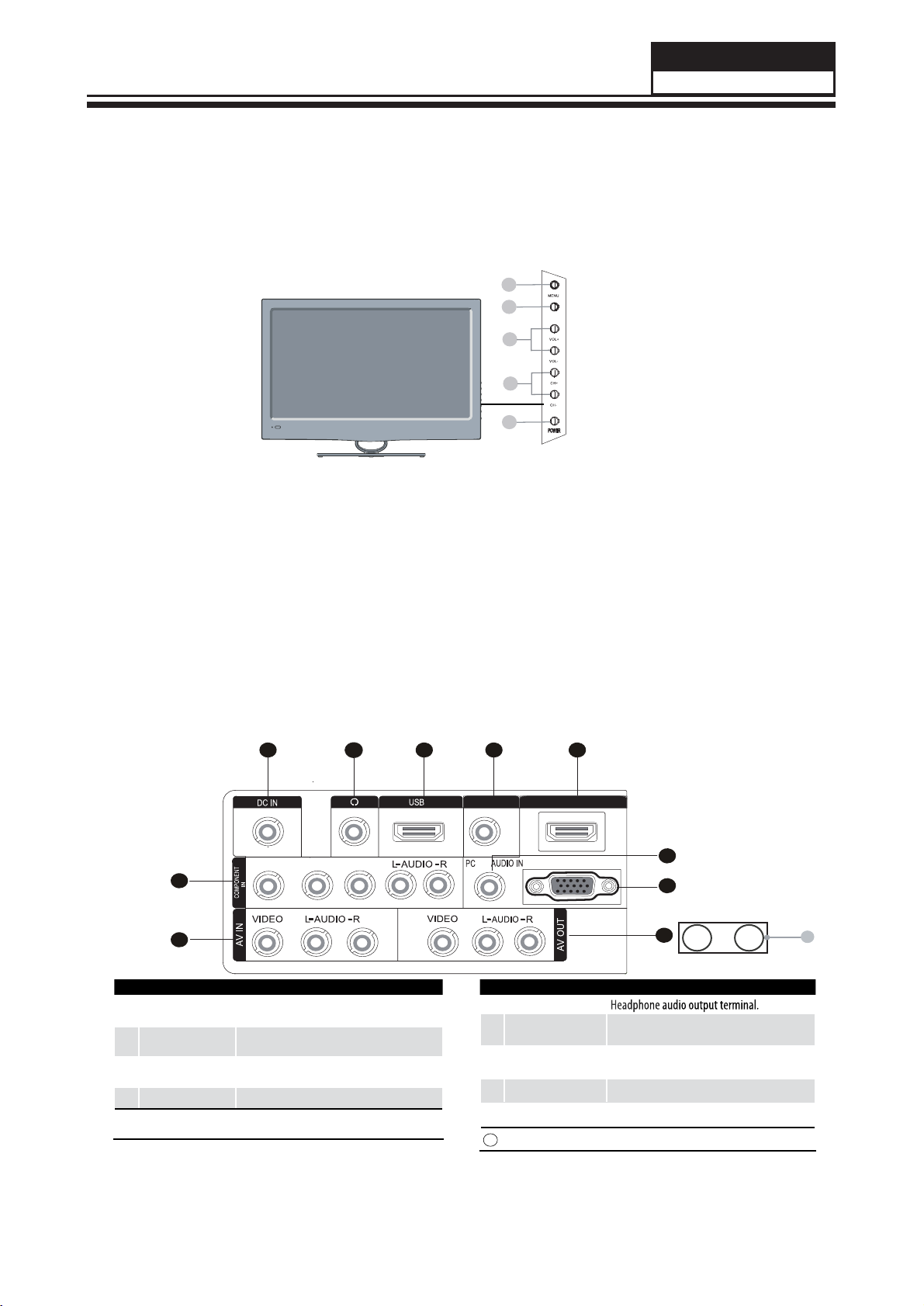
Chapter 5. Operation Instructions
5-1. Front Panel Controls
1. MENU :Menu display
2. INPUT :All input source display and OK con firm.
3. VOL(+/-) :Volume increase and decrease, menu set and entry
4. CH(+/-) :Program minus and plus, menu options
5. POWER :Is used to activate the display or return to standby mode.
5-2. BACK Panel Controls
5
1
2
7 8 9
10
3
4
6
PC IN
DIGITAL OUT
(COAXIAL)
HDMI IN
1COMPONENT In Connect a component Video/Audio device to
these jacks
2AV IN Connect Video/Audio out from an Video/Audio
device to these jacks
3PC IN
Connect the monitor output connector from a PC
to the jack
4AV OUT Video/Audio output terminal
5DC IN
Connect the monitor output connector from a DC
to the jack
6Headphone Headphone audio outputterminal.
7USB Connect a USB ash drive to view PPEG2
videos,JPEG images or listen to MP3 songs.
8DIGITAL
OUT(COAXIAL) Digital/Coaxial output terminal
9HDMI Connect a signal to HDMI
0PC/DVI AUDIO Connect a PC/DVI Audio device to these jacks
IMPUT
1
2
4
3
5
ANT IN
(AIR)
ANT IN
(CABLE)
11
1 1 ANT IN Connect a CATV or AIR Antenna cabIe

Service Manual
16
HBTV-22D02FD
ENTER
ZOOM
OK
GUIDE
EXIT
REPEAT
INPUT
MTS/SAP
INFO
MUTE
VOL CH
MENU
Q.MENU
SOUND
PICTURE
Q.VIEW
P. SIZE H.LOCK
FAVORITE
CH.LIST
CC DNR
SLEEP
USB
1
2
3
4
5
6
7
8
9
10
11
12
13 14
15
16
17
18
19
20
21
22
23
24
5-3. Remote Control

Service Manual
17
HBTV-22D02FD
T
e
clas do Controle Remoto
1. Input: Pressione para selecionar a fonte de sinal desejada.
2. CC: Pressione para habilitar ou desabilitar o closed caption.
3. MTS/SAP: Pressione para alternar entre mono, estéreo e SAP.
4. P.Size: Pressione para alterar o tamanho da imagem.
5. H.Lock: Pressione para acessar o menu de bloqueios.
6. Teclado numérico: Utilize para selecionar o canal desejado.
7. Mute: Pressione para cortar temporariamente o som.
8. Teclas de volume: Pressione para aumentar ou diminuir o volume.
9. Menu: Pressione para acessar o menu principal.
10. Sound: Pressione para selecionar o modo pré-ajustado de áudio.
1 1 . T e c l a s c o l o r i d a s : Acionam ou acessam funções específicas nos menus.
12. Teclas de navegação USB: Utilize para navegar nos menus e arquivos no modo USB.
13. USB: Pressione para ter acesso direto a fonte de entrada USB.
14. Sleep: Pressione para selecionar em quanto tempo o televisor irá se desligar.
15. DNR: Pressione para habilitar ou desabilitar o redutor digital de ruídos.
16. CH.List: Pressione para acessar a lista de canais disponíveis.
17. Favorite: Pressione para acessar a lista de canais favoritos.
18. Q.View: Pressione para retornar ao último canal selecionado.
19. Teclas CH: Pressione para trocar de canal.
20. Q.Menu: Pressione para ter acesso ao menu rápido.
21. Teclas de navegação: Utilize para navegar pelos menus e funções do televisor.
22. Picture: Pressione para selecionar o modo pré-ajustado de imagem.
23. Guide: Pressione para ter acesso ao guia eletrônico de programação.
(apenas em TV digital).
24. Exit: Pressione para sair dos menus ou funções do televisor.

Service Manual
18
HBTV-22D02FD
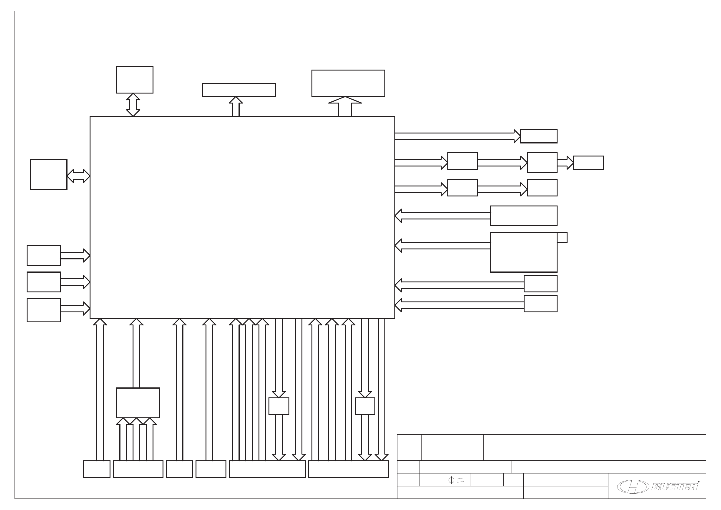
Chapter 6. Electrical Circuit
6-1. Power Tree
6-2. Wiring Connection Diagram
Revisão
S/E 1/17
A3
01
mm
Formato
Escala Dimensão Página Código matriz
Código sistema
Tol.não especificada
Revisado por: Eduardo Macedo Aprovado por: Thomas Wang Modificado por:
Elaborado por: Éber Silva
Data
10/01/11
Documento Descrição
Liberação inicial
PCI principal HBTV-22D02FD (MTK5363)
PV4
YPbPrx1
LINE IN
S-VIDEO
S-VIDEO
CVBSx2
PV1.PV2
PV3
TUNER
Tuner IF+/IF-
LINE IN
LINE IN
Audio DAC0
LINE IN
Line Out SPEAKER
Audio DAC2 HP Out
SPDIF OUT SPDIF OUT
PCMCIA
NAND
LVDS CONN
Serial SPI
PV6PV5PV7
PU1 PH3.PH4.PH5
UH19
NAND
UD3
U1
MTK5363
Video DAC OUT1
DDR2
USBx1
HDMI SWITCH
HDMIx3 VGA SART1
YPbPr1
RGB
HDMI1
HDMI2
HDMI3
USB
HDMI x1
CVBS
RGB
Video DAC OUT2
SART2
SC
CVBS/SY
U4
U1.U3
JL5
PCI1
SOCKET
Flash
PA9
U39
P34
PA3.PA4.PA7.PA8
UT1
UD2
DDR2
CVBSx2
HP Driv
UA6 HP OUT
OPA
UA4
Line Out
Audio DAC1
OPA
UA3
Line Out
Audio DAC3 OPA
UA5
AMP SP
JA1.JA2
Flash
SD/MS SD/MS
JC2
MT5363P1V1 (4 LAYERS)
Block Diagram
Table of contents
Other H-BUSTER LCD TV manuals


