7
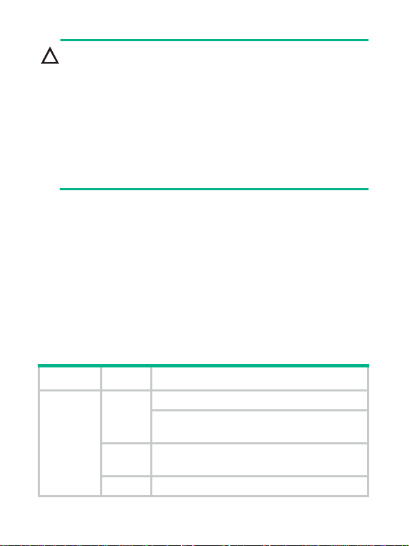
In case of a power alarm (the OUTPUT LED turns red), check
whether
output short circuit, output over-current, output
-voltage, or overheat occurred to the power module. In the
case of output short circuit, or abnormal temperature, the power
module will resume normal operation automatically when the
fault is cleared
. However,
if the power alarm is caused by output
over
-voltage, the power module will get locked up and will not
resume operation automatically. In this case, turn off the power
switch
, disconnect the power cables, and then reconnect the
power cable and turn on the power switch.
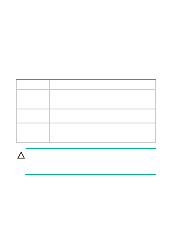
Status LEDs of the PSR1400-D
The PSR1400-D has four red/green status LEDs, which indicate the
input and output statuses of the power module and the working
status of the power module fan, respectively.
The PSR1400-D can provide PoE only when the system power
output is normal.
Table 3describes the colors and working status of the three LEDs in
different cases.
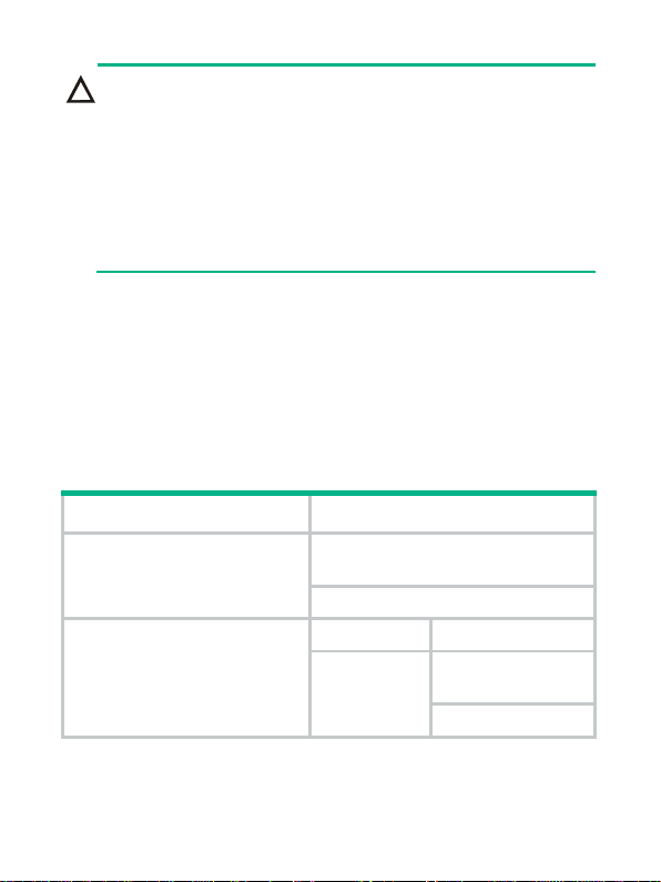
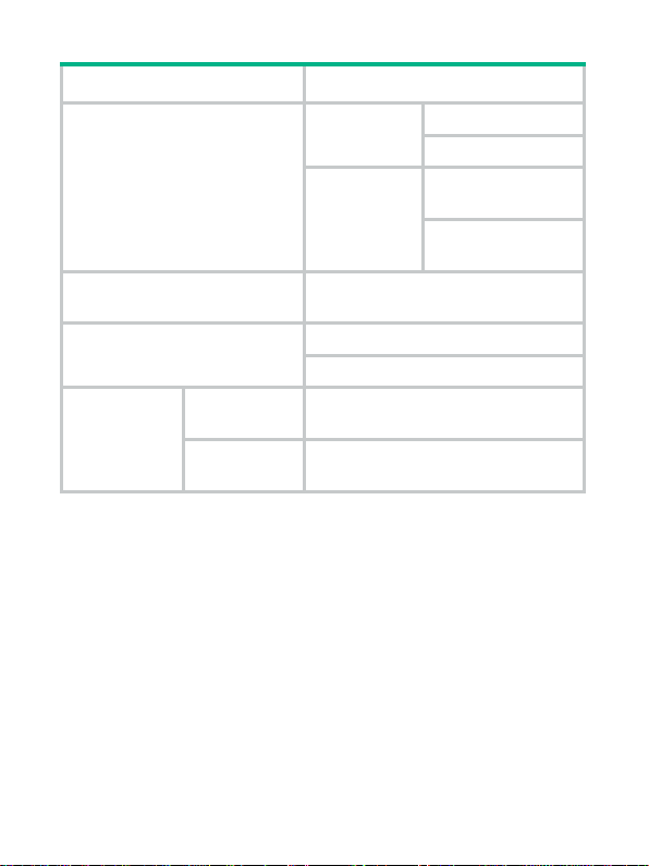
Table 4 Description of LEDs on the PSR1400-A
LED Status Meaning
INPUT
Off No power input is present.
The power input is normal but the system
switch is in the OFF position.
Green The power input is normal and the system
switch is in the ON position.
Red The power input is abnormal.