Hach POLYMETRON 8544 User manual

DOC024.98.93128
POLYMETRON Model 8544
12/2016, Edition 1
User Manual
Manuel d'utilisation

Table of contents
Specifications on page 3 Maintenance on page 16
General information on page 4 Troubleshooting on page 16
Installation on page 8 Replacement parts and accessories on page 16
Operation on page 16
Specifications
Specifications are subject to change without notice.
Table 1 General specifications
Specification Details
Operating temperature –10 to 50 °C (14 to 122 °F)
Storage temperature –5 to 40 °C (23 to 104 °F)
Relative humidity 20 to 80%, non-condensing
Altitude 2000 m (6562 ft) maximum
Overvoltage category 2
Pollution degree 2
Power requirements 24 VAC, 110–240 VAC, 50–60 Hz, 10 VA
CE compliance EN61326-1: EMC Directive
EN61010-1: LVD Directive
Warranty 1 year (EU: 2 years)
Table 2 Specifications—Air or water electrode cleaning system
Specification Details
Dimensions (W x H x D) 55 x 100 x 40 mm (9.8 x 13.8 x 5.9 in.)
Weight Approximately 0.4 kg (9.9 lbs)
Cleaning system Pressure: 0.5 to 10 bars (7.25 to 145 psi); temperature 70 °C (158 °F) maximum; flow:
400 to 4000 L/h
Environmental rating IP 65
Materials Enclosure material: Brass (MS); seal material: Fluoroelastomer (FKM), etylene
propylene diene monomer rubber (EPDM) and nitrile rubber (NBR); tubing:
Polyethylene (PE)
Table 3 Specifications—Chemical electrode cleaning system
Specification Details
Dimensions (W x H x D) 250 x 350 x 150 mm (9.8 x 13.8 x 5.9 in.)
Weight Approximately 4.5 kg (9.9 lbs)
Cleaning system Chemical reagent: air supply pressure 4 to 8 bar (58 to 116 psi); volume of reagent
supplied in each cycle: ± 10 mL
Suction height 2 m (6.5 ft) maximum
English 3

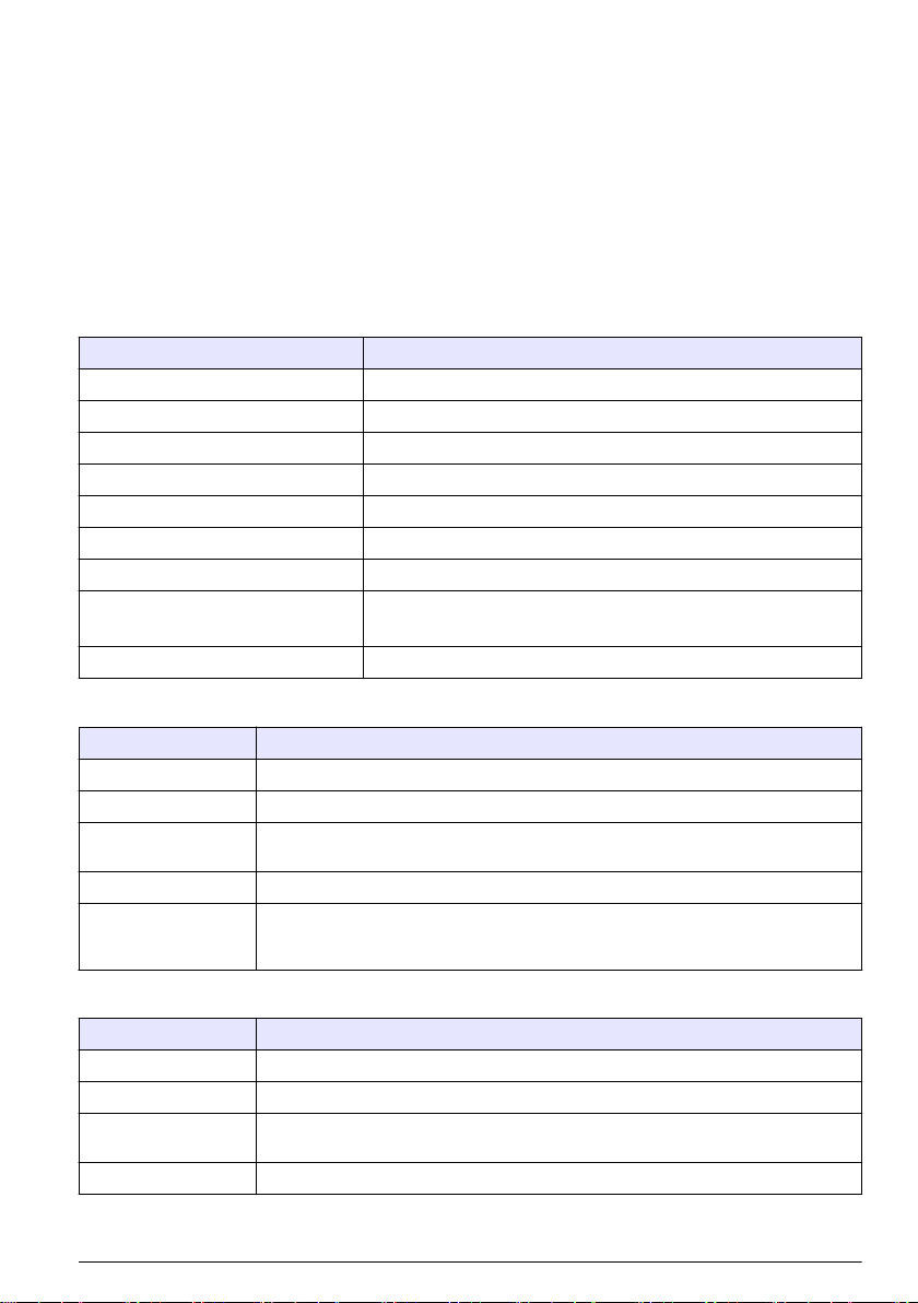
Table 3 Specifications—Chemical electrode cleaning system (continued)
Specification Details
Environmental rating IP 65
Materials Body material: Glass fiber and reinforced polyester; tubing: Polyvinyl chloride (PVC)
and PE
General information
In no event will the manufacturer be liable for direct, indirect, special, incidental or consequential
damages resulting from any defect or omission in this manual. The manufacturer reserves the right to
make changes in this manual and the products it describes at any time, without notice or obligation.
Revised editions are found on the manufacturer’s website.
Safety information
N O T I C E
The manufacturer is not responsible for any damages due to misapplication or misuse of this product including,
without limitation, direct, incidental and consequential damages, and disclaims such damages to the full extent
permitted under applicable law. The user is solely responsible to identify critical application risks and install
appropriate mechanisms to protect processes during a possible equipment malfunction.
Please read this entire manual before unpacking, setting up or operating this equipment. Pay
attention to all danger and caution statements. Failure to do so could result in serious injury to the
operator or damage to the equipment.
Make sure that the protection provided by this equipment is not impaired. Do not use or install this
equipment in any manner other than that specified in this manual.
Use of hazard information
D A N G E R
Indicates a potentially or imminently hazardous situation which, if not avoided, will result in death or serious injury.
WARNING
Indicates a potentially or imminently hazardous situation which, if not avoided, could result in death or serious
injury.
CAUTION
Indicates a potentially hazardous situation that may result in minor or moderate injury.
N O T I C E
Indicates a situation which, if not avoided, may cause damage to the instrument. Information that requires special
emphasis.
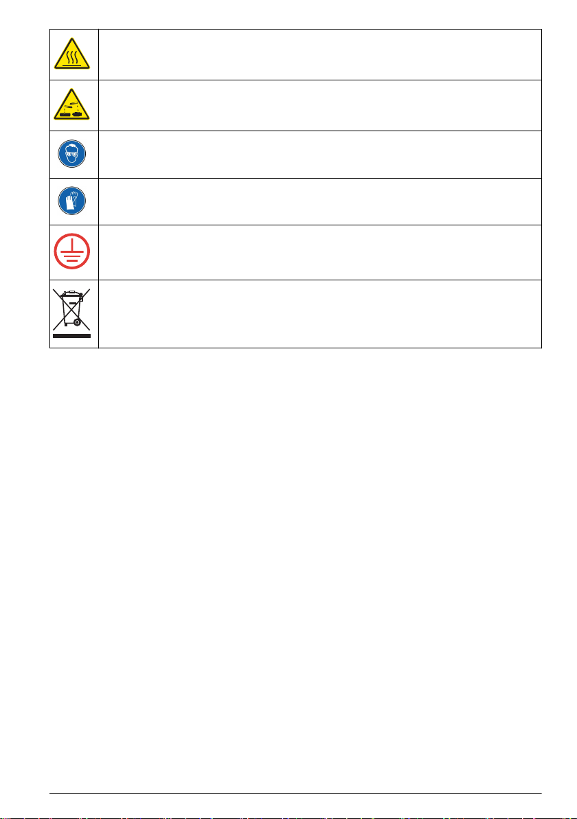
Precautionary labels
Read all labels and tags attached to the instrument. Personal injury or damage to the instrument
could occur if not observed. A symbol on the instrument is referenced in the manual with a
precautionary statement.
This is the safety alert symbol. Obey all safety messages that follow this symbol to avoid potential
injury. If on the instrument, refer to the instruction manual for operation or safety information.
This symbol indicates that a risk of electrical shock and/or electrocution exists.
4 English

This symbol indicates that the marked item can be hot and should not be touched without care.
This symbol identifies the presence of a strong corrosive or other hazardous substance and a risk of
chemical harm. Only individuals qualified and trained to work with chemicals should handle chemicals
or perform maintenance on chemical delivery systems associated with the equipment.
This symbol indicates the need for protective eye wear.
This symbol indicates the need for protective hand wear.
This symbol indicates that the marked item requires a protective earth connection. If the instrument is
not supplied with a ground plug on a cord, make the protective earth connection to the protective
conductor terminal.
Electrical equipment marked with this symbol may not be disposed of in European domestic or public
disposal systems. Return old or end-of-life equipment to the manufacturer for disposal at no charge to
the user.
Product overview
The POLYMETRON model 8544 is a cleaning system for electrodes. There are two models:
•Air or water electrode cleaning system: Models 8544.1 (220 V), 8544.2 (110 V) and
8544.3 (24 V). An electrovalve supplies air or water to the sensor tip. Refer to Figure 1.
•Chemical electrode cleaning system: Models 8544.4 (220 V), 8544.5 (110 V) and 8544.6 (24 V).
A twin chamber hose pump uses an air–instrument to supply a measured volume of a cleaning
fluid with a nozzle that is installed immediately below the sensor tip. Refer to Figure 2.
The manufacturer recommends that a junction box is used to connect the POLYMETRON
9500 series or SC200 controller to the system as shown in Figure 1 and Figure 2. Then, the cleaning
interval is configured at the controller. Refer to Replacement parts and accessories on page 16 for
ordering information.
English 5

Figure 1 Air or water electrode cleaning system
1 Junction box (optional) 4 Air or water inlet 7 Nozzle for 8340/44 probes
2 Controller (optional) 5 Cleaning module (electrovalve) 8 Nozzle for 8350 probes
3 Electrovalve connector 6 Brass adapter, air or water outlet
6 English

Figure 2 Chemical electrode cleaning system
1 Junction box (optional) 6 Valve 11 Cleaning solution outlet line
2 Controller (optional) 7 Hose pump 12 Cleaning solution intlet line
3 Electrovalve 8 Nozzle for 8350 probes 13 Power line
4 Manual starting button 9 Nozzle for 8340/44 probes 14 Air inlet
5 Cleaning module 10 Cleaning solution container 15 Purge and silencer
Product components
Make sure that all components have been received. Refer to Figure 3 and Figure 4. If any items are
missing or damaged, contact the manufacturer or a sales representative immediately.
Figure 3 Product components—Air or water system
1 Cleaning module 2 Tubing
English 7

Figure 4 Product components—Chemical system
1 Cleaning module 2 Enclosure key 3 Tubing
Installation
WARNING
Multiple hazards. Only qualified personnel must conduct the tasks described in this section of the
document.
Installation guidelines
N O T I C E
Make sure to install the instrument vertically. Make sure that the distance between the instruments and the
cleaning container is less than 2 m (6.6 ft).
Make sure that hazardous fluids or fluids that can produce hazardous vapors are handled safely.
These fluids must be handled in accordance with local regulatory agency requirements on
permissible exposure limits.
Install the instrument:
• In a location with a flat surface to prevent the unit from movement
• In a location with minimum mechanical vibrations and electronic noise
• In a location where the power switch and power cord are visible and easily accessible
• In a location where there is sufficient clearance around it to make plumbing and electrical
connections
Keep the sample tubing as short as possible to minimize lag time. Keep the instrument away from a
heat source.
8 English

Electrical installation
D A N G E R
Electrocution hazard. Always remove power to the instrument before making electrical connections.
Wiring for power
D A N G E R
Electrocution hazard. Protective Earth Ground (PE) connection is required.
D A N G E R
Electrical shock and fire hazards. Make sure to identify the local disconnect clearly for the conduit
installation.
WARNING
Potential Electrocution Hazard. If this equipment is used outdoors or in potentially wet locations, a
Ground Fault Interrupt device must be used for connecting the equipment to its mains power source.
WARNING
Electrical shock and fire hazards. Make sure that the user-supplied power cord and non‐locking plug
meet the applicable country code requirements.
N O T I C E
Install the device in a location and position that gives easy access to the disconnect device and its operation.
Supply power to the instrument with conduit or a power cable. Make sure that a circuit breaker with
sufficient current capacity is installed in the power line. The circuit breaker size is based on the wire
gauge used for installation.
For installation with conduit:
• Install a local disconnect for the instrument within 3 m (10 ft) of the instrument. Put a label on the
disconnect that identifies it as the main disconnect device for the instrument.
• Make sure that the power and safety ground service drops for the instrument are 18–12 AWG and
the wire insulation is rated for 300 VAC or higher.
• Connect equipment in accordance with local, state or national electrical codes.
• Connect the conduit through a conduit hub that holds the conduit securely and seals the enclosure
when tightened.
• If metal conduit is used, make sure that the conduit hub is tightened so that the conduit hub
connects the metal conduit to safely ground.
For installation with a power cable, make sure that the power cable is:
• Less than 3 m (10 ft) in length
• Rated sufficient for the supply voltage and current. Refer to the requirements in Specifications
on page 3.
• Rated for at least 60 °C (140 °F) and applicable to the installation environment
• Not less than 18 AWG with applicable insulation colors for local code requirements
• A power cable with a three-prong plug (with ground connection) that is applicable to the supply
connection
English 9

• Connected through a cable gland (strain relief) that holds the power cable securely and seals the
enclosure when tightened
• Does not have a locking type device on the plug
Connect conduit or a power cord
Connect the instrument to power with conduit or a power cord. Refer to Wiring for power on page 9.
Make connections at the same terminals, regardless of the type of wire used. Put each wire into the
applicable terminal until the insulation is flush against the connector with no bare wire seen. Pull
lightly after insertion to make sure that there is a tight connection.
Connect air or water system
Connect the instrument to power with conduit or a power cord. Refer to Wiring for power on page 9.
Make connections at the same terminals, regardless of the type of wire used. Put each wire into the
applicable terminal until the insulation is flush against the connector with no bare wire seen. Pull
lightly after insertion to make sure that there is a tight connection.
1. Complete the steps shown in Figure 5.
2. Connect the live (L), neutral (N), and ground (G) wires to the electrovalve connector as shown in
Figure 6 and Table 4.
Figure 5 Electrical wiring connection—Air or water system
10 English

Figure 6 Power cord or conduit connection
1 Contact insert. 3 Protective earth ground (G)
terminal
5 Seal
2 Hot or phase (L) terminal 4 Neutral (N) terminal 6 Union nut
Table 4 Wiring information—AC power
Terminal Description Color–North America Color–EU
L Hot or phase Black Brown
N Neutral White Blue
G Protective earth ground Green Yellow with green stripe
Connect the chemical system
Connect the instrument to power with conduit or a power cord. Refer to Wiring for power on page 9.
Make connections at the same terminals, regardless of the type of wire used. Put each wire into the
applicable terminal until the insulation is flush against the connector with no bare wire seen. Pull
lightly after insertion to make sure that there is a tight connection.
1. Complete the steps shown in Figure 7.
2. Connect the live (L), neutral (N), and ground (G) wires to the electrovalve connector as shown in
Figure 6 on page 11 and Table 4 on page 11.
3. Close the device door.
English 11

Figure 7 Electrical wiring connection—Chemical system
Connect the junction box (optional)
The manufacturer recommends that a junction box is used to connect the POLYMETRON
9500 series or SC200 controller to the system. Then, the cleaning interval is configured at the
controller.
1. Complete the steps shown in Figure 8.
2. Connect the power, controller cable and electrovalve cable to the junction box terminal. Refer to
Table 5.
3. Connect the controller cable to the controller relay. Refer to the controller documentation.
12 English

Figure 8 Junction box connection
1 Power supply 3 Cable to the controller
2 Terminals connector 4 Cable to the electrovalve connector
Table 5 Wiring information—Junction box
Terminal Description Color—North America Color—EU
1 Protective earth ground (G) Green Yellow with green stripe
2 Hot or phase (L) Black Brown
3 Neutral (N) White Blue
4 Hot or phase (L) Black Brown
5 Neutral (N) White Blue
6 Protective earth ground (G) Green Yellow with green stripe
Plumbing
D A N G E R
Personal injury hazard. Installation or maintenance of a pressurized system can be dangerous. Always
remove pressure from the system before any installation or maintenance task.
English 13

D A N G E R
Chemical exposure hazard. Obey laboratory safety procedures and wear all of the personal protective
equipment appropriate to the chemicals that are handled. Refer to the current safety data sheets
(MSDS/SDS) for safety protocols.
CAUTION
Chemical exposure hazard. Dispose of chemicals and wastes in accordance with local, regional and
national regulations.
Make sure to use a clean air or water line for the pressure system. If necessary, install a dirt filter
before the valve inlet (≤ 400 µm).
1. Remove dirt in the pipelines, if applicable.
2. Clean and deburr all of the connecting pipe and tubing before installing.
Plumb the system—Air or water system
N O T I C E
Do not use the body of the electrovalve as a lever arm or damage to the instrument can occur.
Connect the air or water line to the electrovalve. The arrow on the instrument shows the flow
direction. Complete the steps shown in Figure 9.
Note: If used, make sure that sealing material does not get into the instrument.
Figure 9 Air or water system plumbing
14 English

Plumb the system—Chemical system
D A N G E R
Chemical exposure hazard. Obey laboratory safety procedures and wear all of the personal protective
equipment appropriate to the chemicals that are handled. Refer to the current safety data sheets
(MSDS/SDS) for safety protocols.
Plumb a container of cleaning solution to the system. Use the cleaning solution that is specified for
the type of contamination that is in the sample. The cleaning solution must not dissolve or damage
the instrument components. Make sure that the cleaning solution does not cause harmful gases or
materials.
1. Unroll the tubing that is attached at the bottom of the instrument (cleaning solution inlet line).
2. Complete the steps shown in Figure 10.
Figure 10 Chemical system plumbing
English 15

Operation
WARNING
Burn hazard. The electrovalve surface gets hot. Do not touch.
Set the instrument to on to start the cleaning cycle.
If a junction box and a controller is used, configure the cleaning at the controller. Refer to the
controller documentation.
The user can manually start a cleaning cycle with the switch button in the junction box or the manual
start button. Refer to Figure 2 on page 7.
Maintenance
Look for leaks
WARNING
Burn hazard. The electrovalve surface gets hot. Do not touch.
CAUTION
Chemical exposure hazard. Obey laboratory safety procedures and wear all of the personal protective
equipment appropriate to the chemicals that are handled. Refer to the current safety data sheets
(MSDS/SDS) for safety protocols.
Before each use, examine all of the connectors, valves and other components for leaks. Repair leaks
as necessary.
Troubleshooting
Problem Possible cause Solution
The cleaning reagent
pressure is not
sufficient.
The tube distance is too
long.
Make sure that the distance between the instrument and
the cleaning container is less than 2 m (6.6 ft).
The system is off. Power is not supplied to
the instrument.
Make sure that power is supplied to the instrument and
the instrument switch is set to on. If there is power and the
instrument does not start, contact technical support.
Replacement parts and accessories
WARNING
Personal injury hazard. Use of non-approved parts may cause personal injury, damage to the
instrument or equipment malfunction. The replacement parts in this section are approved by the
manufacturer.
Note: Product and Article numbers may vary for some selling regions. Contact the appropriate distributor or refer to
the company website for contact information.
16 English

Replacement parts
Description Item no.
PP nozzle with 3/4 in. NPT thread
for combined sensors
08350=A=7000
PVDF nozzle with 3/4 in. NPT
thread for combined sensors
08350=A=7500
PP nozzle for electrodes installed in
8340/44 probes (fitting PG13,5)
363381,60000
PVDF nozzle for electrodes installed
in 8340/44 probes (fitting PG13,5)
363381,50000
Accessories
Description Item no.
POLYMETRON Model
8544.7 junction box
08544=A=007
ND 4/6 polyethylene tube 151575,00006
2-wires shield cable to connect
system to controller
150453,06611
English 17

Table des matières
Spécifications à la page 18 Entretien à la page 31
Généralités à la page 19 Recherche de panne à la page 31
Installation à la page 23 Pièces de rechange et accessoires à la page 31
Fonctionnement à la page 31
Spécifications
Les spécifications peuvent faire l’objet de modifications sans préavis.
Tableau 1 Caractéristiques générales
Spécification Détails
Température de fonctionnement -10 à 50 °C (14 à 122 °F)
Température de stockage -5 à 40 °C (23 à 104 °F)
Humidité relative 20 à 80 %, sans condensation
Altitude 2 000 m (6 562 pieds) maximum
Catégorie de surtension 2
Degré de pollution 2
Alimentation requise 24 VCA, 110 - 240 VCA, 50 - 60 Hz, 10 VA
Conformité CE EN61326-1 : Directive CEM
EN61010-1 : Directive basse tension
Garantie 1 an (UE : 2 ans)
Tableau 2 Caractéristiques – Système de nettoyage d'électrode à air ou eau
Spécification Détails
Dimensions (L x H x P) 55 x 100 x 40 mm (9,8 x 13,8 x 5,9 po)
Poids Environ 0,4 kg (9,9 lb)
Système de nettoyage Pression : 0,5 à 10 bars (7,25 à 145 psi) ; température : 70 °C (158 °F)
maximum : débit : 400 à 4 000 L/h
Classement environnemental IP65
Matériaux Matériau du boîtier : laiton (MS) ; matériau d'étanchéité : fluoroélastomère (FKM),
caoutchouc éthylène-propylène-diène monomère (EPDM) et caoutchouc nitrile
(NBR) ; tuyau : polyéthylène (PE)
Tableau 3 Caractéristiques – Système de nettoyage d'électrode chimique
Spécification Détails
Dimensions (L x H x P) 250 x 350 x 150 mm (9,8 x 13,8 x 5,9 po)
Poids Environ 4,5 kg (9,9 lb)
Système de nettoyage Réactif chimique : pression d'air de 4 à 8 bars (58 à 116 psi) ; volume de réactif
fourni à chaque cycle : ± 10 mL
Hauteur d'aspiration 2 m (6,5 pieds) maximum
18 Français

Tableau 3 Caractéristiques – Système de nettoyage d'électrode chimique (suite)
Spécification Détails
Classement environnemental IP65
Matériaux Matériau du boîtier : polyester renforcé de fibre de verre ; tuyau : polychlorure de
vinyle (PVC) et PE
Généralités
En aucun cas le constructeur ne saurait être responsable des dommages directs, indirects, spéciaux,
accessoires ou consécutifs résultant d'un défaut ou d'une omission dans ce manuel. Le constructeur
se réserve le droit d'apporter des modifications à ce manuel et aux produits décrits à tout moment,
sans avertissement ni obligation. Les éditions révisées se trouvent sur le site Internet du fabricant.
Consignes de sécurité
A V I S
Le fabricant décline toute responsabilité quant aux dégâts liés à une application ou un usage inappropriés de ce
produit, y compris, sans toutefois s'y limiter, des dommages directs ou indirects, ainsi que des dommages
consécutifs, et rejette toute responsabilité quant à ces dommages dans la mesure où la loi applicable le permet.
L'utilisateur est seul responsable de la vérification des risques d'application critiques et de la mise en place de
mécanismes de protection des processus en cas de défaillance de l'équipement.
Veuillez lire l'ensemble du manuel avant le déballage, la configuration ou la mise en fonctionnement
de cet appareil. Respectez toutes les déclarations de prudence et d'attention. Le non-respect de
cette procédure peut conduire à des blessures graves de l'opérateur ou à des dégâts sur le matériel.
Assurez-vous que la protection fournie avec cet appareil n'est pas défaillante. N'utilisez ni n'installez
cet appareil d'une façon différente de celle décrite dans ce manuel.
Interprétation des indications de risques
D A N G E R
Indique une situation de danger potentiel ou imminent qui entraînera la mort ou de graves blessures si elle n'est
pas évitée.
AVERTISSEMENT
Indique une situation de danger potentiel ou imminent qui peut entraîner la mort ou de graves blessures si elle
n'est pas évitée.
ATTENTION
Indique une situation de danger potentiel qui peut entraîner des blessures mineures ou modérées.
A V I S
Indique une situation qui, si elle n'est pas évitée, peut occasionner l'endommagement du matériel. Informations
qui doivent être soulignées.
Etiquettes de mise en garde
Lisez toutes les informations et toutes les étiquettes apposées sur l’appareil. Des personnes peuvent
se blesser et le matériel peut être endommagé si ces instructions ne sont pas respectées. Un
Français 19

symbole sur l'appareil est référencé dans le manuel et accompagné d'une déclaration de mise en
garde.
Ceci est le symbole d'alerte de sécurité. Se conformer à tous les messages de sécurité qui suivent ce
symbole afin d'éviter tout risque de blessure. S'ils sont apposés sur l'appareil, se référer au manuel
d'utilisation pour connaître le fonctionnement ou les informations de sécurité.
Ce symbole indique qu'il existe un risque de choc électrique et/ou d'électrocution.
Ce symbole indique que l’élément signalé peut être chaud et que des précautions doivent être prises
avant de le toucher.
Ce symbole identifie la présence d’une substance fortement corrosive ou autre substance
dangereuse et donc, un risque de blessure chimique. Seuls les individus qualifiés et formés pour
travailler avec des produits chimiques doivent manipuler des produits chimiques ou procéder à des
travaux de maintenance sur les systèmes de distribution chimique associés à l’équipement.
Ce symbole indique la nécessité de porter des lunettes de protection.
Ce symbole indique la nécessité de porter des protections pour les mains.
Ce symbole indique que l'élément marqué nécessite une connexion de protection à la terre. Si
l'appareil n'est pas fourni avec une mise à la terre sur un cordon, effectuez la mise à la terre de
protection sur la borne de conducteur de protection.
Le matériel électrique portant ce symbole ne doit pas être mis au rebut dans les réseaux domestiques
ou publics européens. Retournez le matériel usé ou en fin de vie au fabricant pour une mise au rebut
sans frais pour l'utilisateur.
Présentation du produit
Le POLYMETRON modèle 8544 est un système de nettoyage des électrodes. Il existe en deux
modèles :
•Système de nettoyage d'électrode à air ou hydraulique : modèles 8544.1 (220 V),
8544.2 (110 V) et 8544.3 (24 V). Une électrovanne conduit l'air ou l'eau jusqu'à la pointe du
capteur. Voir Figure 1.
•Système de nettoyage d'électrode chimique : modèles 8544.4 (220 V), 8544.5 (110 V) et
8544.6 (24 V). Une pompe tubulaire à double chambre utilise un instrument pneumatique pour
fournir une mesure de liquide de nettoyage, à l'aide d'une buse installée juste au-dessous de la
pointe du capteur. Voir Figure 2.
Le fabricant recommande l'utilisation d'un bornier de raccordement pour connecter le
POLYMETRON 9500 ou le transmetteur SC200 au système comme illustré en Figure 1 et Figure 2.
L'intervalle entre les cycles de nettoyages se configure ensuite au niveau du transmetteur. Référez-
vous à la section Pièces de rechange et accessoires à la page 31 pour les modalités de
commande.
20 Français
Table of contents
Languages:
Other Hach Water Pump manuals
Popular Water Pump manuals by other brands

Power Fist
Power Fist 8624736 manual

Little Giant
Little Giant WRS-5 owner's manual

water source
water source WSTPC50 operating instructions

ARJO HUNTLEIGH
ARJO HUNTLEIGH Flowtron Excel Instructions for use

red lion
red lion RL-SC33T Installation and owner's manual

Little Giant
Little Giant PE-2F-PW Series quick start guide

Smith & Nephew
Smith & Nephew DOUBLEFLO instruction manual

Ecoflo
Ecoflo EFSWJ5 owner's manual

Little Giant
Little Giant VCMX Series owner's manual

Little Giant
Little Giant 2E-38N Series manual

Great Plains Industries, Inc.
Great Plains Industries, Inc. HP-90 owner's manual

Alfalaval
Alfalaval OptiLobe 22 quick start guide