INSTALLATION INSTRUCTIONS FOR MODEL H00961EA
IMPORTANT: REVIEWALL INSTRUCTIONS, PARTS LISTS, & INSTALLATION DIAGRAMS BEFORE
STARTING INSTALLATION
HORNASSEMBLY
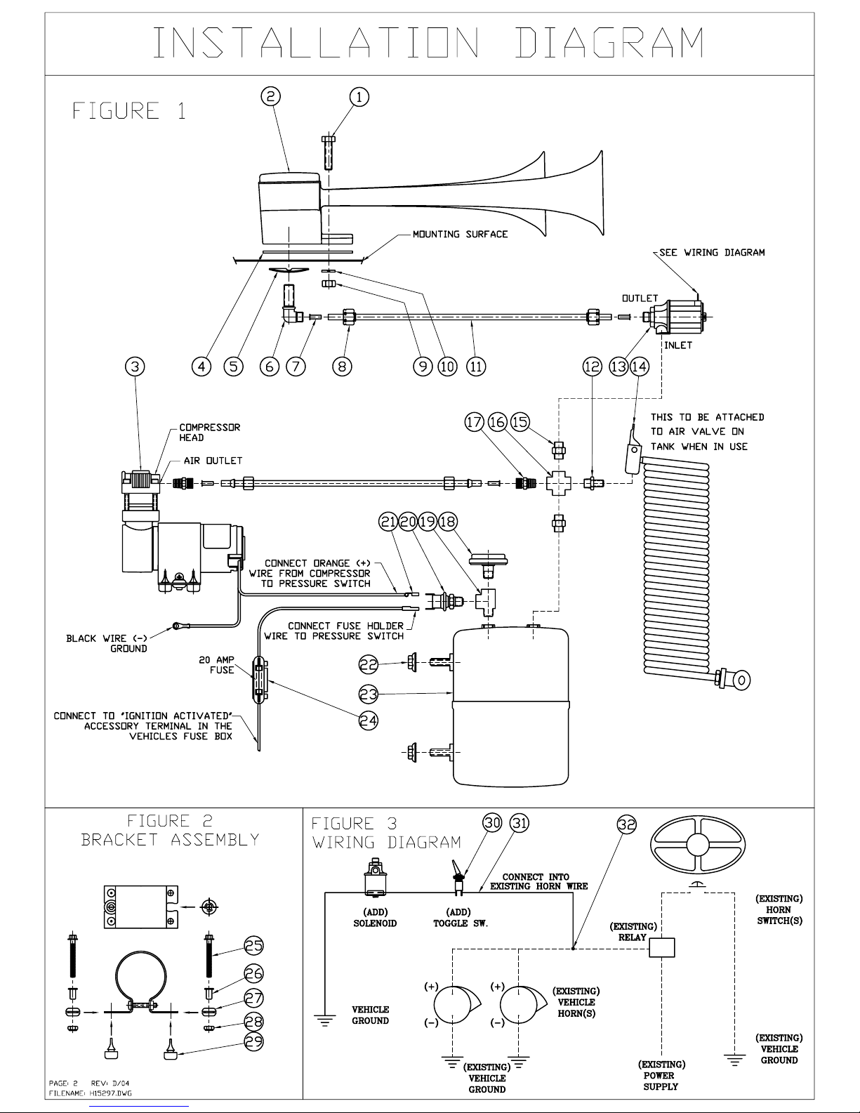
1. For best results, mount horns in an unobstructed opening for sound to carry straight ahead. If possible mount
with a slight downward angle to allow moisture to drain out.
2. For roof mount installation: If vehicle is equipped with interior roof trim panel, remove to install horn.
3. Drill 1/2 in. and 11/32 in. holes (use mounting pad for template, item#4) in position desired for horn.
4. Place mounting pad between base of horn and top of vehicle roof.
5. Place tension washer (item#5) on mounting elbow (item#6) as shown in figure 1, next thread the elbow into
the base of the horn from under the roof. Insert screw (item#1) through hole of horn base and roof, attach
lockwasher (item#10) and hex nut (item#9). Connect nylon tubing (item#11) to mounting elbow and run tube
down to tank location. Replace trim panel.
TANKASSEMBLY
1. Select mounting location for air tank (item#23) keeping in mind the orientation of the tank and visibility of the
air gage. (See Figure 1 for sample installation)
2. Thread brass fitting (item#15) into brass cross (item#16), then install brass cross fitting into either tank outlet.
Next thread other brass fitting (item#15) into brass cross and into solenoid threaded inlet (item#13). In remain-
ing (2) outlets of the brass cross, thread, tire valve (item#12), and brass fitting (item#17).
3. Thread brass tee fitting (item#19) into remaining tank outlet. Thread the pressure gage (item#18) and pres-
sure switch (item#20) into the tee.
CAUTION: Tighten pressure switch and pressure gage on brass hex body only.
4. To mount tank drill (2) 11/32 in. diameter holes spaced 4 in. apart in a rigid surface. Insert tank studs through
the holes and secure with locknuts (item#22).
COMPRESSORASSEMBLY
1. As shown in figure 2, slide the (2) grommets (item#27) into slots. Next push the (2) brass eyelets (item#26)
into the grommets. Pull the (4) bumpers (item#29) through the (4) round holes on the bracket.
2. Clamp compressor head and install brass fitting (item#17) into air outlet as shown in figure 1.
3. Mount compressor on rigid support. Do not mount on fender well, firewall or other flexible material. Locate
compressor in area with good air flow and away from road surface to avoid excessive water and dirt conditions.
4. Mounting requires (2) holes spaced 2 3/16 in. apart, each having a diameter of 7/32 in.
5. To mount compressor, insert 10-32 bolt (item#25) through the brass eyelet and through the 7/32 in. hole.
Secure with the 10-32 nut (item#28) as shown in figure 2. Do not overtighten mounting bolts.
6. Connect nylon tubing from air outlet fitting to the brass male connector on the tank as shown in figure 1.
ELECTRICALASSEMBLY
1.As shown in figure 1 connect orange (+) wire from compressor motor to either pressure switch terminal.
Next, connect fuse holder (item#24) to the other pressure switch terminal. Install other end of fuse holder to
“ignition activated” accessory terminal in fuse panel.Attach motor’s black wire (-) to metal ground.
2.As shown in figure 3 mount toggle switch (item#30) on or under the dash in a location easily accessible to the
driver. Connect wire (item#31) from vehicle ground to either solenoid terminal (item#13). Connect other sole-
noid terminal to either terminal on the toggle switch. Connect remaining toggle switch terminal in line with the
existing horn wire using a wire splice connector (item#32). With toggle switch in “off” position, only the ve-
hicles electric horn will operate. With switch in “on” position, air horns and electric horn will be operated.
NOTE: Compressor starts automatically when pressure drops below 110 psi. If more than 4 minutes are re-
quired to pump tank to full pressure (110-135 psi) with engine running and compressor does not shut off, check
all connections with soapy water or bubble solution for leaks. Use thread sealant on all uncoated pipe threads.
Maximum cycle time 7 minutes with 30 minute cool down.
CAUTION: Check local noise abatement ordinances to avoid legal violations. Page 1 Rev: D/04
Filename:H15297.p65