Haff & Schneider 3D-Touch Probe 2007 User manual

Bedienungsanleitung
3D Taster Analog / 3D Probe Analogue
Prüfprotokoll, Bedienungsanleitung und Qualitätszertifikat /Testreport,
Operation Instructions and Qualitycertificate
Printed in Germany

3
PRÜFPROTOKOLL – INS PECTION RE-
Gegenstand: 3D-Taster 2007 mit Messwegkalibrierung
Object: 3D-Touch Probe 2007 with measurement calibration
Serien-Nr./Serial No.
Prüfdatum/Inspection Date
Prüfer/Inspector
Die Prüfung erfolgt in Anlehnung nach VDI/auf einer Digital-Messuhr/
1/1000-Anzeige/Genauigkeit 0,002/kalibriert.
The inspection is made following VDI/on a digital dial gauge/
1/1000-display/accuracy 0.002 calibrated.
Prüfergebnisse
Test Results
Achse zulässig Ist-Wert
axis admissible actual value
X(+/–) 0,01
Y(+/–) 0,01
Z(+/–) 0,01
Auswertung/Evaluation i.O.
Sichtprüfung/Visual Inspection i.O.
Funktionstest/Functional Test i.O.
X´
Z´
Y´
PRÜFPROTOKOLL - INSPECTION REPORT
für analogen 3D-Taster 2007
for analog 3D-Touch Probe 2007

D
5
Bedienungsanleitung analoger 3D-Taster 2007
1. 3D-Taster-Aufnahme und Rundlaufkontrolle
1.1 3D-Taster in Flächenspannfutter spannen und in Maschinenspindel einsetzen.
Tasteinsatz auf festen Sitz prüfen und Rundlauf am Tasteinsatz (Tastkugel) kon-
trollieren (s.Punkt 3.2 Tasteinsatzwechsel). Bei Bedarf Rundlauf nachjustieren
(s.Punkt 4 Rundlauf justieren).
1.2 Bringen Sie bei der Messwegkalibrierung über die Justierschrauben die Zifferblatt-
nullstellung mit dem Zeiger in Deckung.
Die Messgenauigkeit des 3D-Tasters 2007 können Sie mit einem Endmaß über-
prüfen.
1.3 Eektive Tasterlänge (TL) ermitteln (s.Abb.2):
– Effektive Tasterlänge TL als Werkzeuglänge in den Werkzeugspeicher
der Maschinensteuerung eingeben (z.B.unter T99).
– Werkzeugaufruf: 3D-Taster (z.B. T99).
2. Antasten des Werkstücks
– Maschinenspindel im Stillstand, Kühlmittelzufuhr ausgeschaltet.
–Antastäche/Werkstückkante im rechten Winkel anfahren (s.Abb.3).
Beim Antasten darf die Tastkugel nicht an der Werkstückkante entlang gefahren
werden (führt zu falschen Ergebnissen). Das Gerät vor demAntasten an das Werk-
stück in das Blickfeld des Bedieners drehen. Falls irrtümlich nach dem Anfahren
des Tasters am Gerät gedreht wird, muss der Antastvorgang wiederholt werden.
2.1 Radiales und axiales Antasten:
– Skalierung der 3D-Taster-Anzeige beobachten.
– Nach Berührung derAntastäche bewegt sich der Zeiger in Richtung Nullanzeige.
– Beim Standard-Tasteinsatz kann an der Skalierung direkt das exakte Differenzmaß
abgelesen werden.
–Antasten ist beendet, wenn Nullstellung erreicht ist.
Hinweis:
Wird die Nullstellung überfahren, muss der Antastvorgang wiederholt werden.
– Maschinenspindelachse = Antastachse
Abbildung 1
Messwegkalibrierung
Rundlaufjustierung
Tasteinsatz mit
Sollbruchstelle
Tastkugel
Werkzeugaufnahme
Aufnahmebuchse
Lineare Skala
TL = eektive 3D-Tasterlänge in angetastetem Zustand (Zeiger auf Nullstellung):
In der Nullstellung verkürzt sich die Tasterlänge um den VorlaufwegV = 2,00 mm.
Der Vorlauf (V) ist bei allen Tasteinsätzen identisch.
Eektive Tasterlänge (TL) = Gesamtlänge (L) – Vorlauf (V = 2,00 mm)
D

6
D
Abbildung 2
Eektive Tasterlänge (TL) = Gesamtlänge (L) – Vorlauf (V = 2,00 mm)
Abbildung 3
3. Tasteinsätze
– Der 3D-Taster 2007 ist ab Werk mit dem Standard-Tasteinsatz
(Bestellnummer 107323) ausgerüstet.
3.1 Taster Sollbruchstelle
– Zum Schutz des Werkstücks und der Tastermechanik besitzen die Tasteinsätze eine
Sollbruchstelle (Keramikschaft).
3.2 Tasteinsatzwechsel
– Tasteinsatz mit Innensechskant-
schlüssel über Bohrung lösen
(s.Abb.).
– Neuen Tasteinsatz in Aufnahme
einschrauben und mit Innen-
sechskantschlüssel über Bohrung
(s.Abb.) festziehen.
– Rundlauf kontrollieren
3.3 Bei Tasteinsatzwechsel
(s.Punkt 3.2) muss die Werk-
zeuglänge TL neu ermittelt
und in die Maschinensteuerung
eingegeben werden!
Tastkugel
Aufnahmebuchse
Sollbruchstelle
Keramik-
isolierung
Antasten senkrecht
zur jeweiligen
Antastäche
90°
90°
LTL
= 2,00 mm
V
7
D
4. Rundlauf justieren
Rundlauf immer prüfen:
– Nach Wechsel des 3D-Tasters in der Werkzeugaufnahme (Futter)
– Nach Tasteinsatzwechsel
– Nach Tasteinsatzbruch
– Nach Kollision
4.1 Einstellung der X-Achse
4.1.1 Spindel drehen, bis Tasterachse zu Maschinenachse X parallel steht.
4.1.2 Anfahren, bis die Messuhr reagiert (s.Abb.1).
4.1.3 Messuhr auf „0“ stellen.
4.1.4 3D-Taster um 180° drehen. Die Messuhr zeigt dieAbweichung in der X-Achse
(im hier gezeigten Fall 0,12mm) (s.Abb.2).
4.1.5 Mit dem mitgelieferten Innensechskantschlüssel die Verstellschraube um die halbe
Abweichung verdrehen (in diesem Fall 0,06mm). X-Achse ist eingestellt.
Abbildung 1 Abbildung 2
4.2. Einstellung derY-Achse
4.2.1 3D-Taster um 90° drehen (die Uhr des 3D-Tasters steht jetzt in Richtung
zur Messuhr) (s.Abb.3).
4.2.2 Messuhr auf „0“ stellen.
4.2.3 3D-Taster um 180° drehen. Die Messuhr zeigt dieAbweichung in der Y-Achse
(im hier gezeigten Fall 0,08mm) (s.Abb.4).
4.2.4 Mit dem mitgelieferten Innensechskantschlüssel die Verstellschraube um die halbe
Abweichung verdrehen (in diesem Fall 0,04mm). Y-Achse ist eingestellt.
4.2.5 Anschließend die X-Achse sicherheitshalber nochmals prüfen und eventuell erneut
korrigieren.
Abbildung 3 Abbildung 4

8
D5. Messweg kalibrieren
5.1 3D-Taster in Maschinenspindel einspannen.
5.2 Endmaß 1. Seite anfahren ,bis Zeiger in „0-Stellung“.
5.3 Maschinensteuerung X-Achse „Nullen“.
5.4 Endmaß 2. Seite anfahren:
VERFAHRWEG = ENDMASSLÄNGE (20mm) in Maschinensteuerung eingeben.
5.5 Differenz: Zeigerstellung zur „0-Stellung“ ermitteln.
5.6 Skala mit Justierschraube um „halbe Differenz“ nachstellen.
5.7 Kalibrierung kontrollieren, Schritt 5.2 bis 5.6 wiederholen.
20 mm
Justierschraube
für Kalibrierung
20 mm
Dierenz
20 mm
0-Stellung
9
D
6. Messen
6.1 Hinweis zur Vermeidung von Messfehlern
Folgende Hinweise sind zu beachten, um Messfehler zu vermeiden:
– Einspannung des 3D-Tasters in Flächenspannfutter überprüfen.
– Einspannung des Tasteinsatzes auf festen Sitz prüfen.
– Rundlauf am Tasteinsatz überprüfen.
– Nach Wechsel des Tasteinsatzes Gesamtlänge neu ermitteln und in Maschinen-
steuerung eingeben.
– Das Gerät vorAntasten an das Werkstück in das Blickfeld des Bedieners drehen.
Falls irrtümlich nach Anfahren des Tasters das Gerät gedreht wird, muss der
Antastvorgang wiederholt werden.
Nur Tasteinsatz Nr. 107323 verwenden
6.2 Antasten des Werkstücks (X-, Y- und Z-Position bestimmen)
– Maschinenspindel im Stillstand, Kühlmittelzufuhr ausgeschaltet.
6.2.1 Antastäche im rechten Winkel anfahren (s.Abb.).
6.2.2 Nach Berührung langsam weiterfahren, bis Zeiger in „0-Stellung“.
6.2.3 Maschinenachse stimmt mit Werkstückkante überein.
6.3 Bohrungsmitte bestimmen
6.3.1 X-Koordinate bestimmen:
– Taster in Bohrung einbringen und in X-Achse verfahren, bis Werkstück berührt
wird und Zeiger in „0-Stellung“ steht.
–Anzeigenwert der Steuerung (X-Achse) auf „0,000“ setzen.
Y
X

10
D
– Taster in X-Achse in entgegengesetzte Richtung verfahren, bis Werkstück berührt
wird und der Zeiger in „0-Stellung“ steht.
–Anzeige der Steuerung (X-Achse) ablesen, z.B. 15,024 mm, und mit der X-Achse
auf halben Wert, 7,512mm, verfahren undAnzeige der Steuerung (X-Achse) auf
„0,000“ setzen.
6.3.2 Y-Koordinate bestimmen:
– Vorgehensweise für dieY-Achse entsprechend Punkt 5.3.1 durchführen.
– Position der Bohrungsmitte zur Maschine ist exakt ermittelt.
6.4 Bestimmung und Korrektur der Werkstückausrichtung
6.4.1 Taster in Y-Achse verfahren, bis Werkstück berührt wird und Zeiger in „0-Stellung“
steht.
6.4.2 Anzeigenwerte der Steuerung für X- undY-Achse auf „0,000“ setzen.
6.4.3 Taster in X-Achse verfahren, z. B. um 200 mm (dx).
6.4.4 Taster in Y-Achse verfahren, bis Werkstück berührt wird und 3D-Taster in
„0-Stellung“ steht.
6.4.5 Anzeige der Steuerung (Y-Achse) ablesen, z.B. 10,48 mm (dy).
6.4.6 Korrekturwinkel ermitteln (Winkel = arctan dy/dx = 3°) undAusrichtung korrigie-
ren. Werkstückausrichtung ist korrigiert.
Y
X
Y
X
X 0,000
Y 0,000
Z 120,345
X 200,000
Y0,000
Z 120,345
X 200,000
Y 10,480
Z 120,345
11
D
6.5 Messen von Längen
6.5.1 Taster in X-Achse verfahren, bis Werkstück berührt wird und 3D-Taster in
„0-Stellung“ steht.
6.5.2 Anzeigenwert der Steuerung für X-Achse auf „0,000“ setzen.
6.5.3 Antasten der zu messenden Werkstückkante und verfahren in X-Achse, bis 3D-Taster
in „0-Stellung“ steht.
6.5.4 Ablesen der ermittelten Länge auf der Anzeige (X-Achse) der Werkzeugmaschine.
6.6 Fehlerbehebung
Wenn sich der Taster nicht in der Ausgangsposition bendet, bitte den Faltenbalg
zum Luftaustausch kurz abheben (Vakuumeffekt).
Bitte beachten Sie, dass bei einer Demontage des 3D-Tasters 2007 der Garantie-
anspruch erlischt!
25,000
X 0,000
Y 25,576
Z 30,786
X 25,000
Y 25,576
Z30,786

GB
12
Operating instructions analog 3D-Touch Probe 2007
1. 3D-Touch Probe mounting and radial run-out checking
1.1 Clamp 3D-Touch Probe in suitable chuck and position into machine spindle.
Check that stylus is rmly seated, and then check radial run-out at stylus (stylus ball)
(cf point 3.2 Change of stylus). Adjust if necessary (cf point 4 Adjustment of radial
run-out).
1.2 Align the dial “zero” position with the pointer via the setting screws when calibra-
ting the measuring path. The measuring accuracy of the 3D-Touch Probe 2007 can be
inspected with the end measure.
1.3 Determine eective total length of 3D-Touch Probe (TL) (cf g.2):
– Preset effective length of 3D-Touch Probe TL as a tool length in the tool memory
of the machine tool control (eg under T99)
– Call up tool: 3D-Touch Probe (eg T99)
2. Calipering of workpiece
– Machine spindle must be stopped and coolant supply must be switched off.
–Approach surface/workpiece edge at a right angle (cf g.3).
When approaching the workpiece, the stylus ball must not be passed along
the workpiece edge (wrong results). Place the device within the visual range
of the operator prior to starting the calipering process. The 3D-Touch Probe
must not be turned during the process. Should the device be accidentally turned,
the entire process must be repeated.
2.1 Radial and axial approach:
– Watch scale of the 3D-Touch Probe dial.
–After stylus ball has contacted the workpiece surface, indicator needle moves
towards “zero”.
– While using the standard stylus, the exact difference value can be directly read on
the scale.
– Calipering process is nished when “zero” position has been reached.
Note: If the zero position is overrun the whole procedure must be repeated.
– Machine tool spindle axis = workpiece surface
Figure 1
Measurement
calibration
Adjustment of radial run-out
Stylus with
predetermined
breaking point
Stylus ball
Tool chuck
Bushing
Linear scale
TL = eective total length of 3D-Touch Probe after nishing calipering process
(indicator needle in “zero” position):
In “zero” position the length of 3D-Touch Probe is shorter by the advance V = 2.00 mm.
The value (V) for the advance compensation ist identical for all styluses.
Eective length of 3D-Touch Probe (TL) = total length (L) – advance (V = 2.00 mm)
GB
13
Figure 2
Eektive length of 3D-Touch Probe (TL) = total length (L) – advance (V = 2.00 mm)
Figure 3
3. Styluses
– The 3D-Touch Probe 2007 is equipped with one standard stylus
(order no. 107323) on delivery.
3.1 Predetermined breaking point of stylus
– In order to protect both workpiece and the 3D-Touch Probe mechanism all styluses
have got a predetermined breaking point (ceramic shaft).
3.2 Changing the stylus
– To loosen a stylus insert an
allen key into bore hole (cf g.).
– Screw a new stylus into
the mounting hole, place an allen
key into bore hole
and tighten (cf g.).
– Check the roundness.
3.3 When changing a stylus
(cf point 3.2) the tool length TL
must be newly determined
and entered once again in the
machine control unit!
Stylus ball
Bushing
Predetermined
breaking point
Ceramic
insulation
Approach
at a right angle
to the surface
90°
90°
LTL
= 2.00 mm
V

14
GB
4. Adjustment of radial run-out
Always check radial run-out:
– After replacing the 3D-Touch Probe in the chuck of the machine tool
– After replacing a stylus
– After breakage of stylus
– After collision
4.1 Adjustment of X-axis
4.1.1 Turn spindle until X-axis of 3D-Touch Probe and X-axis of machine tool coincide.
4.1.2 Move towards stylus ball with the dial gauge until dial gauge reacts.
4.1.3 Set dial gauge to “0” (cf g.1).
4.1.4 Turn spindle with 3D-Touch Probe by 180°. The dial gauge now shows the
deviation of the X-axis (in example case dial reads 0.12mm) (cf g.2).
4.1.5 Use inbus wrench and rotate the adjusting screw by half the value of the deviation
(in example case dial would now read 0.06mm). X-axis ist now adjusted.
Figure 1 Figure 2
4.2. Adjustment of Y-axis
4.2.1 Turn spindle with 3D-Touch Probe by another 90° (the dial of 3D-Taster faces now
in the direction of the dial gauge) (cf g.3).
4.2.2 Set dial gauge to “0”.
4.2.3 Turn spindle with 3D-Touch Probe by another 180°. The dial gauge now shows the
deviation of the Y-axis (in example case 0.08 mm) (cf g.4).
4.2.4 Use inbus wrench and rotate the adjusting screw by half the value of the deviation
(in example case 0.04mm). Y-axis is now adjusted.
4.2.5 Check again true running of X-axis. In case of a remaining error carry out
adjustment again as described.
Figure 3 Figure 4
15
GB
5. Calibration of measurements
5.1 Clamp 3D-taster into machine spindle.
5.2 Approach measuring block at the rst side until needle is in “Zero” position.
5.3 Set machine control in X-axis to “zero”.
5.4 Approach measuring block at the second side:
Enter TRAVEL = MEASURING BLOCK LENGTH (20 mm) into machine control.
5.5 Difference: Determine difference of needle position to “Zero” position.
5.6 Adjust by “half the difference” using the adjustment screw.
5.7 Check calibration: Repeat steps 5.2 to 5.6.
20 mm
“Zero” position
Adjustment
screw
20 mm
Dierence
20 mm

16
GB
6. Measuring
6.1 Notes on how to avoid measuring errors
The following points must be taken into consideration in order to prevent
measuring errors:
– Check the tightness of the 3D-Touch Probe in the surface chuck.
– Check that the contact point is tightly restrained on a rm surface.
– Test the contact point.
–After changing the contact poit the total length must be newly determined
and entered into the machine control unit.
– When making contact with a workpiece the contact ball must not travel along the
workpiece edge.
– Before making contact with a workpiece the probe must be turned to the operator´s
eld of vision. If by mistake the probe is turned then the whole procedure must be
repeated.
Only use stylus from type 107323
6.2 Contacting a workpiece (determining the positions of X, Y, Z)
– Stop the machine spindle, turn off the supply of coolant.
6.2.1 Travel at a right angle to the contact surface (cf g.).
6.2.2 Once contact has been made, proceed slowly, until the indicator needle has been
reached the “zero” position.
6.2.3 The machine axis corresponds with the edge of the workpiece.
6.3 Determine the center of a bore
6.3.1 Determine coordinate X:
– Place the probe in the bore and proceed along the X-axis until it makes contact
with the workpiece and the display shows “0.000”.
– Set the display of the control unit (X-axis) to “0.000”.
Y
X
17
GB
– The probe must then proceed along the X-axis in the opposite direction until it
makes contact with the workpiece and the display shows “0.000”.
– Read off the displayed value of the machine´s control unit (X-axis),
eg 15.024mm, and proceed along X-axis at half the displayed value, 7.512mm,
and set the display of the control unit (X-axis) to “0.000”.
6.3.2 Determine Y-coordinate:
– Proceed with Y-axis in the same manner as described in point 5.3.1.
– The position of the center of the bore to the machine is exactly determined.
6.4 Determine and correct the alignment of a workpiece
6.4.1 The probe must proceed along the Y-axis until it makes contact with the workpiece
and the indicator needle moves towards “zero”.
6.4.2 Set the displayed value of the control unit (machine) for both X- andY-axis
to “0.000”.
6.4.3 The probe must proceed along the X-axis, eg for 200mm (dx).
6.4.4 The probe must proceed along the Y-axis until it touches the workpiece and the
indicator needle moves towards “zero”.
Y
X
Y
X
X 0.000
Y 0.000
Z 120.345
X 200.000
Y0.000
Z 120.345
X 200.000
Y 10.480
Z 120.345

18
GB
6.4.5 Read off the displayed value of the control unit (Y-axis), eg for 10.48 mm (dy).
6.4.6 Determine the correction angle (angle = arctan dy/dx = 3°) and realign the
workpiece accordingly. The alignment of the workpiece is now correct.
6.5 Length measurement
6.5.1 The probe must proceed along the X-axis until it makes contact with the workpiece
and the indicator needle moves towards “zero”.
6.5.2 Set the display of the machine´s control unit (x-axis) to “0.000”.
6.5.3 Make contact with the edge of the workpiece and proceed along with the X-axis until
the needle of the scale of the probe shows “zero”.
6.5.4 Read off the determined length shown in the display (X-axis) of the machine tool.
6.6 Error removal
If the probe is not in the start position, briey lift the bellows for an air exchange
(vacuum effect).
If the 3D-Touch Probe 2007 is disassembled, any warranty claim will be excluded!
25.000
X 0.000
Y 25.576
Z 30.786
X 25.000
Y 25.576
Z30.786
19
F
Notice d´utilisation du palpeur 3D 2007
1. Contrôle de laconcentricité de l´attachement/broche
1.1 Serrez le palpeur 3D dans le mandrinde serrage et insérez dans la broche de la
machine. Vérifiez l´assise ferme de l´élément de palpage et la concentricité au niveau
de l´élément de palpage (bille de palpage). Réglez de nouveau la concentricité si
besoin(voir le point Réglage de la concentricité).
1.2 Amener lors du calibrage de déplacement de mesure via la vis à tenoncarré la
positionzérodu cadranindicateur avec l´indicateur dans le couvercle. Vous pouvez
vérifier la précisionde mesure du palpeur 3D 2007 avec une cale étalon.
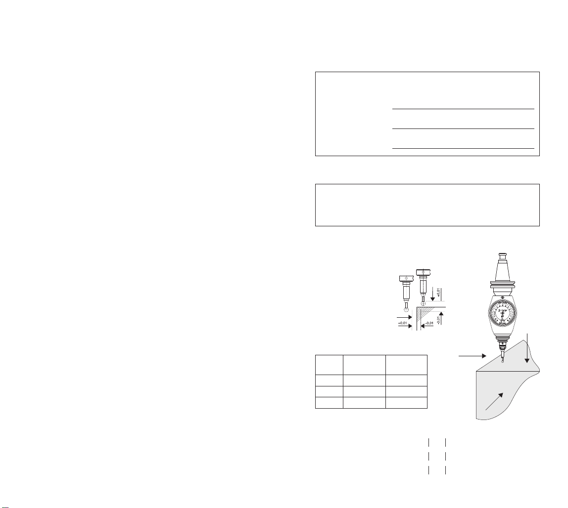
1.3 Déterminer lalongueur effective du palpeur 3D (TL) (voir figure ):
– Introduire la longueur effective entant que longueur d´outil dans la commande de
la machine (par exemple sous T99).
– Appel de l´outil: Palpeur 3D (par exemple sous T99).
. Accostage de lapièce
– La broche machine doit être à l´arrêt et la lubrificationcoupée.
– La surface à palper doit être perpendiculaire au sens d´accostage (voir figure 3).
Lors de la mesure de la pièce, le palpeur ne doit pas être déplacé le long des
surfaces à mesurer (il enrésulterait de fausses mesures).
2.1 Palpage radial et axial:
– Observer l´échelle de l´affichage du palpeur 3D.
– Après le contact avec la surface de palpage, l´indicateur se déplace dans la
directiond´affichage zéro.
– Avec le palpage standard, onpeut lire la mesure différentielle exacte directement
sur l´échelle.
– Le palpage est terminé lorsque la positionzéroest atteinte.
Note: Si la positionzéroest dépassée, la procédure doit être répétée.
– Axe de la broche de la machine = arête de palpage
Figure 1
Vis de réglage
pour le
calibrage
Vis de réglage
(I sur le côte, I sur l´arrière)
Doigt de palpage
avec amorce
de rupture Bille de palpage
Attachement
Douille de prise en charge
Echelle linéaire
TL = Longueur effective du palpeur 3D quand l´aiguille est en position «zéro»:
Enposition«zéro», la longueur effective est réduite au niveau de la course d´approche.
La course d´approche est identique quelle que soit la longueur de la touche de palpage.
Longueur effective du palpeur 3D (TL) = longueur totale (L) – course d´approche
de l´aiguille (V = ,00 mm)

20
F
Figure
Longueur effective du palpeur (TL) = longueur totale (L) – course d´approche
(V = ,00 mm)
Figure 3
3. Touches de palpage
– Le palpeur 3D 2007 est équipé ensortie d´usine d´une touche de palpage
standard no. 107323.
3.1 Amorce de rupture
– Afinde protéger la pièce ainsi
que le mécanisme du palpeur,
les touches de palpage sont munies
d´une amorce de rupture enmatière
céramique.
3.2 Changement de l´élément de palpage
– Desserrer l´élément de palpage
avec la clé mâle coudée pour vis à six
pans creux via l´alésage (voir la figure).
– Visser le nouvel élément de palpage
au niveau du logement et serrer avec
la clé mâle coudée pour vis à six pans
creux via l´alésage (voir la figure).
– Contrôler la concentricité.
3.3 Lors du changement de touche
de palpage (voir 3. ) lalongueur
de l´outil (TL) doit être modifiée
dans lacommande numériquede lamachine!
Bille de palpage
Douille de prise en charge
Amorce de rupture
Isolation en
matière céramique
La surface d´accostage
doit être perpendiculaire
à la direction d´accostage
90°
90°
LTL
= 2,00 mm
V
21
F
4. Réglage de laconcentricité
Toujours contrôler laconcentricité:
– Après montage d´un autre palpeur dans l´attachement (mandrin)
– Après changement de touche de palpage
– Après rupture de latouche de palpage
– Après un choc
.1 Réglage de l´axe X
.1.1 Tourner la broche jusqu´ à ce que l´axe du palpeur soit parallèle à l´axe
X de la
machine.
.1.2 Accoster jusqu´ à ce que la montre du comparateur réagisse (voir figure 1).
.1.3 Mettre le comparateur à 0.
.1. Faire pivoter le palpeur 3D de 180°. Le comparateur indique l´écart de l´axe X
(dans l´exemple 0,12 mm) (voir figure 2).
.1.5 A l´aide de la clé six pans, tourner la vis de réglage de la moitié de l´écart observé
(dans l´exemple 0,06 mm). L´axe X est réglé.
Figure 1 Figure
.2 . Réglage de l´axe Y
.2.1 Faire pivoter le palpeur 3D de 90° (la montre de celui-ci est orienté dans la même
directionque le comparateur) (voir figure 3).
.2.2 Mettre le comparateur à «0».
.2.3 Tourner le palpeur 3D de 180°. Le comparateur indique l´écart de l´axe Y (dans
l´exemple 0,08 mm) (voir figure ).
.2. A l´aide de la clé six pans, tourner la vis de réglage de la moitié de l´écart observé
(dans l´exemple 0,0 mm). L´axe Y est réglé.
.2.5 Recontrôler l´axe X et procéder à unajustement si nécessaire.
Figure 3 Figure 4

22
F
5. Calibrage de lamesure
5.1 Monter le palpeur 3-D dans la broche de la machine.
5.2 Accoster l´undes côtés jusqu´à ce que l´aiguille soit enposition0.
5.3 Régler l´axe X de la commande de la machine sur la position0.
5. Accoster l´autre côté de la pièce:
DÉPLACEMENT = LONGUEUR À MEURER (20 mm) à enregistrer dans la
commande de la machine.
5.5 Ecart: Amener l´aiguille enposition0.
5.6 Régler le cadrande la moitié de l´écart enutilisant la vis de réglage.
5.7 Contrôler le calibrage, répéter les opérations 5.2 à 5.6.
20 mm
a-position 0
Vis de réglage
pour le calibrage
20 mm
Ecart
20 mm
23
F
6. Mesure
6.1 Consignes pour éviter les erreurs de mesure
Vous devez observer les consignes suivantes pour éviter des erreurs de mesure:
– Contrôler la fixationdu palpeur 3D dans le mandrinde serrage.
– Contrôler l´assise ferme de la fixationde l´élément de palpage.
– Contrôler la concentricité au niveau de l´élément de palpage.
– Après le changement de l´élément de palpage, déterminer de nouveau la longueur
totale et entrer dans la commande de la machine.
– Lors de l´approche, la bille de palpage ne doit pas être déplacée le long de l´arête
de la pièce.
– Avant le palpage de la pièce, tourner l´appareil dans le champvisuel de l´opérateur.
Si l´appareil a été tourné par erreur après l´approche du palpeur, le processus de
palpage doit être répété.
Utiliser uniquement l´élément de palpage no. 1073 3
6.2 Palpage de lapièce (déterminationde laposition X, Y, Z)
– Broche de la machine immobilisée, alimentationenréfrigérant désacitvée.
6.2.1 Approcher la surface de palpage dans l´angle droit (voir la figure).
6.2.2 Après le contact, continuer à déplacer lentement jusqu´à ce que l´indicateur soit au
niveau de la position«zéro».
6.2.3 L´axe de la machine coïncide avec l´arête de la pièce.
6.3 Détermination du centre de l´alésage
6.3.1 Déterminationde la coordonnée X:
– Placer le palpeur dans l´alésage et déplacer au niveau de l´axe X jusqu´ à ce que
la pièce soit touchée et que l´indicateur se trouve au niveau de la position«zéro».
– Régler la valeur d´affichage de la commande (axe X) sur «0,000».
– Déplacer le palpeur au niveau de l´axe X dans la directionopposée jusqu´ à ce que
la pièce soit touchée et que l´indicateur se trouve au niveau de la positionzéro.
Y
X

24
F
– Lire l´affichage de la commande (axe X), par exemple 15,02 mm, et l´axe X se
trouvant au niveau de la valeur correspondant à la moitié de cette dernière valeur
(7,512 mm), déplacer et régler l´affichage de la commande (axe X) sur «0,000».
6.3.2 Déterminationde la coordonnée Y:
– Exécuter la procédure pour l´axe Y conformément au point 5.3.1.
– La positiondu centre d´alésage par rapport à la machine est déterminée
exactement.
6. Détermination et correction de l´orientation de lapièce
6. .1 Déplacer le palpeur au niveau de l´axe Y jusqu´ à ce que la pièce soit touchée et que
l´indicateur se trouve au niveau de la position«zéro».
6. .2 Régler les valeurs d´affichage de la commande pour les axes X et Y sur «0,000».
6. .3 Déplacer le palpeur au niveau de l´axe X de 200 mm (dx) environ, par exemple.
6. . Déplacer le palpeur au niveau de l´axe Y jusqu´ à ce que la pièce soit touchée et que
le palpeur 3D se trouve au niveau de la position«zéro».
6. .5 Lire l´affichage de la commande (axe Y), par exemple 10, 8 mm (dy).
6. .6 Déterminer l´angle de correction(angle = arctandy /dx = 3°) et corriger l´orienta-
tion. L´orientationde la pièce est corrigée.
Y
X
Y
X
X 0,0 00
Y 0,0 00
Z 120,3 5
X 200,0 00
Y0,0 00
Z 120,3 5
X 200,0 00
Y 10, 80
Z 120,3 5
25
F
6.5 Mesure des longueurs
6.5.1 Déplacer le palpeur au niveau de l´axe X jusqu´ à ce que la pièce soit touchée et que
le palpeur 3D se trouve au niveau de la position«zéro».
6.5.2 Régler la valeur d´affichage de la commande pour l´axe X sur «0,000».
6.5.3 Palper l´arête de la pièce à mesure et déplacer au niveau de l´axe X jusqu´ à ce que
le palpeur 3D se trouve au niveau de la position«zéro».
6.5. Lire la longueur déterminée sur l´affichage (axe X) de la machine-outil.
6.6 Suppression des erreurs
Si le bouton-poussoir ne se trouve pas enpositionde départ, soulever brièvement
le soufflet pour éliminer le vide.
La garantie n´est plus valable à partir du moment où le palpeur 3D 007 est démonté!
25,000
X 0,0 00
Y 25,5 76
Z 30,7 86
X 25,0 00
Y 25,5 76
Z30,7 86

26
I
Istruzioni d´uso per il tastatore
tridimensionale 3D 2007
1. Montaggio del tastatore 3D e controllo dellacentratura
1.1 Inserire il tastatore 3D nel mandrinoportautensili senza guarnizione di tenuta ed
innestarlonel mandrino/macchina. Controllare il bloccaggiodellosteloe successiva-
mente la centratura del tastatore sulla sfera, e, se necessario, procedere alla taratura
(vedere p. ).
1.2 Nella calibratura di misurazione conla vite di regolazione far coincidere la posizione
zerodel quadrante conl´indicatore.
La precisione di misurazione del tastatore 3D 2007 può essere verificata conun
blocchettodi riscontro.
1.3 Determinare lalunghezzaeffettivadel tastatore (TL) (vedere fig. ):
– Memorizzare la lunghezza effettiva del tastatore 3D come lunghezza dell´utensile
nella memoria della macchina a controllonumerico(p.es.sottoT99).
– Richiamodell´utensile: tastatore 3D (p.es. T99).
. Tastaturadei pezzi
– Mandrinomacchina inposizione d´arresto, alimentazione refrigerante disinserita.
– Avvicinare indirezione perpendicolare la superficie del pezzoda tastare
(vedere fig.3).
La sfera dellostelonondeve scorrere sulla superficie del pezzo, perchè si
otterrebberodei risultati errati. Prima della tastatura del pezzo, posizionare
l´apparecchioinmodoche il quadrante sia visibile all´operatore. Nel casoche
il tastatore venga manipolatouna volta iniziata la tastatura, ripetere l´operazione.
2.1 Calibraturaradiale e assiale:
– Osservare la scala dell´indicazione del tastatore 3D.
– Dopoil contattoconla superficie di calibratura, l´indicatore si sposta indirezione
dell´indicazione zero.
– Conl´inserimentodel tastatore standard, sulla scala è possibile leggere
direttamente l´esatta differenza.
– La calibratura è conclusa al raggiungimentodella posizione zero.
Nota: Superandola posizione di zero, tutta la procedura deve essere ripetuta.
– Asse mandrinomacchina = angolodi calibratura
Figura1
Vite per l´azzeramento
quadrante
Messa a punto della
centratura del tastatore
Stel con punto
di rottura
nominale Sfera
Attacco
Boccola di supporto
Scala lineare
TL = lunghezzaeffettivadel tastatore 3D in stato di tastaturaeffettuata
(indicatore sullaposizione „zero“:
Nella posizione „zero“ la lunghezza del tastatore 3D si accorcia nella corsa di
avanzamentoper V = 2,00 mm.
L´avanzamento(V) è identicoper ogni tipodi stelo.
Lunghezzaeffettiva(TL) = lunghezzatotale (L) – avanzamento (V = ,00 mm)
27
I
Figura
Lunghezzaeffettivadel tastatore (TL) = lunghezzatotale (L) – avanzamento
(V = ,00 mm)
Figura3
3. Aste tastarici
– Il tastatore 3D 2007 viene fornitoconasta tastarice standard fig. 107323
(vedi sotto).
3.1 Punto di rotturanominale degli steli
– A protezione del pezzoe della meccanica del tastatore gli steli hannounpuntodi
rottura (gamboceramico).
3.2 Sostituzione dell´astatastatrice
– Allentare l´asta mediante
una chiave a brugola (v.fig.).
– Avvitare una nuova asta tastatrice
nel supportoe fissarlouna chiave
a brugola (v.fig.).
– Controllare la centratura
del tastatore.
3.3 Nel cambio (vedi punto 3. )
lalunghezzaTL vamemorizzata
ed inseritanellamemoriadella
macchinaacontrollo numerico!
Sfera
Boccola di supporto
Punta di rottura
Isolamento
ceramico
Avvicinamento
perpendicolare
alla supercie
da tastare
90°
90°
LTL
= 2,00 mm
V

28
I
4. Messaapunto dellacentraturadel tastatore
Controllare sempre lacentratura:
– Dopo lasostituzione del tastatore 3D dal portautensili
– Dopo il cambio dell´astatastatrice
– Dopo larotturadell´astatastatrice
– Dopo unacollisione
.1 Posizionamento dell´asse X
.1.1
Ruotare il mandrinofinchè l´asse del tastatore sia paralleloall´asse X della macchina.
.1.2 Avvicinare il comparatore finoal puntodi contatto(vedere fig.1).
.1.3 Azzerare il comparatore.
.1. Girare il tastatore tridimensionale di 180°. Il comparatore indica lospostamento
nell´asse X (inquestocaso0,12 mm) (vedere fig.2).
.1.5 Conla chiave esagonale (di dotazione), spostare l´indicatore a metà lettura
(inquestocaso0,06 mm). L´asse è regolato.
Figura1 Figura
.2 . Posizionamento dell´asse Y
.2.1 Ruotare di 90° il tastatore (l´indicatore del tastatore indirezione del comparatore)
(vedere fig.3).
.2.2 Azzerare il comparatore.
.2.3 Girare il tastatore tridimensionale di 180°. Il comparatore indica lospostamento
nell´asse Y (inquestocaso0,08 mm) (vedere fig. ).
.2. Conla chiave esagonale, spostare l´indicatore a metà lettura (inquestocaso
0,0 mm). L´asse Y è regolato.
.2.5 Infine, per sicurezza, ricontrollare l´asse X ed eventualmente correggere.
Figura3 Figura4
29
I
5. Proceduraper lacalibraturadello strumento
5.1 Inserire il tastatore 3D nel mandrinomacchina.
5.2 Avvicinare ad unlatodel blocchettofinoa che la lancetta è sullo0.
5.3 Mettere a 0 l´asse X.
5. Avvicinare dall´altrolatodel blocchettoe impostare lospostamentosulla macchina
pari alla lunghezza del blocchettodi controllo(20 mm).
5.5 Scostamento: Procedere alla compensazione delloscostamento.
5.6 Registrare il quadrante della „metá del valore di scostamento“ madiante la vite di
calibratura.
5.7 Controllare la calibratura ripetendoi punit da 5.2 al 5.6.
20 mm
Azzeramento
Vite di calibratura
ne per regolazione
Quadrante
20 mm
Scostamento
20 mm

30
I
6. Misurazione
6.1 Indicazioni al fine di evitare errori di misurazione
Osservare le seguenti indicazioni per evitare errori di misurazione:
– Controllare il serraggiodel tastatore 3D nel mandrino.
– Controllare il serraggiodell´asta tastatrice.
– Controllare la coassialità del tastatore.
– Dopola sostituzione dell´asta tastatrice rilevare nuovamente la lunghezza
complessiva e introdurla nel comandodella macchina.
– Il contattodella sfera tastatrici nondeve avvenire sullospigolodel pezzo.
– Prima di tastare i pezzo, ruotare l´apparecchioindirezione dell´operatore.
Se per errore l´apparecchioviene ruotatodopolospostamentodel tastatore,
il processodeve essere ripetuto.
Utilizzare soloaste tastatrici art. no. 1073 3
6.2 Tastaturadel pezzo (determinazionedellaposizione X, Y, Z)
– Mandrinodella macchina instatodi quiete, alimentazione del refrigerante
disinserita.
6.2.1 Raggiungere la superficie di contattonell´angolodestro(v.fig.).
6.2.2 Dopoil contattoproseguire lentamente finchè l´indicatore si trova nalla
posizione „0“.
6.2.3 L´asse della macchina coincide conil fiancodel pezzo.
6.3 Determinazione del centro di foratura
6.3.1 Determinare la coordinata X:
– Inserire il tastatore nel foroe spostarsi nell´asse X finchè il pezzoviene toccato
e l´indicatore si trova nella posizione „0“.
– Azzerare l´indicazione del comando(asse X) „0,000“.
Y
X
31
I
– Spostare il tastatore nell´asse X indirezione contraria, finchè il pezzoviene toccato
e l´indicatore si trova nella posizione „0“.
– Leggere l´indicazione del comando(asse X), ad es. 15,02 mm, ed eseguire uno
spostamentoconl´asse X pari a metà del valore letto, 7,512 mm, ed azzerare
l´indicazione dell´asse X „0,000“.
6.3.2 Determinare la coordinata Y:
– Eseguire il procedimentoper l´asse Y inbase al punto5.3.1.
– La posizione del centrodi foratura della macchina è rilevatoperfettamente.
6. Determinazione e correzione dellaposizione del pezzo
6. .1 Spostare il tastatore nell´asse Y finchè il pezzoviene toccatoe l´indicatore si trova
nella posizione „0“.
6. .2 Azzerare le indicazioni del comandoCN per gli assi X e Y „0,000“.
6. .3 Spostare il tastatore lungol´asse X, ad es. di 200 mm (dx).
6. . Spostare il tastatore lungol´asse Y finchè il pezzoviene toccatoe il tastatore 3D
si trova nella posizione „0,000“.
6. .5 Leggere l´indicazione del comando(asse Y), ad es. 10, 8 mm (dy).
6. .6 Rilevare l´angolodi correzione (angolo= arctandy /dx = 3°) e correggere
la posizione. La posizione del pezzoviene corretta.
Y
X
Y
X
X 0,0 00
Y 0,0 00
Z 120,3 5
X 200,0 00
Y0,0 00
Z 120,3 5
X 200,0 00
Y 10, 80
Z 120,3 5

32
I
6.5 Misurazione delle lunghezze
6.5.1 Spostare il tastatore nell´asse X finchè il pezzoviene toccatoe il tastatore 3D si trova
nella posizione „0“.
6.5.2 Porre il valore di visualizzazione del comandoper l´asse X su „0,000“.
6.5.3 Tastare il pezzolungol´asse X nel puntoda misurare finchè il tastatore 3D si trova
nella posizione „0“.
6.5. Lettura delle lunghezze rilevate sull´indicazione (asse X) della macchina utensile.
6.6 Eliminazione dell´errore
Se il tastatore nonsi trova nella posizione di uscita, sollevare brevemente il soffietto
perché circoli aria (effettovuoto).
Quando il tastatore 3D 007 viene manomesso (smontato) automaticamento decade
la garanzia!
25,000
X 0,0 00
Y 25,5 76
Z 30,7 86
X 25,0 00
Y 25,5 76
Z30,7 86
33
PL
Instrukcja obs´
lugi miernika 3D 2007
1. Monta˙z miernika 3D i kontrola ruchu obrotowego
1.1 Miernik 3D umie´sci´c w uchwycie i zamocowa´c w wrzecionie maszyny. Sprawdzic´
czy nasadka pomiarowa jest pewnie zamocowana w urza˛dzeniu oraz skontrolowa´c
jej swobode˛ ruchu obrotowego (kulka obrotowa) (patrz pkt. 3.2 wymiana nasadki
pomiarowej). W razie konieczno´sci wyjustowa´c ruch obrotowy (patrz pkt. 4
jostowanie ruchu obrotowego).
1.2 Przy kalibrowaniu dróg pomiarowych za pomoca˛ ´sruby justuja˛ej ustawi´c
wskazówke˛ w pozycji zerowej na cyferblacie.
Dok´
ladno´s´c pomiaru miernika 3D 2007 moz˙na sprawdzi´c u˙zywaja˛c p´
lytki
ustawczej (wzorca).
1.3 Okre´slenie efektywnej d´
lugo´sci miernika (TL) (patrz rysunek 2):
– Wprowadzi´c efektywna˛ d´
lugosˇcˇ miernika TL jako d´
lugo´s´c narze˛dzia do pamie˛ci
narze˛ziowej uk´
ladu sterowania maszyny (np. pod pozycja˛ T99).
– Wywo´
lanie narze˛dzia: miernik 3D (np. T99).
2. Przy´
lo˙zenie do elementu obrabianego
– Wrzeciono maszyny zatrzymane, wy´
la˛czony dop´
lyw ch´
lodiwa.
– Zbli˙zy´c miernik od prawej strony do powierzchni/krawe˛dzi elementu
(patrz rys. 3).
Przy przy´
lo˙zeniu nie prowadzi´c kulki dotykowej wzd´
lu˙z krawe˛dzi obrabianego
elementu (prowadzi to do b´
le˛dnych odczytów). Przed przy´
lo˙zeniem urza˛dzenia
do elementu obrabianego, nale˙zy urz˛adzenie obróci´c w kierunku pola widzenia
operatora. Je´sli przez przypadek, urza˛dzenie zostanie obrócone dopiero po
przy´
lo˙zeniu, cala˛ procedure˛ przy´
lo˙zenia nale˙zy ponowic´.
2.1 Przy´
lo˙zenie radialne i osiowe:
– Obserwowa´c skale˛ wska´znika miernika 3D.
– Po dotknie˛ciu powierzchni pomiarowej, wskazówka wychyla sie˛ w kierunku
wskazania zerowego.
Rysunek 1
Kalibrowanie dróg
Justowanie ruchu
Zastosowanie podczas
poniaru z zadanym
miejcem pe˛knie˛cia Kulka dotykowa
Zamocowanie narce˛dzia
Gniazdo mocowania
nasadki pomiarowej
Skala linearna
TL = efektywna d´
lugo´s´c miernika 3D w momencie dotknie˛ia elementu
obrabianego (wskazówka w ustawieniu zerowym):
W ustawieniu zerowym d´
lugo´s´c miernika skraca sie˛ o skok nasadki pomiarowej
V = 2,00mm.
Ten skok (V) jest identyczny dla wszystkich d´
lugo´sci nasadek pomiarowych.
Efektywna d´
lugo´s´c miernika (TL) = d´
lugo´s´c ca´
lkowita (L) – skok (V = 2,00mm)

34
PL
Kulka
dotykowa
Gniazdo mjocowania
nasadki pomiarowe
Przew˛e˙znie bezpiecze´nstwa
Izolacja
ceramiczna
Przy´
lo˙zyc´ pionowo do
odno´snej powierzchni
przy´
lo˙zenia
90°
90°
LTL
= 2,00 mm
V
– Dla standardowej nasadki pomiarowej, na skali mo˙zna bezpo´srednio odczyta´c
wymiar ró˙znicy.
– Przy´
lo˙zenie mo˙zna zako´nczy´c, kiedy uzyskana zosta´
la pozycja zerowa.
Wskazówka:
Je´sli punkt zerowy zostanie przejechany, nale˙zy powtórzy´c proces pomiaru.
– O´s wrzeciona maszyny = krawe˛d´z przy´
lo˙zenia
(sterowanie maszyny mo˙zna ustawi´c na zero).
Rysunek 2
Efektywna d´
lugo´s´c miernika (TL) = d´
lugo´s´c ca´
lkowita (L) – skok (V = 2,00mm)
Rysunek 3
3. Nasadki pomiarowe
– Miernik 3D 2007 jest fabrycznie wyposa˙zony w standardowa˛ nasadke˛
(nr zamówieniowy 107323).
3.1 Przewe˛z˙enie bezpiecze´nstwa
w mierniku
– W celu ochrony elementu
obrabianego oraz mechaniki
miernika jest on wyposa˙zony
w przewe˛z˙enie bezpiecze´nstwa-
prze´
lom (trzpie´n ceramiczny).
3.2 Wymiana nasadki pomiarowej
– Odkre˛ci´c nasadke˛ za pomoca˛ z ´
lbem
walcowatym o gnie´zdzie sze´sciota˛tnym
poprzez przewidziany do tego otwór
(patrz rysunek).
35
PL
– Wkre˛ci´c nowa˛ nasadke˛ do zamocowania i dokre˛ci´c ja˛ kluczem z ´
lbem walcowa-
tym o gnie´zdzie sze´scioka˛tnym poprzez przewidziany do tego otwór (patrz rysu-
nek).
– Skontrolowa´c swobode˛ ruchu obrotowego.
3.3 Przy wymianie nasadki pomiarowej (patrz pkt. 3.2) nale˙zy ponownie ustali´c
d´
lugo´s´c narze˛dzia TLwprowadzi´c ja˛ do uk´
ladu sterowania maszyny!
4. Justowanie ruchu obrotowego
Nale˙zy zawsze skontrolowa´c ruch obrotowy po:
– Po wymianie miernika 3D w uchwycie (wy´
lo˙zenie)
– Po wymianie nasadki pomiarowej
– Po z´
lamaniu nasadki pomiarowej
– Po kolizji
4.1 Ustawienie osi X
4.1.1 Obraca´c wrzeciono, a˙z o´s miernika be˛dzie równoleg´
la do osi X maszyny.
4.1.2 Przesuwa´c, a˙z zareaguje czujnik zearowy (patrz rysunek 1).
4.1.3 Ustawi´c czujnik zegarowy na „0“.
4.1.4 Miernik 3D obróci´c o 180°. Czujnik zegarowy wskazuje odchylenie w osi X
(w pokazanym przypadku 0,12mm) (patrz rysunek 2).
4.1.5 Za pomoca˛ dostarczonego w zestawie klucza z ´
lbem walcowatym o gnie´zdzie
sze´scioka˛tnym, nale˙zy przekre˛ci´c ´srube˛, nastawcza˛ o polowe˛ odchylenia
(w tym przypadku o 0,06mm). O´s X zosta´
la ustawiona.
Rysunek 1 Rysunek 2
4.2. Ustawienie osi Y
4.2.1 Miernik 3D obrócic´ o 90° (zegar miernika 3D skierowany jest w strone˛ czujnika
zegarowego) (patrz rysunek 3).
4.2.2 Czujnik zegarowy ustawi´c na „0“.
4.2.3 Miernik 3D obróci´c o 180°. Czujnik zegarowy wskazuje odchylenie w osi Y
(w pokazanym przypadku o 0,08mm) (patrz rysunek 4).
4.2.4 Za pomoca˛ dostarczonego w zestawie klucza z ´
lbem walcowatym o gnie´zdzie
sze´scioka˛tnym nale˙zy przekre˛ci´c ´srube˛ nastawcza˛ o polowe˛ odchylenia
(w tym przypadku o 0,04mm). O´s Y zosta´la ustawiona.
4.2.5 Naste˛pnie sprawdzi´c dla pewno´sci ustawienie osi X, a je´sli zajdzie taka konieczno´s´c,
dokona´c odpowiedniej korekty.

36
PL
Rysunek 3 Rysunek 4
5. Kalibracja drogi pomiaru
5.1 Umie´s´c we wrzecionie maszyny macki pomiarowe 3D.
5.2 Dojez´ wo wymiaru kon´cowego 1. strony, a˙z wskazówka znajdzie sie˛
w po´
lo˙zeniu „0“.
5.3 Wyzeruj os
´ X w uk´
ladzie sterowania maszyny.
5.4 Dojedz´ do wymiaru kon´cowego 2. strony:
Wprowadz
´ do uk´
ladu sterowania maszyny DROGA PRZEMIESZCZENIA =
DLUGOS
´´C
´WYMIARU KON
´COWEGO (20mm).
5.5 Ró˙
znica: ustal po´
lo˙
zenie wskazówki w stosunku do po´
lo˙zenia „0“.
20 mm
Róznica
20 mm
37
PL
5.6 Za pomoca˛ s´ruby do regulacji przestaw skale˛ o „po´
lowe˛ ró˙znicy“.
5.7 Sprawdz´ kalibracje˛, powtarzaja˛c kroki od 5.2 do 5.6.
6. Pomiar
6.1 Wskazówki pozwalaja˛ce unikna˛´c b´
le˛dów w pomiarze
Aby unikna˛´c b´
l˛edów pomiarowych nale˙zy uwzgle˛dni´c naste˛puja˛e wskazówki:
– Sprawdzi´c umocowanie miernika 3D w uchwycie.
– Sprawdzi´c czy nasadka pomiarowa jest pewnie zamocowana w urza˛dzeniu.
– Sprawdzi´c swobode˛ ruchu obrotowego nasadki pomiarowej.
– Po wymianie nasadki pomiarowej ponownie wyznaczy´c d´
lugo´s´c ca´
lkowit˛a
i wprowadzi´c ja˛ do uk´
ladu sterowania urza˛dzenia.
– Przy mierzeniu nie prowadzi´c kulki dotykowej wzd´
lu˙z krawe˛dzi obrabianego
elementu.
– Przed przy´
lo˙zeniem urza˛dzenia do elementu obrabianego nale˙zy urza˛dzenie
obróci´c w kierunku pola widzenia operatora. Je´sli przez przypadek, urza˛dzenie
zostanie obrócone dopiero po przy´
lo˙zeniu, ca´
la˛ procedure˛ nale˙zy ponowi´c.
U˙zywa´c wy´
la˛cznie nasadki pomiarowej o numerze 107323
6.2 Przy´
lo˙zenie do elementu obrabianego (okre´slenie pozycji X, Y, Z)
– Wrzeciono maszynowy zatrzymane, wy´
la˛czony dop´
lyw ch´
lodziwa.
6.2.1 Zbli˙zy´c miernik od prawej strony do powierzchni przy´
lo˙zenia (patrz rys.).
6.2.2 Po dotknie˛ciu tego punktu, powoli przesuwa´c dalej, a˙z wskazówka be˛dzie
w pozycji „0“.
6.2.3 O´s maszyny odpowiada krawe˛dzi obrabianego elementu.
Sruba regulacyjna
do kalibracji
20 mm

38
PL
6.3 Okre´slenie ´srodka otworu
6.3.1 Okre´slenie paramentru X:
– Wsuna˛´c miernik do otworu i przesuna˛´c w osi X, a˙z dotknie elementu obrabianego
i wskazówka znajdzie sie˛ w pozycji „0“.
– Warto´s´c wskazana˛ sterowania (o´s X) ustawi´c na „0,000“.
– Miernik przesuna˛c´ w osi X w kierunku przeciwnym, a˙z dotknie elementu
obrabianego i wskazówka znajdzie sie˛ w pozycji „0“.
– Odczyta´c warto´s´c wskazana˛ sterowania (o´s X) np. 15,024mm, a naste˛pnie
przesuna˛´
c po osi X do po´
lowy wskazanej warto´sci naste˛pnie przesuna˛c´ po osi X
do po´
lowy wskazanej warto´sci tj. 7,512mm i ustawi´c wska´znik sterowania
(o´s X) na „0,000“.
6.3.2 Okres
´lenie parametru Y:
– Sposób poste
˛powania dla osi Y jest analogiczny do opisanego w punkcie 5.3.1.
– Pozycja ´
srodka otworu w stosunku do maszyny jest dok´
ladnie oznaczona.
6.4 Okre´slenie i korekta ustawienia elementu obrabianego
6.4.1 Miernik przesuna˛c w osi Y, a˙z dotknie elementu obrabianego i wskazówka znajdzie
sie˛ w pozycji „0“.
6.4.2 Warto´sci wskazane sterowania dla osi X i Y ustawi´c na „0,000“.
6.4.3 Przesuna˛´c miernik w osi X np. o 200mm (dx).
Y
X
Y
X
39
PL
6.4.4 Przesuna˛´c miernik w osi Y, a˙z dotknie elementu obrabianego i miernik 3D znajdzie
sie˛ w pozycji „0“.
6.4.5 Odczyta´c warto´s´c waskazana˛ sterowania (o´s Y) np. 10,48mm (dy).
6.4.6 Okre´sli´c ka˛t korekty (ka˛t = arctan dy/dx = 3°) i skorygowa´c ustawienie.
Ustawienie elementu obrabianego jest skorygowane.
6.5 Pomiar d´
lugo´sci
6.5.1 Miernik przesuna˛´c w osi X, a˙z dotknie elementu obrabianego i miernik 3D znajdzie
sie˛ w pozycji „0“.
6.5.2 Warto´s´c wskazana˛ sterowania dla osi X ustawi´c na „0,000“.
6.5.3 Dotkna˛c mierzonej krawe˛dzi elementu obrabianego i przesuwa´c w osi X, a˙z miernik
3D znajdzie sie˛ w pozycji „0“.
6.5.4 Odczyta´c ustalona˛ d´
lugo´s´c na wy´swietlaczu (o´s X) narze˛dzia.
Sruba regulacyjna
do kalibracji
20 mm
25,000
X 0,000
Y 0,000
Z 120,345
X 200,000
Y 0,000
Z 120,345
X 200,000
Y 10,480
Z 120,345
X 0,000
Y 25,576
Z 30,786
X 25,000
Y 25,576
Z 30,786
Y
X
X 0,000
Y 0,000
Z 120,345
X 200,000
Y 0,000
Z 120,345
X 200,000
Y 10,480
Z 120,345
Table of contents
Languages:
Other Haff & Schneider Measuring Instrument manuals