manuals.online logo
Brands
  1. Home
  2. •
  3. Brands
  4. •
  5. Konica Minolta
  6. •
  7. Measuring Instrument
  8. •
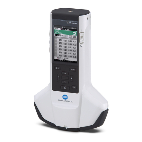
  9. Konica Minolta MYIRO-1 User manual

Konica Minolta MYIRO-1 User manual

1
MYIRO-1
Introduction Instruction Manual
[Rev 1.01]
KONICA MINOLTA, INC.
R&DDivision, Sensing Business Unit
ンシング事業部 開発部
2
1. System configuration
Standard accessories
3
2. Name and function of each part
Name
Explanation
①Power button
It is a button to turn the power on / off. Each time the button is pressed, the
status changes to ON and OFF.
②Measurement button
It is used for measurement.
③Status indicator
The status of MYIRO - 1 is displayed.
Indicates states such as measurable, scan success / failure, errors, etc. with
color and blinking.
④Network indicator
Indicates the connection status of the wireless LAN.
⑤Battery indicator
Indicates the battery status of the battery remaining capacity and charging.
⑥USB connection terminal
It is used to connect MYIRO-1 and PC with USB cable. Besides communication
with the PC, it is also used for charging.
⑦White calibration cap
It is used for calibration. When calibrating, attach it to the measurement
opening.
⑧Measurement opening
It is an opening for measuring the sample.
⑨Tripod screw hole
It is a screw for fixing a commercially available tripod. It is used for display
measurement.
4
3. Attaching / removing the ambient light attachment
Used for ambient light measurements.
How to install
1 You can install the ambient light
attachment by turning the ▲ mark in the
right figure in the direction of the arrow.
How to uninstall
2 You can uninstall the ambient light
attachment by turning the ▲ mark in the
right figure in the direction of the arrow.
5
4. Charging method
It charges by connecting to a PC or a commercially available USB-AC adapter with a USB cable.
The remaining amount and state of charge of the built-in lithium-ion battery are indicated by the battery
indicator as follows.
Indicator status
Status
Explanation
Supplementary explanation
No light
Enough
battery
power
Built-in lithium-ion batteries have
sufficient power and can be
measured.
Approximately 670 scan
measurements are possible from
the fully charged state.
If you leave after turning on the
power, the power will run out in
about 2 hours.
Blinking(Dark
orange)
Low
battery
level
Battery level is low. Although you can
measure for a while, we recommend
charging.
Approximately more than 50
scanning measurements can be
done after flashing begins.
Lighting up(Dark
orange)
Charging
Battery is charging.
It will be fully charged in about 2
to 3 hours with the power off
status.
5. Power ON / OFF
Pushing the power button from the OFF state turns on the power.
Pushing the power button from the ON state turns off the power.
6. Auto power off function
MYIRO-1 has “auto power off” function, and when communication doesn’t operate for a certain period of time,
the power turns off automatically.
To turn on the power again, press the power button. At this time, the connection with the application is
disconnected and the calibration data is deleted, so it is necessary to reconnect with the application and
recalibrate.
7. Connecting to PC
Connection with PC has USB connection and wireless LAN connection.
When using USB connection, connect MYIRO-1 and PC with USB cable.
In the case of wireless LAN connection, connection work with the initial setting tool is necessary at first
connection. Please look at the instruction manual of the initial setting tool.
The second and subsequent times are automatically connected to the network under the conditions set above.
If both USB and wireless LAN are connected, priority is given to USB connection.
If you disconnect the USB cable, it will be connected via wireless LAN.
6
8. Calibration
There are the following types of calibrations, but in either case the work in MYIRO-1 is the same.
For Chart measurement
For Ambient light measurement
For Display measurement
Procedure
8-1 Attach the white calibration cap to the measurement opening.
Before mounting the cap)
How to attach) Align the line of the main body and the line of the calibration cap (hereinafter, gray line) and
rotate it in the direction of the arrow described on the calibration cap.
7
After mounting the cap)
Note:When not using the measuring instrument, keep it with the calibration cap attached to prevent dust
adhesion.
Reference) At the time of measurement, the calibration cap can be stored as shown below.
8
8-2White calibration is performed by measurement button or control from SDK.
When white calibration is performed, the status indicator changes as follows depending on the calibration
status.
Status indicator
Status
Explanation
Supplementary
explanation
Lighting up(Yellow)
Uncalibrated
In uncalibrated condition,
calibration is necessary to
measure.
Blinking light blue
During
calibration
Calibration is in progress.
After blinking light blue (during
calibration), green lighting
(calibration success)
Successful
calibration
The calibration was
completed correctly.
After that, the state
becomes automatically
measurable.
After blinking light blue (during
calibration), dark orange
lighting (calibration failure
Calibration
failure
The calibration failed. It is
necessary to recalibration in
the correct way.
After that, it is
automatically
uncalibrated.
After successful calibration,
lights up(Blue).
Measurable
Measurement is possible.
9
9. Scanning measurement
Set the ruler on the chart so that the △ mark(Red arrow in the figure) of the ruler matches the left edge of the
chart.
Set MYIRO - 1 to the left edge of the ruler. The scan operation needs to start from the paper white part.
If you keep pushing the measurement button and the status indicator changes from blue to white, slide
MYIRO - 1 as it is. After measuring, release the button and the measurement is over. Please slide at a
constant speed as much as possible, in about 3 to 5 seconds from the edge of the ruler to the end.
Scanning is possible from the right or from the left. Regardless of which way you operate, the data will be
output from left to right.
When measuring, the status indicator changes as follows depending on the condition.
Indicator status
Status
Explanation
Supplementary explanation
Lights up(Blue)
Measurable
Measurable.
Lights up(Blue)
→Lights up(White)
Scannable
Start sliding after this state
(White lit).
If you start the slide earlier,
a measurement error will
result.
Lights up(White)
During scanning
measurement
Scanning measurement in
progress
After light white (During
measurement), green
lighting (Measurement
success)
Measurement
success
Correct measurement
completed.
After that, the state
becomes automatically
measurable.
After light white (During
measurement), dark
orange lighting
(Measurement failure)
Measurement
failure
Measurement failed. Please
repeat the measurement in
the correct way.
After that, the state
becomes automatically
measurable.
Measurement range
10
10. Spot measurement
Adjust the spot target of the ruler to the part to be measured.
Place the measurement opening of MYIRO-1 so that it meets the spot target, and perform measurement with
the measurement button or control from the SDK.
11. Ambient Light Measurement
With the ambient light attachment attached, perform measurement with the measurement button or control
from the SDK.
12. Display measurement
Attach a commercially available tripod to the tripod screw of MYIRO - 1 and set the MYIRO - 1 so that the
measurement opening faces the display to be measured at a distance of about 5 to 30 mm.
Measurement is performed by measurement button or control from SDK.
11
13. Specification
①MYIRO-1 specification
Model
Spectrophotometer
Illumination
45°a: 0° (45/0 ring illumination)
Conforms to DIN5033 Teil7、JIS Z 8722 Condition a、ISO7724/1、CIE
No.15、ASTM E 1164、ISO13655
Spectral separation device
Concave diffraction grating
Wavelength range
380 to 730nm (Ambient light measurement, Display measurement:
360-730 nm)
Wavelength pitch
10nm(Ambient light measurement, Display measurement: 5 nm)
Half bandwidth
Approx.10nm
Measurement area
φ3.5mm
Light source
LED
Measurement range
Density:0.0D to 2.5D Reflectance:0 to 150%
Short-term repeatability
Colorimetric:Within δ⊿E00 0.05
*When the white calibration plate is measured 30 times at 10 second
intervals after white calibration
Inter-instrument agreement
Within ⊿E00 0.3
*Average of 12 BVRA Series Ⅱ color tiles compared to values
measured with a master body under Konica Minolta standard conditions
Measurement time
Spot Measurement:Approx. 1 second
Scan Measurement: Approx.1 second (Press the measurement button
and then start scanning)
Approx. 1 second (From end of scan to result display (with indicator
display)
Measurement conditions
M0(A)、M1(D50)、M2(A+UV cut、C、ID50、D65、ID65、F2、F6、F7、
F8、F9、F10、F11、F12、User-defined illuminant
Display
Status indication by LED
Data memory
None
Interface
Wireless LAN(802.11 b/g/n)
USB2.0
Scanning measurements
Scan measurement of color chart is possible (It is possible to acquire color
value of all illumination conditions with one scan.)
Power
USB bus power、Rechargeable internal battery
Dimensions(D×W×H)
171mm × 73mm × 71mm
Weight
Approx. 340g
12
Operating
temperature/humidity range
10 to 35℃、30 to 85% relative humidity with no condensation
Storage
temperature/humidity range
0 to 45℃、0 to 85%relative humidity with no condensation
②Chart specification
Item
Specification
Supplementary explanation
Chart
Scanning range
270 ㎜
Maximum chart width
(Measurablerange)
257 ㎜
Scan measurement should
start with paper white and end
with paper white
Paper color
Anything is possible
The color difference between
patches at both ends must be
ΔE*ab > 10
Item
Specification
Supplementary explanation
Patch
Scanning direction
7㎜
Perpendicular
direction
7㎜
Color difference
between patches
ΔE*ab >10
If color difference is small, put a gap
between patches
Gap condition
1 line or black and white
doublet
Scanning range: 270mm
Measurable range: 257mm
Please do not print this range because paper part
which is not printing is necessary for measurement.
13
Item
Specification
Supplementary explanation
Gap
Gap Condition
1 line or black and white
doublet
Color difference
between gap and
patch
Color difference from one
patch
ΔE*ab >20
There is no problem in black and
white double lines.
Gap width
0.5 to 1.0 ㎜
③Scan condition
Item
Specification
Supplementary explanation
Scanning
speed
Patch width:7㎜
54 to 154 ㎜/s
It is determined from the number of
required data per patch
Patch width:10
㎜
54 to 208 ㎜/s
Scan direction
There is no difference in
either direction
Detect scanning direction, and
output data from left to right
Scanning direction
n
Perpendicular
directionn
Black gap
White gap
Scan direction
14
Revision history
Date
Rev.
Revised content
2019/05/20
1.00
First edition
2019/05/23
1.01
8.Calibration (Add description of calibration cap)

Other Konica Minolta Measuring Instrument manuals
Konica Minolta CR-10 Plus User manual

Konica Minolta

Konica Minolta CR-10 Plus User manual

Konica Minolta CS-2000 User manual

Konica Minolta

Konica Minolta CS-2000 User manual

Konica Minolta Vivid VI-910 User manual

Konica Minolta

Konica Minolta Vivid VI-910 User manual

Konica Minolta SPECTRAMAGIC NX - User manual

Konica Minolta

Konica Minolta SPECTRAMAGIC NX - User manual

Konica Minolta SPAD-502 User manual

Konica Minolta

Konica Minolta SPAD-502 User manual

Konica Minolta CM2500C User manual

Konica Minolta

Konica Minolta CM2500C User manual

Konica Minolta SKR 4000 User manual

Konica Minolta

Konica Minolta SKR 4000 User manual

Konica Minolta CM3600D User manual

Konica Minolta

Konica Minolta CM3600D User manual

Konica Minolta REGIUS SIGMA2 User manual

Konica Minolta

Konica Minolta REGIUS SIGMA2 User manual

Konica Minolta AeroDR System User manual

Konica Minolta

Konica Minolta AeroDR System User manual

Konica Minolta CR-10 User manual

Konica Minolta

Konica Minolta CR-10 User manual

Konica Minolta VI-9I User manual

Konica Minolta

Konica Minolta VI-9I User manual

Konica Minolta CS-7 User manual

Konica Minolta

Konica Minolta CS-7 User manual

Konica Minolta CM-25cG User manual

Konica Minolta

Konica Minolta CM-25cG User manual

Konica Minolta CA-410 Series User manual
Konica Minolta

Konica Minolta CA-410 Series User manual

Konica Minolta CM-36dGV User manual

Konica Minolta

Konica Minolta CM-36dGV User manual

Konica Minolta VIVID 9i/VI User manual

Konica Minolta

Konica Minolta VIVID 9i/VI User manual

Konica Minolta CR-10 Plus User manual

Konica Minolta

Konica Minolta CR-10 Plus User manual

Konica Minolta CECF-9 User manual

Konica Minolta

Konica Minolta CECF-9 User manual

Konica Minolta CM-3600D User manual

Konica Minolta

Konica Minolta CM-3600D User manual

Konica Minolta CA-100PLUS User manual

Konica Minolta

Konica Minolta CA-100PLUS User manual

Konica Minolta REGIUS 110 HQ User manual

Konica Minolta

Konica Minolta REGIUS 110 HQ User manual

Konica Minolta CM-600d User manual

Konica Minolta

Konica Minolta CM-600d User manual
Konica Minolta bizhub C3100i User manual

Konica Minolta

Konica Minolta bizhub C3100i User manual

Popular Measuring Instrument manuals by other brands

Megger IDAX 300 user guide

Megger

Megger IDAX 300 user guide

Kingspan TMS300 MULTI-TANK CS User and installation manual

Kingspan

Kingspan TMS300 MULTI-TANK CS User and installation manual

Brooks Glass Tube Full-View 1110 Operation manual

Brooks

Brooks Glass Tube Full-View 1110 Operation manual

Pentax R-422VN instruction manual

Pentax

Pentax R-422VN instruction manual

Keysight U1211A quick start guide

Keysight

Keysight U1211A quick start guide

Maxim MAX16067 manual

Maxim

Maxim MAX16067 manual

Reed Instruments R5020 instruction manual

Reed Instruments

Reed Instruments R5020 instruction manual

Patlite NH-FV Series instruction manual

Patlite

Patlite NH-FV Series instruction manual

ELTRA CS-i operating manual

ELTRA

ELTRA CS-i operating manual

Farringdon RCA5 Series Installation and operating instructions

Farringdon

Farringdon RCA5 Series Installation and operating instructions

Vernier VRM-BTD quick start guide

Vernier

Vernier VRM-BTD quick start guide

CGEO INTERNATIONAL LIMITED CGEO-CR installation manual

CGEO INTERNATIONAL LIMITED

CGEO INTERNATIONAL LIMITED CGEO-CR installation manual

TeeJet Tankmatic user manual

TeeJet

TeeJet Tankmatic user manual

Onicon F-5000 Installation and operation guide

Onicon

Onicon F-5000 Installation and operation guide

Robit M Sense Operator's manual

Robit

Robit M Sense Operator's manual

Interacoustics AA222 Instructions for use

Interacoustics

Interacoustics AA222 Instructions for use

Huawei SmartLogger1000 quick guide

Huawei

Huawei SmartLogger1000 quick guide

entegris InVue CR288 user guide

entegris

entegris InVue CR288 user guide

manuals.online logo
manuals.online logoBrands
  • About & Mission
  • Contact us
  • Privacy Policy
  • Terms and Conditions

Copyright 2025 Manuals.Online. All Rights Reserved.