I304 GB RO 01 15 31100138
1
DME D100 T1 MID
WARNING!
–Carefully read the manual before the installation or use.
– This equipment is to be installed by qualified personnel, complying to current standards, to avoid damages or safety hazards.
–Remove eventual dangerous voltage from the product before any maintenance operation on it.
– The manufacturer cannot be held responsible for electrical safety in case of improper use of the equipment.
– Products illustrated herein are subject to alteration and changes without prior notice. Technical data and descriptions in the
documentation are accurate, to the best of our knowledge, but no liabilities for errors, omissions or contingencies arising
therefrom are accepted.
–A circuit breaker must be included in the electrical installation of the building. It must be installed close by the equipment and
within easy reach of the operator.
It must be marked as the disconnecting device of the equipment: IEC /EN 61010-1 § 6.11.2.
– Fit the instrument in an enclosure or cabinet with minimum IP51 degree protection.
–Clean the instrument with a soft dry cloth, do not use abrasives, liquid detergents or solvents.
INTRODUCTION
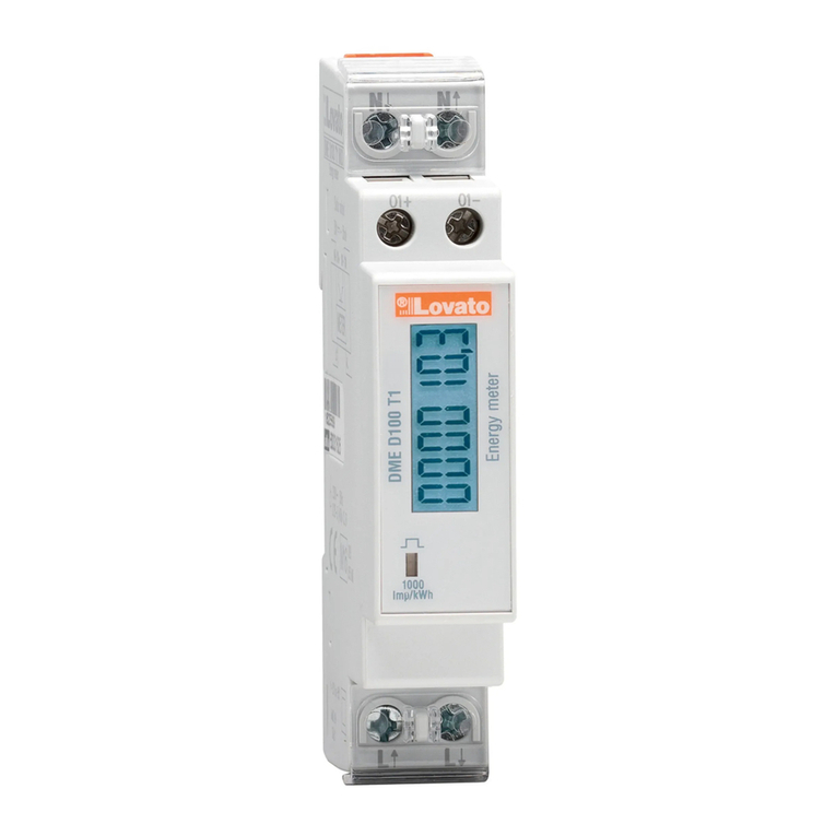
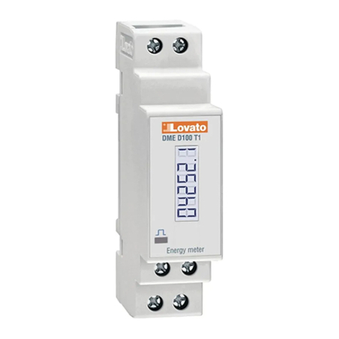
The DME D100 T1 is a single-phase active and reactive energy meter for direct connection, for currents up to 40A.
The energy accuracy is compliant with EN 50470-3 (MID class B).
The DME D100 T1 has a standard 1U (18mm wide) modular housing and is supplied with sealable terminal blocks.
DESCRIPTION
– Modular DIN-rail housing, 1U (18mm wide).
–Direct connection for currents up to 40A.
– Total active energy metering complies EN 50470-3 class B.
–Available in standard version (code DMED100T1) and in MID-certified version (code DMED100T1 MID).
–LCD display with 5+1 digits counter.
–Pulse LED for active energy consumption.
– Static pulse output for remote energy counting.
METROLOGICAL LED
–The red LED on the front emits 1000 pulses for every kWh of consumed Energy (that is, one pulse every Wh).
– The pulsing frequency of the LED gives an immediate indication of the energy flowing in every moment.
– The pulse duration, LED colour and intensity are compliant with the reference standards that define its utilization in order to
verify the accuracy of the energy meter.
INSULATED STATIC OUTPUT
–The static output on the upper terminals sends 10 pulses per kWh.
–It can be used as a pulse output for remote energy counting towards:
•
An external data concentrator (like DME CD)
•
A remote electromechanical counter
•
A PLC or other device
– The connection can be done in PNP or NPN mode. See schematic diagrams and technical characteristics for details on the
wiring and on the rating.
INCORRECT WIRING INDICATION
– In case of incorrect wiring, when the device detects a reverse energy flow, the display shows the blinking code Error 3.
– This error is caused by either reverse connection of current wires (terminals L↑and L↓) or reverse voltage wiring (terminals
N - L↑).
–In these conditions the energy is not counted.
METROLOGICAL SEALING AND MAR INGS
– The MID certified device is identified by the appropriate markings on the side (see picture) and by the product code DME D100
T1 MID written on the front panel and on the side of the enclosure.
– It is equipped with some anti-tampering solutions like:
•
Two anti-tampering labels that seals the enclosure, that avoid the possibility to access the internal circuitry.
•
Sealable terminal covers that, when installed with proper sealing eliminate the possibility to access terminals and wiring
– The sealings on the device must appear intact, otherwise the MID certification is void.
– The serial number of the device is placed on a label on the side.
METROLOGICAL SEALING AND MAR INGS
– The MID certified device is identified by the appropriate markings on the side (see picture) and by the product code DME D110
T1 MID written on the front panel and on the side of the enclosure.
– It is equipped with some anti-tampering solutions like:
•
Two anti-tampering labels that seals the enclosure, that avoid the possibility to access the internal circuitry.
•
Sealable terminal covers that, when installed with proper sealing eliminate the possibility to access terminals and wiring
– The sealings on the device must appear intact, otherwise the MID certification is void.
– The serial number of the device is placed on a label on the side.
AVERTIZARE!
–Citiţi cu atenţie manualul înainte de instalare sau utilizare.
–Acest echipament va fi instalat de personal calificat, în conformitate cu standardele actuale, pentru a evita deteriorări sau pericolele.
–Îndepărtai tensiunea cu potenial periculos de la produs înainte de a efectua orice fel de aciuni de întreinere.
–Producătorul nu poate fi considerat responsabil pentru siguranţa electrică în caz de utilizare incorectă a echipamentului.
–Produsele ilustrate în prezentul sunt supuse modificărilor şi schimbărilor fără notificare anterioară. Datele tehnice şi descrierile din
documentaţie sunt precise, în măsura cunoştinţelor noastre, dar nu se acceptă nicio răspundere pentru erorile, omiterile sau
evenimentele neprevăzute care apar ca urmare a acestora.
–Trebuie inclus un disjunctor în instalaţia electrică a clădirii. Acesta trebuie instalat aproape de echipament şi într-o zonă uşor
accesibilă operatorului. Trebuie marcat ca fiind dispozitivul de deconectare al echipamentului: IEC /EN 61010-1 § 6.11.2.
–Montai instrumentul într-un locaș închis sau într-un dulap cu protecie minimă de grad IP51.
–Curăţaţi instrumentul cu un material textil moale şi uscat; nu utilizaţi substanţe abrazive, detergenţi lichizi sau solvenţi.
INTRODUCERE
DME D100 T1 este un contor de energie activa si reactiva și cu fază unică pentru conectarea directă pentru curent de până la 40A.
Precizia energetică respectă EN 50470-3 (MID clasă B).
DME D100 T1 are carcasă standard modulară 1U (18mm lăime) și se livrează cu blocuri terminale sigilabile.
DESCRIERE
–Carcasă modulară pe șină 1U (18mm lăime).
–Conexiune directă pentru curent de până la 40A.
–Măsurarea energiei active totale respectă EN 50470-3 clasa B.
–Disponibil în versiune standard (cod DMED100T1 ) și în versiune certificată MID (cod DMED100T1 MID).
–Ecran CD cu dispozitiv de măsurare cu 5+1 cifre.
–Puls ED pentru consum activ de energie.
– Ieșire puls static pentru calculare energie la distană.
ED METRO OGIC
– ED-ul roșu din faă emite 1000 de pulsaii pentru fiecare kWh de energie consumată (adică un puls la fiecare Wh).
– Frecvenţa pulsării ED-ului indică imediat fluxul de energie în orice moment.
–Durata pulsului, culoarea ED-ului și intensitate respectă standardele de referină care definesc utilizarea sa pentru a verifica
exactitatea contorului de energie.
IEȘIRE STATICĂ IZO ATĂ
– Ieșirea statică de pe bornele superioare trimit 10 pulsaii/kWh.
–Se poate folosi ca ieșire de pulsaii pentru măsurarea energiei la distană către:
•
Concentrator de date extern (precum DME CD)
•
Un sistem de măsurare electro-mecanic la distană
•
Un P C sau alt dispozitiv
– Conexiunea se poate face în modul PNP sau NPN. Vezi diagrame schematice și caracteristici tehnice pentru detalii privind cablarea și
caracteristicile nominale.
INDICAIE INCORECTĂ CAB ARE
– În de cablare incorectă, dispozitivul va indica codul intermitent Error 3 în cazul în care dispozitivul detectează flux de energie
inversată.
– Eroarea este cauzată fie de conexiune inversă a firelor de curent (borne L↑ și L↓)fie de cablarea inversă a voltajului (borne N - ↑).
– În aceste condiii nu se măsoară energia.
SIGI ARE ȘI MARCAJE METRO OGICE
– Dispozitivul certificat MID se identifică în funcie de marcajele adecvate de pe partea laterală (vezi imagine) și după codul de produs
DME D100 T1 MID scris pe panoul frontal și pe partea laterală a locașului.
– Este echipat cu câteva soluii anti-furt precum:
•
Două etichete anti-furt care sigilează locașul prin care se evită posibilitatea accesării circuitelor interne.
•
Înveliș sigilabil pentru bornă care odată instalat cu sigilare adecvată elimină posibilitatea de a accesa bornele și cablurile.
– Sigiliile de pe dispozitiv trebuie să fie intacte altfel certificarea MID nu mai este valabilă.
– Numărul de serie al dispozitivului se află pe o etichetă în interior.
SIGI ARE ȘI MARCAJE METRO OGICE
– Dispozitivul certificat MID se identifică în funcie de marcaele adecvate de pe partea laterală (vezi imagine) și după codul de produs
DME D110 T1 MID scris pe panoul frontal și pe partea laterală a locașului.
– Este echipat cu câteva soluii anti-furt precum:
•
Două etichete anti-furt care sigilează locașul prin care se evită posibilitatea accesării circuitelor interne.
•
Înveliș sigilabil pentru bornă care odată instalat cu sigilare adecvată elimină posibilitatea de a accesa bornele și cablurile.
– Sigiliile de pe dispozitiv trebuie să fie intacte altfel certificarea MID nu mai este valabilă.
– Numărul de serie al dispozitivului se află pe o etichetă în interior.
S ngle-phase d rect connect on energy meter
Instruct on manual
GB
Contor de energie cu cone iune directă
Manual de utilizare
RO
LOVATO ELECTRIC S.P.A.
24020 GORLE (BERGAMO) ITALIA
VIA DON E. MAZZA, 12
TEL. 035 4282111
TELEFAX (Nazionale): 035 4282200
TELEFAX (International): +39 035 4282400
E-mail info@LovatoElectric.com
Web www.LovatoElectric.com
Capace borne sigilabile
Sigilare metrologică
Capace borne sigilabile
MECHANICAL DIMENSIONS [mm] AND WIRING DIAGRAMS
63
90
45
98.3
104.7
17.9
43.7
Ø4.2mm
DIMENSIUNI MECANICE [MM] ȘI DIAGRAME CABLAJ
LL
SO+
N
SO-
N
LL
SO+ SO-
NN
N
SO+
LL
SO-
N
O1-O1+
Static output
30VDC 50mA max
_
+
NN
LL
LOAD
LINE
NPN out PNP out
