manuals.online logo
Brands
  1. Home
  2. •
  3. Brands
  4. •
  5. Haier
  6. •
  7. TV
  8. •
  9. Haier L40A8A-A1 User manual

Haier L40A8A-A1 User manual

L40A8A-A1
Contents
1. Summarize
2. Main features
3. Appearance picture of complete set
4. Chassis appearance picture
5. Interface definition and interface electric requirements
6. Factory mode instructions
7. Structure size
8. The requirements of transportation, storage and usage
9. Appendix
1. Summarize
this chassis is used to match and connect the big screen LCD TV, it supports multi-system TV input signal ,
it can stored 128 TV programs at most, at the same time the highest resolution of this chassis can be up to
SXGA or appear R, G, B input signal of WXGA of 16:9 again, color appear again can support 24 bit, and it
can realize synchronous automatic check. It can support 1080P HD signal input at most, and includes two
rows CVBS signal, one row S terminal signal input, one row HDMI signal one row CVBS signal output.
Inbuilt 2x10W medium sound + 2x3W treble sound output, four rows two channels external audio signal
input, one row sound output. Support left and right sound balance, equalizer adjustment function.
Meanwhile, this chassis can support TV signal and digital display in HD signal at the same time, and there are
3A picture optimise, 3A demo.
2. Main Features
LCD TV control panel support specifications:
Input/Output signal
Analog RHB(0.7Vp-p)
Composite Video Signal(1.0Vp-p +/-5%)
TV Video
Four rows two rows external audio input(PC sound
effect card and AV equipment sound input)
Video support system PAL: NTSC(AV)
TV receiving band VHF-L:49.75-160.25MHz
VHF-H:168.25-450.25MHz
UHF:451.25-863.25MHZ
Support Mode VGA, SVGA, XGA, SXGA , WXGA
Color 24bit
H-synchronous range 30-70KHz
V-synchronous range 56-75Hz
Output signal LVDS standard
Audio Output power 2Χ10WΧ
Control button TV/AV, VOL-, VOL+, POWER, CH-, CH+, MENU
(All the function can be operated by remote
controller)
OSD menu VGA: picture screen sound route function menu
TV: picture sound route function menu
OSD language English
Power input 150-240V(AC)
Power operations Normal working mode, standby mode
Power consumption 140W (without load)
Plug and play function Support
Power manage Standby Power consumption
3. Appearance picture of complete set
The sound box part and the structure of complete set is separable,so it need install solely.
4. Appearance picture of chassis
5. Interface definition (see appendix 2) and interface electric requirements
1. Power interface: supply the working power to chassis from power board..
2. Background light control panel interface: control the switch and brightness of screen background light
S-VIDEO input
PC audio input
VGA input
Power input
socket
Key control
socket
Screen connecting
Wire socket
Background light
control interface
Up grading
socket
CVBS input
AV1video input
AV video output
Speakeroutput
Remote control
socket
(down)HD signal input
AVaudio output
AV1audio input
HD signal audio input
Earphone socket
The speaker power socket
HDMI input
Side AVsocket
3. Remote control interface: support Toshiba receiving negotiation.
4. Control panel interface: 7 button control.
5. Sound output interface: sound signal output.
6. Program upgrading interface: upgrading program. Only for factory use.
6. Factory mode instructions
This chassis use new HYF-35R remote controller (grey, 41 button, can not share with the original blue 35
button HYF-35R ), the method to enter the factory mode is: Screen-----P.STD------S.STD------Sleep Time.
The following is the instructions of the factory menu of V2.1 version program
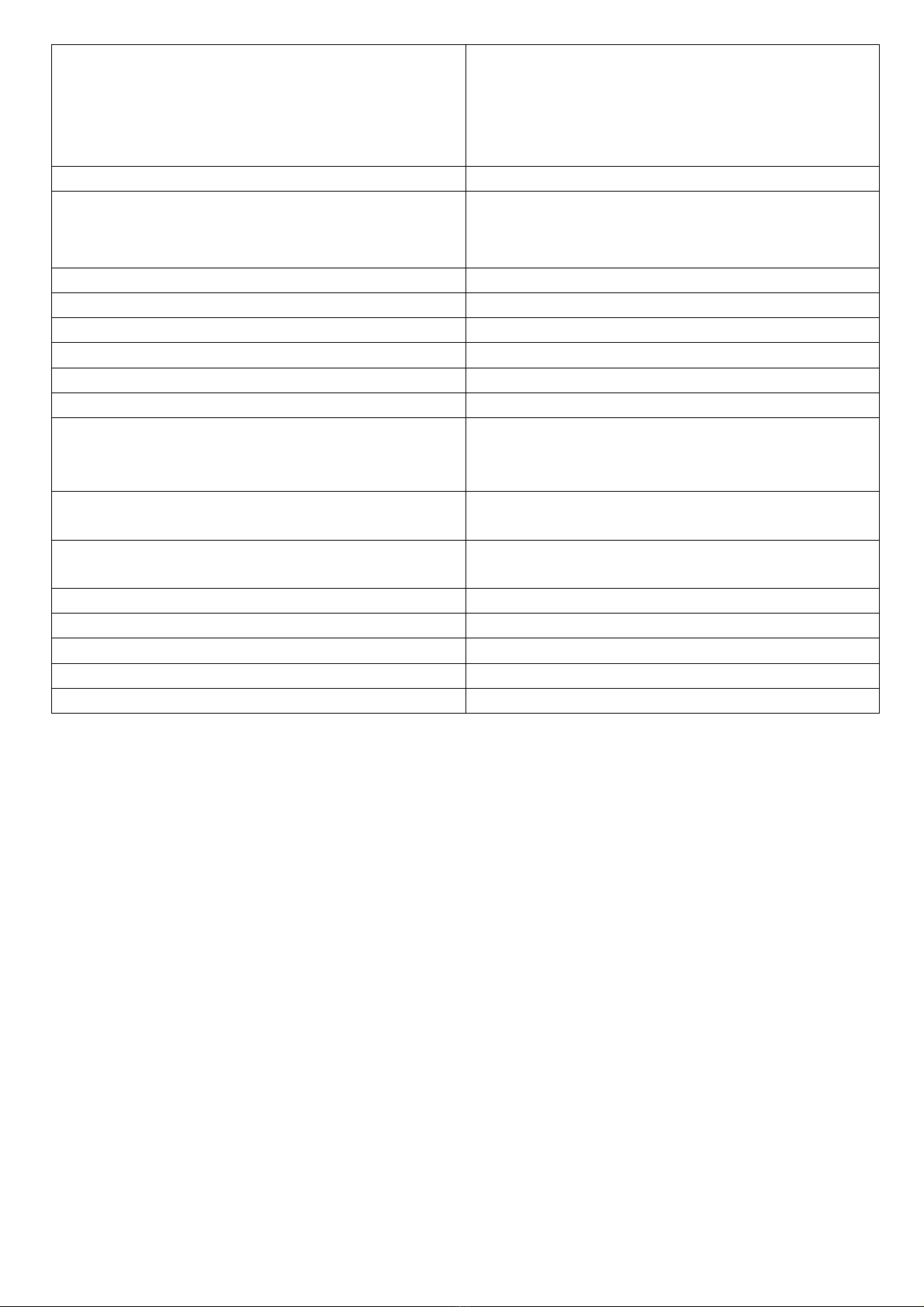
. DEBUG MENU.
Name Description
P.STD
S.STD
VOL SET
PICTURE MODE ADJUST
SOUND MODE ADJUST
VOLUME ADJUST
SAVE MODE
M.CLK
AGC
NO SET
DDRAM SET
AGC ADJUST
ENABLELOGO ON: open OFF: close
E2P SET ADJUST the DATA of EEPROM
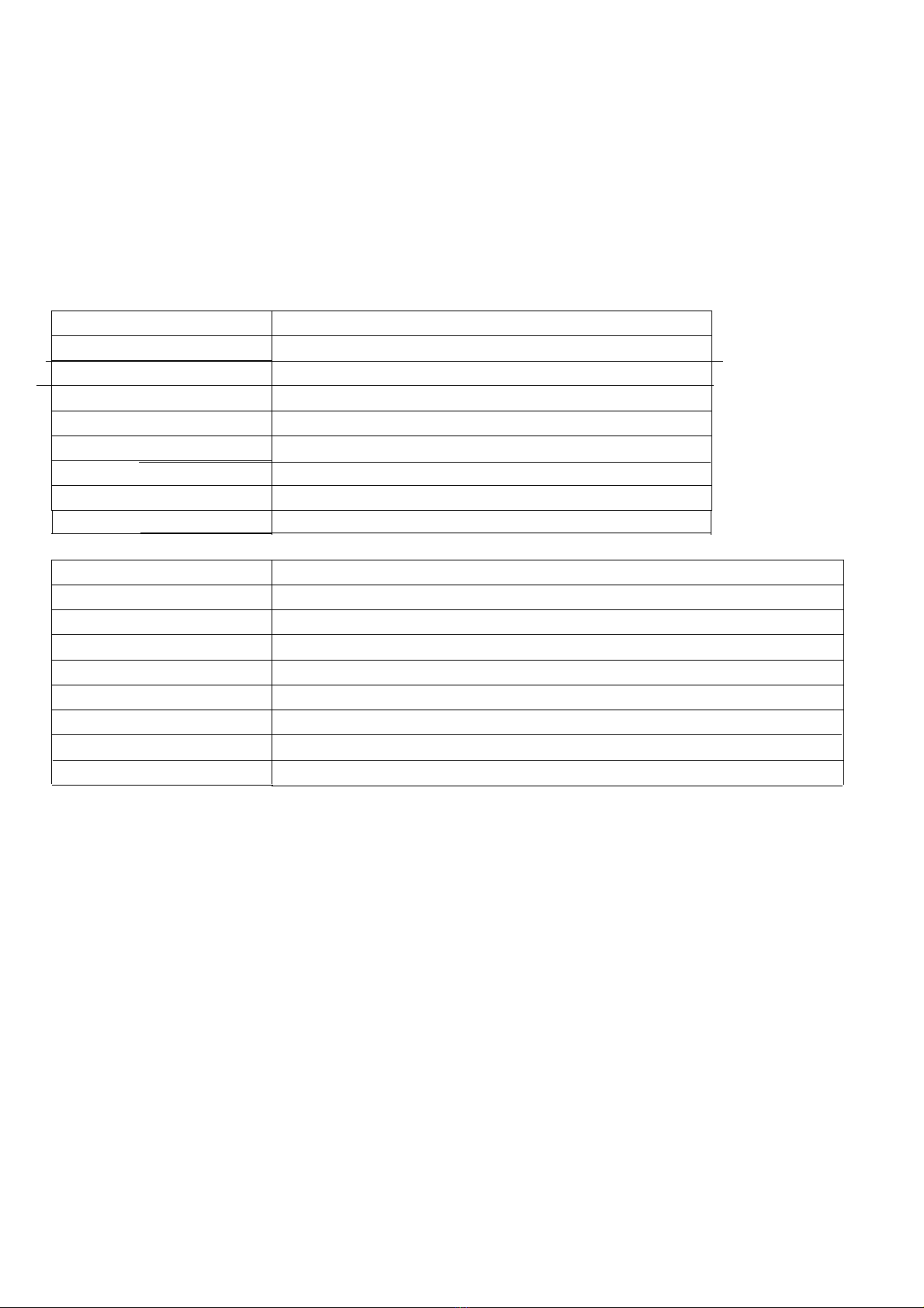
FAC.MENU
Name Description
PWR. STB ON: power standby OFF: standby memory
ENABLELOGO Screen saver without signal ON: open OFF: close
TEST PAT. picture test
TV INIT Initialised factory signal do not use
E2P INIT Initialize EEROM
VERSION software property
BUS-SEL open or close BUS
WHITE BLC White blance adjust
Never adjust the following other items
7. Structure dimension (see appendix 1)
Relevant dimension specifications of control panel PCB,The specification of screw hole: diameter 3.3mm
screw hole , the structure diagram of hole position
8. Transportation, storage and usage requirements
1. Never press heavily and bend
2. Eliminated static
3. Relative humidity: below 80%
4. Storage temperature: -10¬+40℃
5. Usage temperature: 0¬+40℃
9. Appendix
Appendix 1: the dimension diagram of structure
Appendix 2: interface definition table
XP600 (9PIN/2.5): Power interface
NO. Definition Description
1 STN Power-on signal(high-level is available)
2 GND Ground
3 5V CPU working voltage(standby but not power
off)
4 GND Ground
5 GND Ground
6
7
8
9
GND
12V
12V
12V
Ground
Chassis working power (standby but power off)
XP601 XP601A (3PIN/2.0):Background light control interface
NO. Definition Description
1 ADJ Background light brightness control
2 ON/OFF INVERTER ON/OFF (high level is
available )
3 GND Ground
XP501(4PIN/2.0): Remote control button interface
NO. Definition Description
1 IR Remotecontrolreceiving
2 +5V 5VPower
3 GND Ground
4 LED Powerindicatorcontrol
XP502(4PIN/2.0):
NO. Definition Description
1 KEY1 Control panel signal 1
2 GND Ground
3 KEY0 Controlpanelsignal2
4 GND Ground (air connect)
XP301 (Right sound), XP302 (left sound) (2PIN/2.5): Sound output interface
NO Definition Description
1 SPK+ Sound output signal +
2 SPK- Sound output signal -
XP503 (4PIN/2.5):
NO. Definition Description
1 5V CPU Power
2 GND Ground
3 RXD Signal interface
4 TXD Signal interface
L40A8A-A1
Drafted by:Chen Long Checked by:Peng You Approved by:Hu Xijia
User’s Manual
①
NO Power
Check power board 24V supply See background light is not on partCheck power board 12V supply
CPU is damaged replace
Check power board 5V supply
Check CPU Power-on signal
Check power boardAC input
Power boad is damaged,replace
Check and repair Power input part
with
with
with
with
with
without
without
without
without
without
②
Video Without Signal
TV Without
Check tuner 5V supple
Check if the bus control is normol
Check if the tuner is output
Check if the signal is input the
picture decode chip
Check if the chip supple,crystal
osciuator or bus control is normal
Chip is damaged,replace
Check and repair 5V supple part
Deck and repair bus control part
Tuner is damaged,replace
Check and repair if the signal
circuit is erroneous
Check an repair the chip relevant
circuit
with
without
Yes
Yes
Yes
Yes
Yes
No
No
No
No
③
Background is not/Background is
always on
Check the power board 24Vsupply
Check and repair logic control
circuit
Connect the wire cluster again
Check it on/standly CPUbackground
light control pin is changed Check and repair CPU relevant
circuit
Power board is damaged, replace
Check it inverter background
light control pin is changed
Check it connecting wire is loosen The screen is damaged,replace
Always on
Not on
with
with
with
with
without
without
without
without
④
white screen / flower screen
/absent color /little color
check if lvds wire is loosen
white screen
check if the control circuit
is normal
check if the supply circuit
is normal
check if the supply circuit
is normal
connect LVDS wire again
flower screen /absent color
/little color
The screen is damaged ,
replace
Check and repair logic
circuit or CPU
Check and repair power
circuit
Check if the interface of
signal output is linking
soldered Solder again
Check if the MST6151 chip
is working normal
Check and repair chip
working circuit
Yes
Yes
Yes
Yes
No
No
No
No
No
No
Yes
with
ih
without
with
with
with
without
ih
without
Check sound amplifying
circuit
with
Check and repair 4052
relevant circuit
AV1、AV2 output without
sound
Check if the acoustics is
trouble
Connecting wire cluster
again
HD、VGA、AV2
without sound
Check if the connecting
wire cluste
r
a
g
ain
TV without sound
Check and repair sound
am
p
lif
y
in
g
circuit
Check and repair MSP3410
relevant circuit
Replace、check acoustics
part
Check and repair terminal Check if the terminal is
linking soldered or damaged
Check if the terminal is
linking soldered or damaged
Check 4052 relevant circuit Check MSP3410 relevant
circuit
Check if thehorn wire or
wire clamp is damaged Replace the horn wire、wire
clamp
with
ih
with
with
with
5
1 2 3 4 56
A
B
C
D
6
54321
D
C
B
A
Title
Number RevisionSize
B
Date: 6-Jan-2007 Sheet of
File: E:\陈龙\LCD\MSTAR\MST9X88\设计文件\PCB\PCB-bak\PY12038-----Q(V1.0).DDBDrawn By:
+
CA107
470uF/35V L90
FB
+12V
C4
0.1u +
CA108
470uF/16V
+5V
C3
0.1u
D5
SR34
+5V
5Vstb1
5Vstb
5Vstb
R338
4.7K
R337
10K
Q34
3904
5Vstb1
1
2
3
4
5
6
7
8
9
XP600
CON9
POWER-ON/OFF1
+12V
POWER-ON/OFF
+3.3AVDD
gnd
1
out 2
in
3tab/out 4
U5
AMS1117-3.3
+
CA15
100uF/16V C21
0.1u
+CA16
100uF/16V
C22
0.1u
+
CA14
100uF/16V
L12
10uH
5Vstb
C20
0.1u
AVDD_HDMI
C287
0.1u
+
CA17
2.2uF/16V
L13
3.3uH
+3.3AVDD
C23
0.1u
AVDD_AU
+
CA141
22uF/16V
L22
10uH
+3.3AVDD
C386
0.1u
AVDDA
+
CA27
22uF/16V
L23
10uH
+3.3AVDD
C58
0.1u
AVDD_SIF
+
CA142
22uF/16V
L19
10uH
+3.3AVDD
C385
0.1u
AVDD_MemPLL
L18
FB
+3.3AVDD
C47
0.1u
C46
1u/16V C48
0.1u
VDD_MPLL
L27
FB
+3.3AVDD
C381
0.1u
C380
390p C382
2.2u C383
390 C384
0.1u
+2.5MVDD
+
CA22
22uF/16V
L17
600(4.5X3.2)
+2.5VM
C35
0.1u
+
CA29
22uF/16V
L25
600(4.5X3.2)
+2.5VM
C389
0.1u
+2.5V_DMC
+2.5VM
gnd
1
out 2
in
3tab/out 4
U8
AMS1117-2.5
+
CA18
47uF/16V C24
0.1u
+CA19
100uF/16V
C25
0.1u
5Vstb
+8V
+
CA58
47uF/16V C111
0.1u
+CA59
100uF/16V
C112
0.1u
+12V
VOUT 3
VIN
1
GND
2
U18
LM7808
VDDP
C56
0.1u
C55
0.1u C57
0.1u C31
0.1u C32
0.1u
C53
0.1u
C52
0.1u
C54
0.1u
+
CA23
100uF/16V
L16
600(4.5X3.2)
+3.3V
C45
0.1u
+3.3V
5Vstb
gnd
1
out 2
in
3tab/out 4
U7
AMS1084-ADJ
+CA24
47uF/16V
C34
0.1u
R214
1.2K
R213
2K
L15
FB
+
CA20
47uF/16V C33
0.1u
+12V
VPANEL_IN
PWM3_PANEL
PWM3_PANEL
S2
3
G2
4D2b 5
D2a 6
S1
1
G1
2D1b 7
D1a 8
U2
IRF7314
R2
10K C2
0.1u
Q1
3904
R5
4.7K
+CA5
22uF/25V
C8
0.1u
VCC-Panel
L2
600(4.5X3.2)/NC
+5V L6
600(4.5X3.2)/NC
C1
0.1u
C15
0.1u
R8
1K
R10
10K
R16
4.7K C14
1uF
Q4
3904
ADJ-PWM2
R11
1K
5Vstb
ON-PBACK
R9
10K
R13
4.7K
Q3
3904
ON-PBACK
BL-ADJUST_in
1
2
3
XP601
LCD BKL
1
2
3
XP602
LCD BKL
BL-ON/OFF
5V/GND
R7
0/NC R6
0/NC
5Vstb
ADJ-PWM2
VDDC
+3.3V
gnd
1
out 2
in
3tab/out 4
U6
AMS1084-1.8
+CA21
47uF/16V
C19
0.1u
R19
NC
R20
0
+
CA12
47uF/16V C18
0.1u
VDDC
C30
0.1u
C29
0.1u
C27
0.1u
C26
0.1u
C28
0.1u
+
CA100
470uF/35V
+5V
L96
100uH
A K
D49
IN5822
+
CA86
1000uF/16V
C281
0.1u
+12V
VIN
1FB 4
OUT 2
GND
3
TAB
6
ON/OFF
5
U30
LM2596-5
C5
0.1u
PANEL-ON/OFF R476
0/NC R478
O/NC
VDDP
BL-ADJUST_out
R4
0/NC
C40
0.1u
C39
0.1u
C37
0.1u
C36
0.1u
C38
0.1u
+2.5MVDD
+2.5V_DMQ
+
CA28
22uF/16V
L20
600(4.5X3.2)
+2.5VM
C42
0.1u
R500
1/2W-33
C802
0.1u
C803
100pF
C924
560p
L4
FB
R515
4.7K
12345678910 11 12
A
B
C
D
12
1110987654321
D
C
B
A
Title
Number RevisionSize
A1
Date: 6-Jan-2007 Sheet of
File: E:\陈龙\LCD\MSTAR\MST9X88 \设计文件\PCB\PCB-bak\PY12038-----Q(V1.0).DDBDrawn By:
DVIRX0N
4
DVIRX0P
5
DVIRX1N
7
DVIRX1P
8
DVIRX2N
10
DVIRX2P
11
DVI_CKN
1
DVI_CKP
2
REXT
13
DDCD_SDA
14
DDCD_SCL
15
RMID
18
VCLP
19
REFP
20
REFM
21
HSYNC1
16
VSYNC2
17
BIN1P
22
BIN1M
23
SOGIN1
24
GIN1P
25
GIN1M
26
RIN1P
27
RIN1M
28
BIN0M
29
BIN0P
30
GIN0M
31
GIN0P
32
SOGIN0
33
RIN0M
34
RIN0P
35
HSYNC0
38
VSYNC0
39
VSYNC2
40
BIN2P
41
BIN2M
42
SOGIN2
43
GIN2P
44
GIN2M
45
RIN2P
46
RIN2M
47
C1
48
Y1
49
C0
50
Y0
51
VCOM2
52
CVBS3
53
CVBS2
54
CVBS1
55
VCOM1
56
CVBS0
57
VCOM0
58
CVBSO
59
AUL0
71
AUR0
72
AUL1
73
AUR1
74
AUCOM
75
AUL2
76
AUR2
77
AUL3
78
AUR3
79
AUMONO
80
BPSL
81
BPSR
82
AUOUTL
85
AUOUTR
86
AUOUTS
87
SIF0M
61
SIF0P
62
SIF1P
64
SIF1M
65
AUVRADN
67
AUVRADP
68
AUVREF
69
NC
83
NC
84
NC
88
NC
89
NC
90
NC
91
NC
92
NC
93
NC
94
NC
95
NC
96
DDCR_DA
174
DDCR_CK
175
DDCA_DA
176
DDCA_CK
177
SAR0
168
SAR1
169
SAR2
170
SAR3
171
PWM0/MCUCFG0
172
PWM1/MCUCFG1
173
PWM2/MCUCFG2
192
PWM3/MCUCFG3
193
PAD_IRIN
179
GNDA
3
GNDA
9
GNDA
37
AVSS_SIF
60
AVSS_SIF
66
GNDP
98
GNDP
163
GNDP
210
GNDP
224
GNDM
103
GNDM
111
GNDM
131
GNDM
145
GNDC
181
GNDC
243
SPI_DI
165
SPI_DO
167
SPI_CK
164
SPI_CZ
166
DIGO0
183
DIGO1
184
DIGO2
185
DIGO3
186
DIGO4
187
DIGO5
188
DIGO6
189
DIGO7
190
DIGO8
191
WRZ
159
RDZ
160
ALE
161
INT
178
MA0 136
MA1 137
MA2 138
MA3 139
MA4 140
MA5 141
MA6 142
MA7 143
MA8 147
MA9 148
MA10 149
MA11 150
BADR0 129
BADR1 128
WEZ 135
CASZ 134
RASZ 130
DQS1 100
DQS0 122
DQM 123
MVREF 124
MCLKE 125
MCLKZ 126
MCLK 127
MD15 101
MD14 102
MD13 104
MD12 105
MD11 107
MD10 108
MD9 109
MD8 110
MD7 113
MD6 114
MD5 115
MD4 116
MD3 118
MD2 119
MD1 120
MD0 121
LA4P 197
LA4M 198
LA3P 199
LA3M 200
LACKP 201
LACKM 202
LA2P 203
LA2M 204
LA1P 205
LA1M 206
LA0P 207
LA0M 208
LB4P 211
LB4M 212
LB3P 213
LB3M 214
LBCKP 215
LBCKM 216
LB2P 217
LB2M 218
LB1P 219
LB1M 220
LB0P 221
LB0M 222
GPIOE3 225
GPIOE2 226
GPIOE1 227
GPIOE0 228
ICLK/UARX0 229
IDE/UATX0 230
IHSYNC/UARX1 231
IVSYNC/UATX1 232
DI0/SPIDFO 233
DI1/AUMCKO 234
DI2/AUMUTE 235
DI3/AUWS 236
DI4/AUSCK 238
DI5/AUSDO 239
DI6 240
DI7 241
DI8/SPIDFIN 244
DI9/AIWS 245
DI10/AISCK 246
DI11/AISD 247
DI12/AISD1 248
DI13/AISD2 249
DI14/AISD3 250
DI15 251
AD0 151
AD1 152
AD2 153
AD3 154
AD4 155
AD5 156
AD6 157
AD7 158
AVDD_MemPLL 133
VDDC 242
VDDC 195
VDDC 182
VDDC 146
VDDC 99
AVDD-MPLL 256
AVDD-MPLL 194
VDDP 252
VDDP 237
VDDP 223
VDDP 209
VDDP 196
VDDP 180
VDDP 162
VDDP 97
VDDM 144
VDDM 132
VDDM 117
VDDM 112
VDDM 106
AVDD-AU 70
AVDD-SIF 63
AVDD 36
AVDD-DVI 12
AVDD-DVI 6
HERESET 253
XOUT 254
XIN 255
MST9X88LD
U9
MST9X88LD
B_TX0-
B_TX0+
G_TX1-
G_TX1+
R_TX2-
R_TX2+
TXCLK-
TXCLK+
R34
390R1%
HDMI_SDA
HDMI_SCL
C76 0.1U
C77 0.1U
C78
0.1U
C82
0.1U
C83
0.1U
AVDD_HDMI
HS_RGB
VS_RGB
BIN+
BIN-
SOG
GIN+
GIN-
RIN+
RIN-
SCB-
SCB+
SCG-
SCG+
SC_SOG
SCR-
SCR+
SC_FS
SC_FSW
VSYNC2
PB+
PB-
SOY
Y+
Y-
PR+
PR-
C84 10nF
C85 10nF
C86 10nF
C89 10nF
C90 10nF
C91 10nF
C92 10nF
C93 10nF
C94 10nF
C95 10nF
C96 10nF
SC_C1
SC_Y1
SV_C0
SV_Y0
VCOM2
TUNER_CVBS1
CVBS2
CVBS3
VCOM1
VCOM0
TUNER_CVBS
CVBSOut
S-VIDEOCin
S-VIDEOYin
USB-Cin
USB-Yin
USB-Yin-
FULL-SCART-Vin+
HALF-SCART-Vin+
TV1-Vin-
TV1-Vin+
C69 2.2u
C70 2.2u
C97 2.2u
C113 2.2u
C68 2.2u
C147 2.2u
C148 2.2u
C129 2.2u
C130 2.2u
R25
0
MUX-Lin
MUX-Rin
HD1-Lin
HD1-Rin
PC-Rin
AV2-Rin
AV2-Lin
PC-Lin AUCOM
PH-Lout
PH-Rout
AMP-Rout
AMP-Lout
AMP_SOUT
SIFM
SIFP
SIF1P
SIF1M
L26
0
+
CA91
10uF
C72
0.1uF C75
0.1uF
AUVRADN
AUVRADPAUVREF
C65 100n
C66 100n SIFP
SIFMTV-SIFM
TV-SIFP
SIF1P
SIF1M
1
2
CON17
TJC3-2
L54
FB
C212
10nF
R56
100
C275
2.2uF AMP-SAMP_SOUT
CE#
1
SO
2
WO#
3
VSS
4SI 5
SCK 6
HOLD# 7
VDD 8
U13
PM25VF040
R65
4.7K
R70
NC
R71
100
C110
100n
RP19
RP33X4
+3.3V
WP_FSH
SPI_CK
SPI_DI
SPI_CZ
SPI_DO
RP18
4.7KX4
+3.3V
R61 10
R62 10
R63 10
R64 10
SDA33 SDA1
SCL33 SCL1
TXD TXD1
RXD RXD1 KEY0
KEY1
PWM0
ADJ-PWM2
PWM3_PANEL
IR_SYNC
SPI_DI
SPI_DO
SPI_CK
SPI_CZ
RP14
RP4.7KX4
RP16
RP4.7KX4
RP15
RP4.7KX4
+3.3V
A_SW1
A_SW0
HD-VSW0
POWER-ON/OFF
ON-PBACK
HPDCTRL
LED1
USB-ON/OFF
AMP-MUTE
WP
WP_FSH
R66
1K R67
NC R68
NC R69
1K
R74
NC R75
1K R76
1K R77
NC
+3.3V
PWM3_PANEL
ADJ-PWM2
PWM0 A0
1
A1
2
A2
3
GND
4SDA 5
SCL 6
WP 7
VCC 8
U34
24C32
R57 100
R58 100
C289
0.1U
5Vstb
SCL5
SDA5
A0
1
A1
2
A2
3
GND
4SDA 5
SCL 6
WP 7
VCC 8
U35
24C04
R59 100
R60 100
R357
4.7K
C290
0.1U
1
2
3
4
5CON29
HOLD
5Vstb
C102
0.1uF C103
0.1uF C104
0.1uF
C105
0.1uF C106
0.1uF C107
0.1uF C108
0.1uF C109
0.1uF
+2.5V_DMC
+2.5V_DMQ
AR0
AR1
AR2
AR3
AR4
AR5
AR6
AR7
AR8
AR9
AR10
AR11
SBA0
SBA1
WEZ
CASZ
RASZ
R50 100
R51 100
R53 100
DQS0
DQS1
DQM
MVREF
RP7
100
RP8
100
RP9
100
RP11
100
RP13
33ohm
MDATA0
MDATA1
MDATA2
MDATA3
MDATA4
MDATA5
MDATA6
MDATA7
MDATA8
MDATA9
MDATA10
MDATA11
MDATA12
MDATA13
MDATA14
MDATA15
MCLK+
MCLK-
CKE
RXO0-
RXO1-
RXO2-
RXOC-
RXO3-
RXO4-
RXO4+
RXO3+
RXOC+
RXO2+
RXO1+
RXO0+
RXE0-
RXE1-
RXE2-
RXEC-
RXE3-
RXE4-
RXE4+
RXE3+
RXEC+
RXE2+
RXE1+
RXE0+
AVDD_MemPLL
VDDC
VDD_MPLL
VDDP+2.5MVDD
AVDD_AU
AVDD_SIF
AVDDA
AVDD_HDMI
Y1
14.318MHZ
RXO0+
RXO1+
RXO2+
RXOC+
RXO3+
RXO4+ RXO4-
RXO3-
RXOC-
RXO2-
RXO1-
RXO0-
RXE0-
RXE1-
RXE2-
RXEC-
RXE3-
RXE4-RXE4+
RXE3+
RXEC+
RXE2+
RXE1+
RXE0+
VCC-Panel
VDD
1
DQ0
2
VDDQ
3
DQ1
4
DQ2
5
VSSQ
6
DQ3
7
DQ4
8
VDDQ
9
DQ5
10
DQ6
11
VSSQ
12
DQ7
13
NC
14
VDDQ
15
LDQS
16
NC
17
VDD
18
NC
19
LDM
20
WE
21
CAS
22
RAS
23
CS
24
NC
25
BA0
26
BA1
27
A10/AP
28
A0
29
A1
30
A2
31
A3
32
VDD
33 VSS 34
A4 35
A5 36
A6 37
A7 38
A8 39
A9 40
A11 41
NC 42
NC 43
CKE 44
CK 45
CK 46
UDM 47
VSS 48
VREF 49
NC 50
UDQS 51
VSSQ 52
NC 53
DQ8 54
VDDQ 55
DQ9 56
DQ10 57
VSSQ 58
DQ11 59
DQ12 60
VDDQ 61
DQ13 62
DQ14 63
VSSQ 64
DQ15 65
VSS 66
U11
DDR_128Mb_TSOP66
+2.5V_DMQ+2.5V_DMC
MDATA0
MDATA1
MDATA2
MDATA3
MDATA4
MDATA5
MDATA6
MDATA7MDATA8
MDATA9
MDATA10
MDATA11
MDATA12
MDATA13
MDATA14
MDATA15
DQS0DQS1
AR0
AR1
AR2
AR3 AR4
AR5
AR6
AR7
AR8
AR9
AR10
AR11
SBA0
SBA1
DQM
WEZ
CASZ
RASZ
FSVREF
DQM
MCLK-
MCLK+
CKE
R55
150 1% C100
NC
C101
NC
MCLK+
MCLK-
C98
100n C99
100p
R48
1K
R49
1K
+2.5V_DMQ
FSVREF
C87
100n C88
390pF
R46
1K
R47
1K
+2.5MVDD
MVREF
1
2
3
4
CON7
TJC3-4A
5Vstb
RXD
TXD
Debug Port
5Vstb
R35 10
R36 10
R39
1K
R31
8.2k R32
8.2k
R73
NC
R148
NC
R30
4.7K
R29
4.7K
R45
10
C80
100p
C81
100p
C79
100p
+3.3V
LED1
KEY0
KEY1
IR_SYNC
C270
2.2uF
C271
2.2uF
C272
2.2uF
C273
2.2uF
C152
2.2nF
C153
2.2nF
C154
10nF
C176
10nF
R40
100
R41
100
R42
100
R44
100
L50
FB
L36
FB
L37
FB
L49
FB
AMP-Rout
AMP-Lout AMP-L
AMP-R
PH-Rout
PH-Lout AV_out-L
AV_out-R
1
2
3
4
XP502
PH_4A
1
2
3
4
XP501
TJC3-4A
+5V_USB
+5V
USB-ON/OFF
S2
3
G2
4D2b 5
D2a 6
S1
1
G1
2D1b 7
D1a 8
U47
IRF7314
R466
10K C401
0.1u
Q57
3904
R467
4.7K
+
CA130
470uF/16V
C403
0.1u
+5V_USB
C400
0.1u
C402
0.1u
R28
1M
R23
1K
R136
10K
R24
10K
C67
33p
C74
33p
C149
1n
Q9
3906
+CA90
10uF
+CA105
47uF/16V
1
3
2
D53
BAV99
+3.3V
C373
100n
C374
100n
TV2-SIF1P
TV2-SIF1M
TV2-Vin-
TV2-Vin+
RSTn
I/O1
I/O2
PANEL-ON/OFF
5Vstb
SCL5
SDA5
SDA5
SCL5
RP21
4.7k
RP22
4.7k
TCLK
TD0
TD1
TD2
TD3
TD4
TD5
TD6
TD7
BL-ADJUST_in BL-ADJUST_out
1 2
3 4
5 6
7 8
910
11 12
13 14
15 16
17 18
19 20
21 22
23 24
25 26
27 28
29 30
31 32
33 34
35 36
3738 3940
CON6
38PIN
NEAR TO IC PIN
WP
C801
100pF
1
2
CON3
TJC3-2A
1
2
CON5
TJC3-2A
+
CA73
10uF
R52
22K
R340
10K
R510
22K
R511
22K
R512
22K
R513
22K
NEAR OUTPUT
5Vstb
C808
100pF
C804
100pF
C805
100p
C806100pF
C807100pF
C809
100pF
C810100pF
C811100pF
C812100pF
Scartin
POWER_REC
D11
D13
D14
D15
SDIN
1
SCLK
2
LRCK
3
MCLK
4
VQ
5
FILT+
6
AOUTL 7
GND
8VA
9
AOUTR 10
U15
CS4344
D11
D13
D14
D15
R84
100
R86
100
R88
10K R89
10K C126
10n C127
10n
+
CA34
47uF/16V
C128
0.1U
+
CA35
10uF/16V
C125
0.1U
+
CA36
10uF/16V
L35
600(4.5X3.2)
5VSTB
Audio_out-R
Audio_out-L
C278
2.2uF
C277
2.2uF
RP20
33
R12
0/NC
R12A
NC/0
TV-MONO_in
L30
FB
C119
2.2u
WP_FSH
C120
1n
R602 4.7K
R603 4.7K
PR40 EZJZ1V500AA
PR41 EZJZ1V500AA
PR42 EZJZ1V500AA
PR43 EZJZ1V500AA
PR44 EZJZ1V500AA
TV-MONO_in
C274
2.2uF
C151
560P
R43
10K
TV-MONO
R514
12K
C190
NC C191
NC
L64
0R472
75
R192
10
R473
47
TV1-V TV1-Vin+
TV1-Vin-
C194
NC C195
NC
L66
0R193
75
R200
10
R195
47
TV2-V TV2-Vin+
TV2-Vin-
HDMI_SW
R22
1K
RP25
100
RP26
100
RP27
100
RP29
100
RP30
100
RP31
100
Q28
3904
R481
0
R482
330
R480
10K
5Vstb 5Vstb
R39A
100
IR_PVR
1 2 3 4 56
A
B
C
D
6
54321
D
C
B
A
Title
Number RevisionSize
B
Date: 6-Jan-2007 Sheet of
File: E:\陈龙\LCD\MSTAR\MST9X88\设计文件\PCB\PCB-bak\PY12038-----Q(V1.0).DDBDrawn By:
D64
IN4148
R250
12K
IF-AGC
C226
0.1uF
+CA68
10UF/16V
L81
FB
5V-IF
R251
100
R252 100
SDA5
SCL5
+
CA71
47UF/16V
C230
47pF C233
47pF
+CA70
10UF/50V
C232
0.1uF
33V_2
L85
FB
gnd
1
out 2
in
3tab/out 4
U26
AMS1117-5
+CA76
100uF
C249
0.1uF
R266
NC
R267
0
+8V 5V-IF
C220
0.01uF
R241
75 R242
1.2K R244
56
R234
4.7K R235
220
R246
75
R233
150 C219
0.01uF
+CA67
47UF/16V
+12V
L80
0.82uH
VIF1
1
VIF2
2
OUT1
3
FMPLL
4
DEEM
5
AFD
6
DGND
7
AUD_OUT
8
TOP
9
SDA
10
SCL
11
SIOMAD
12 NC 13
TAGC 14
REF 15
NC(5)/VAGC(6) 16
CVBS 17
AGND 18
VPLL 19
VPP 20
AFC 21
OUT2 22
SIF1 23
SIF2 24
U24
TDA9885&6
IN
1
ING
2
GND
3
OUT1 4
OUT2 5
U23
D9455N
IN
1
ING
2
GND
3
OUT1 4
OUT2 5
U25
D6216N
L83
NC/1uH
R256
2.2K
C235
0.01uH
D63 1N4148
D65 1N4148
R273
NC
R255
4.7K
C229
10nF
R243
10K
R245
NC
C221
10nF
D62
1N4148
R238
4.7K
R237
4.7K
R236
4.7K
5V-IF
C225
220nF
C222
1n5F
C227470nF
C22822pF
R247
330
Y2
4MHZ
R240
12K
R249
100K
R253
100
R257
75
C224
0.1uF
C231
100nF
5V-IF
IF-AGC
L82
FB
+
CA69
100uF
5V-IF5V-OUT
TV1-V
C241 10nF
C243
390pF
C244
1nF
C24510nF
C246470nF
R2625K6
R263
NC R264
220 R265
100
R259 100
R260 100
R261 NC
SCL5
SDA5
TV-SIFP
TV-SIFM
SIFPOUT
C257
0.01u
C247
22P
C261
0.1u
R380
1K
R381
1K
R319
10
R379
820
R318
0
L87
10uH
5V-IF
SIFPOUT
TV-SIFP
AGC
1
NC1
2
AS
3
SCL
4
SDA
5
5VA
6
5VB
7
NC3
8
33V
9
NC4
10
IFout
11
GND 12
GND 13
GND 0
0-1
0-2
0-3
0-4
0-5
0-6
0-7
0-8
U22
TUNER_IF
Q22
3904
Q23
3904
Q21
2SC2216
Q40
3904
33V_1
R278
220K
R274
680K
D66
1N4148
R275
22K
R277
6.8K
R276
6.8K
5V-IF
Q24
3904
TV
R342
100
Q27
3904
R343
1K
5V-OUT
C291
0.1u
TV
SCART1_VOUT
TV-MONO
12345678
A
B
C
D
8
7654321
D
C
B
A
Title
Number RevisionSize
A3
Date: 6-Jan-2007 Sheet of
File: E:\陈龙\LCD\MSTAR\MST9X88\设计文件\PCB\PCB-bak\PY12038-----Q(V1.0).DDBDrawn By:
1
2
3
4
CON10
CON4
L3
NC/FB
12V-2 +12V
R348
100 R349
1K
+
CA111
10uF R298
10K R345
10K
R272
10K
C293
100nF
+8V
AMP-L
AMP-Lin
PH-Lin
R354
100
R355
1K
+
CA112
10uF R356
10K R350
10K
R351
10K
C295
100nF
AMP-R
AMP-Rin
PH-Rin
Aout
1
AIN-
2
AIN+
3
GND
4BIN+ 5
BIN- 6
Bout 7
VCC 8
U28
LM358/TDA1308
R294
33K
R293
33K
R295
10K
R297
10K R300
33K
R296
33K
C255
100P
C258
1n
C259
1n
C262
0.1uF
C260
100P
+
CA92
100uF/16V
+
CA93
100uF/16V
+CA94
47uF/16V
+CA95
47uF/16V
L89
FB
R301
10K
R302
10K
12V-2
PH-Lin
PH-Rin
PH1-Rout
PH1-Lout
1
2
3
4
5P5
PHONEJACKSTEREO
Q38
MMBT3904
Q36
MMBT3904
L5
NC/FB
W601
0
W602
0
C414
100pF
R303
0
R304
0
PH-Lin
PH-Rin
PH1-Lout
PH1-Rout
NINV1
1
INV1
2
GND
3
RR
4
Vp1
5
OUT1
6
GND1
7
OUT2
8
NC
9
OUT3
10
GND2
11
OUT4
12
Vp2
13
M/SS
14
NC
15
INV2
16
NINV2
17
GND 0
U27
TDA1554Q
C250
0.22uF
C251
0.22uF
AGND
CA77
100u/16V
L88
FB
12V-2
CA78
1000uF
C252
0.1uF
GND
GND
CA81
1000uF
GND
1
1
2
2
CON12
TJC9-2
1
1
2
2
CON9
TJC9-2
GND
R280
27K
AMP-MUTE
AGND
R281
47K
R282
15K
D70
1N4148WS
D71
1N4148WS
Q25
1015
1
2
3
D74
V305
CA378
47uF
CA82
220uF
AGND
R285
15K R286
15K
R284
0
AGND
AGND
CA79
10uF
AGND
AMP-Lin
AMP-Rin
Q26
1815
C253
0.01u
C254
0.01u
R283
0
R288
0R289
12K
R287
12K L88B
FB L
R
1 2 3 4 5 6
A
B
C
D
6
54321
D
C
B
A
Title
Number RevisionSize
C
Date: 6-Jan-2007 Sheet of
File: E:\陈龙\LCD\MSTAR\MST9X88\设计文件\PCB\PCB-bak\PY12038-----Q(V1.0).DDBDrawn By:
R371
10K
R372
10K
R212
12K
R215
12K
C198
560P
C200
560P
AV2-R AV2-Rin
AV2-Lin
34
21
YC
5 6
P12
AV+S-2_0
C207
330pF
C208
330pF
C196
330pF C197
330pF
C215
330pF C217
330pF
L76
GTH-2520-2R2
L68
GTH-2520-2R2
L78
GTH-2520-2R2
R222
10
R225
75
R230
75
R228
10
R203
10
R210
75
S-VIDEOCin
S-VIDEOYin
FULL-SCART-Vin+
R369
4.7K R189
10K
R197
10K
R370
4.7K
C189
NC
C193
NC
USB-L
USB-R USB-Rin
USB-Lin
C182
330pF C183
330pF
C178
330pF C177
330pF
L59
GTH-2520-2R2
L57
GTH-2520-2R2 R165
75
R164
10
R167
10
R171
75 R172
47
USB-Cin
USB-Yin
USB-Yin-
USB-Y
USB-C
C180
330pF C181
330pF
L58
GTH-2520-2R2 R168
75
R166
10
HALF-SCART-Vin+
R374
4.7K R174
10K
R188
10K
R373
4.7K
C184
NC
C187
NC
AV3-L
AV3-R
AV3-Rin
AV3-Lin
HALF-SCART-AV
R199
75
R198
75
R202
75
R194
470
R384
0
Q17
3906
C192
100n
5VA
SCART_VOUT CVBSOut
C199
100p
C256
100p
R204
100K
R205
100K
AV_out-L AV_out-L
AV_out-R AV_out-R
R376
8.2K
Scartin
X0
12
X1
14
X2
15
X3
11
Y0
1
Y1
5
Y2
2
Y3
4
A
10
B
9
X13
Y3
VCC 16
GND 8
INH 6
VEE 7
U19
74HC4052
12 34 56 78
RP1
3.3K
RP2
3.3K
AV3-Lin
USB-Lin
HD2-Lin
HD2-Rin
AV3-Rin
USB-Rin
R169 470
R170 470
SW0
SW1
A_SW1
A_SW0
Q15
3906
Q16
3906
C179
100n
+
CA75
47uF
R163
4.7K
R173
4.7K R383
0R382
0
R184
470
R185
470
L56
10uH
+8VBUF
+8V +8VBUF
MUX-Lin
MUX-Rin
GP-Lin
GP-Rin
R190
NC
R191
NC
AV3-Lin
AV3-Rin MUX-Rin
MUX-Lin
1
2
3
4
5
6
7
8
9
10
11
12
13
14
15
16
17
18
19
20
21
P11SCART1-full L75 0
L74 0
L73 0
R219 75
R220 75
R221 75
R21610
R21710
R21810
R305NC
R22347
R22447
R22647
C201 47nF
C20247nF
C20347nF
C288 1nF
C20647nF
C21347nF
C21447nF
R344
75
FULL-SCART-AV
FULL-SCART-AVOUT
SCART1_VOUT
C209 330pF
C204 330pF
C205 330pF
R227
0
R229
8.2k
R231
1.5k R232
75 C218
330pF
AV_out-R
AV_out-L
AV2-R
AV2-L
HD3_PRIN
HD3_PBIN
HD3_YIN
SCR+
SCR-
SCG-
SCG+
SCB+
SCB-
SC_SOGAV_SOG
SC_FS
SC_FSW
Blanking I/O
Green I/O
Switch
Blue I/O
HALF-SCART-AV
HALF-SCART-AVOUT
Audio_out-R
Audio_out-L
AV3-R
AV3-L
FULL-SCART-AV
R477
75
SCART_VOUT
HALF-Switch
+
CA96 22u/16V
+
CA97 22u/16V
Q18
3904
+
CA85
47uF
C174
100n
C175
100n
R375
1.5K
R339
470
AV_SOG
1
2
3
4
5
6
7
8
9
P14
AV_OUT
1
2
3
4
5
6
7
P15
AV1
HALF-SCART-AVOUT
FULL-SCART-AV
AV2-R
AV2-L
1
2
3
4
5
CON24
SIDE AV
HALF-SCART-AV
AV3-R
AV3-L
1
2
3
4
5
6
7
CON16
USB_IN
+
CA98
22u/16V
+
CA99
22u/16V
R160
10K
Q13
3904
R161
10K
Q14
3904
+8VBUF +8VBUF
SCART_VOUT
Audio_out-R
Audio_out-L
PR21
EZJZ1V500AA
PR22
EZJZ1V500AA
PR23
EZJZ1V500AA PR24
EZJZ1V500AA
PR25
EZJZ1V500AA
PR35
EZJZ1V500AA
PR36
EZJZ1V500AA PR37
EZJZ1V500AA PR38
EZJZ1V500AA
PR39
EZJZ1V500AA
AV2-L
Audio_out-R
Audio_out-L
R600
0/NC
R601
0/NC
Audio_out-R
Audio_out-L
AV_out-R
AV_out-L
1
2
3
4
5
6
7
8
9
10
11
12
13
14
15
16
17
18
19
20
21
P13SCART2-half
1
2
3
4
5
P17
TJC3-5A
L61 1uH
L62 1uH
FOR RECORD BOARD
1
2
3
4
5
6
7
P14
AV_OUT

Other manuals for L40A8A-A1

1

Other Haier TV manuals

Haier HTR20-A User manual

Haier

Haier HTR20-A User manual

Haier LE20F6500 User manual

Haier

Haier LE20F6500 User manual

Haier HLC19R - 19" LCD TV User manual

Haier

Haier HLC19R - 19" LCD TV User manual

Haier LT22R3COW User manual

Haier

Haier LT22R3COW User manual

Haier LE32C800C User manual

Haier

Haier LE32C800C User manual

Haier HL32XSL2a User manual

Haier

Haier HL32XSL2a User manual

Haier 21F9B-S User manual

Haier

Haier 21F9B-S User manual

Haier HLC15E-D User manual

Haier

Haier HLC15E-D User manual

Haier 29FA12-AM User manual

Haier

Haier 29FA12-AM User manual

Haier 29F9B-P User manual

Haier

Haier 29F9B-P User manual

Haier HL15WHITE User manual

Haier

Haier HL15WHITE User manual

Haier HTR13 - 13" CRT TV User manual

Haier

Haier HTR13 - 13" CRT TV User manual

Haier HTN20R15 User manual

Haier

Haier HTN20R15 User manual

Haier 1407 User manual

Haier

Haier 1407 User manual

Haier NS-LCD19W-09 User manual

Haier

Haier NS-LCD19W-09 User manual

Haier L55B2181 Assembly instructions

Haier

Haier L55B2181 Assembly instructions

Haier NS-F27C User manual

Haier

Haier NS-F27C User manual

Haier LE40T3 User manual

Haier

Haier LE40T3 User manual

Haier 21F9K-T Instruction and safety manual

Haier

Haier 21F9K-T Instruction and safety manual

Haier 65D3550 User manual

Haier

Haier 65D3550 User manual

Haier HTF24R21 User guide

Haier

Haier HTF24R21 User guide

Haier HL15T Building instructions

Haier

Haier HL15T Building instructions

Haier 21T07 User manual

Haier

Haier 21T07 User manual

Haier 21F7A-P User manual

Haier

Haier 21F7A-P User manual

Popular TV manuals by other brands

Panasonic TX-48C300E operating instructions

Panasonic

Panasonic TX-48C300E operating instructions

Toshiba 19A20 Service manual

Toshiba

Toshiba 19A20 Service manual

Loewe Table Stand Reference 55 user guide

Loewe

Loewe Table Stand Reference 55 user guide

Sanyo CE27LD4-B instruction manual

Sanyo

Sanyo CE27LD4-B instruction manual

Sharp LC-37D40U Operation manual

Sharp

Sharp LC-37D40U Operation manual

Sony bravia KD-65S9000B reference guide

Sony

Sony bravia KD-65S9000B reference guide

Sanyo CP29EF1 Service manual

Sanyo

Sanyo CP29EF1 Service manual

Sony Trinitron KV-AR21M81 Service manual

Sony

Sony Trinitron KV-AR21M81 Service manual

JVC Emerald EM32T Specifications

JVC

JVC Emerald EM32T Specifications

JVC InteriArt HV-28P37SUE Service manual

JVC

JVC InteriArt HV-28P37SUE Service manual

NuTech 16911 operating instructions

NuTech

NuTech 16911 operating instructions

Hitachi 42PD3200 user guide

Hitachi

Hitachi 42PD3200 user guide

Samsung CL29K5MQKX/XAP Service manual

Samsung

Samsung CL29K5MQKX/XAP Service manual

Philips PFL30x7D user manual

Philips

Philips PFL30x7D user manual

Panasonic TX-32PX10F Service manual

Panasonic

Panasonic TX-32PX10F Service manual

Telefunken TKP2939ST Service manual

Telefunken

Telefunken TKP2939ST Service manual

LG CF-21Q21KE Service manual

LG

LG CF-21Q21KE Service manual

Sony BRAVIA KDL-50W950D reference guide

Sony

Sony BRAVIA KDL-50W950D reference guide

manuals.online logo
manuals.online logoBrands
  • About & Mission
  • Contact us
  • Privacy Policy
  • Terms and Conditions

Copyright 2025 Manuals.Online. All Rights Reserved.