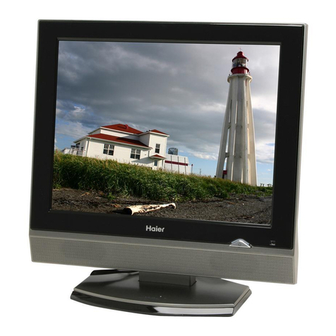
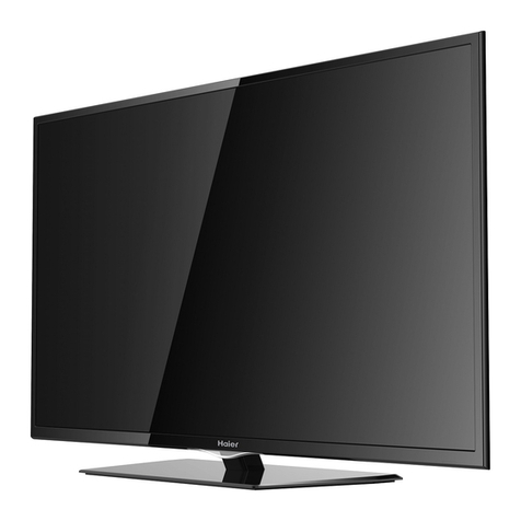
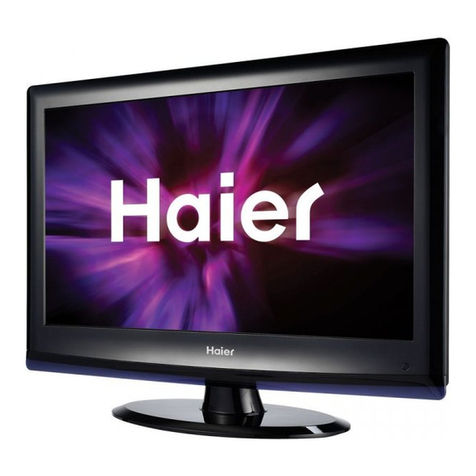
Haier L42H8 User manual

L42H8
(MST6E89)
Order NO.WH070625S001V0
@(2007)(Haier Electronic Company Limited)
All rights reserved. Unauthorized copying and distribution is a
violation of law.

2
WARNING
This service information is designed for experienced repair technicians only and is not designed for use
by the general public. It does not contain warnings or cautions to advise non-technical individuals of
potential dangers in attempting to service a product. Products powered by electricity should be serviced
or repaired only by experienced professional technicians. Any attempt to service or repair the product
deal with in this service information by anyone else could result in serious injury or death.
CONTENT
1. SPECIFICATIONS……………………………………………………………………………..3
2. WARNING……………………………………………………………………………………. .3
3. LOCATION OF CONTROLS AND COMPONENTS…………………………………….. . 5
3.1.Board Location……………………………….. ………………………………….……. 5
3.2 Main Board……………..……………………………….. ……………………………. .6
3.3 Side Av Board……………………………….. ………………………………………….7
3.4 Power Board…………………………….…………………….. ………………………. 7
3.5 LCD Panel……………………………….. ……………………………………………. .8
4. FEATURES AND TECHINICAL DESCRIPTION……………………………………….…10
5. INSTALLATION INSTRUCTIONS………………………………… ………………………12
5.1 External Equipment Connections………………………………….. ……… ………...13
6. OPERATION INSTRUCTIONS…………………………………………………………….17
6.1 Front Panel Controls……………………………….. ………………………………….17
6.2 Back Panel Controls……………………………….. ………….………………………17
6.3 Setting Up Your Remote Control ………………………….. …..…………………….18
7. DISASSEMBLY INSTRUCTIONS……………………………………..……………….….20
7.1 Whole Machine………………………………………………...……………….……….20
7.2 Connection Sketch Interpretat ………………………………..…….……………….21
8. MEASUREMENTS AND ADJUSTMENTS……………………………………………..…21
8.1 The Way to Factory Mode Menu…………… ……………...……………….………21
8.2 The default of Factory Mode Menu ………………………………..…….………….22
9. BLOCK DIAGRAM AND CIRCUIT DIAGRAM………………………………………..…..23
10. TROUBLE SHOOTING GUIDE…………………………………………………..…….….35
10.1. Simple check…………………………………………………………..…………….. 35
10.2. Main board failure check……………………………………………..……………. .35
10.3. Pannel failure ……………..………………………………………………………….37
11. MAINTENANCE……………………………………………………………….…………….38

3
1. Specification
Model L42H8
Screen size 42
Aspect ratio 16:9
Resolution 1366 x 768
Response Time(ms) 8ms
Angel of view H:178°/V:178°
Color display 16.7M
NO.of preset channels 200
OSD language English/Simple Chinese
Color system PAL
Audio system B/G
Audio output power(Built-in)(W) 7W X2
Audio output power(outer)(W) NO
Total power input(W)250
Voltage range(V)150-240
Power frequency(Hz)50/60
Time of sleep timer(MINS) 240
Net weight(KG) 24.9
Gross weight(KG) 31.6
Net dimension(MM) 1023*328*730
Packaged dimension(MM) 1115*375*830
2.Warning
WARNING
RISKELECTRIC SHOCK
DONOT OPEN
WARNING:To reduce the risk of electric shock don’t remove cover or back.
No user-serviceable parts inside refer service to qualified service personnel.
Safety of operators has been taken into consideration at the design and manufacture phase, but
inappropriate operation may cause electric shock or fire. To prevent the product from being damaged,
the following rules should be observed for the installation, use and maintenance of the product. Read
the following safety instruction before starting the operation.
The User Manual uses the following symbols to ensure a safe operation and prevent any damage to
operators or properties:

4
THIS SYMBOL INDICATES THAT HIGH VOLTAGE IS PRESENT INSIDE . IT IS
DANGEROUS TO MAKE ANY KING OF CONTACT WITH ANY INSIDE PART OF THIS
PRODUCT.
THIS SYMBOL INDICATES THAT THERE ARE IMPORTANT OPERATING AND
MAINTENANCE INSTRUCTIONS IN THE LITERATURE ACCOMPANYING THE
APPLIANCE.
IMPORTANT SAFETY INSTRUCTIONS
Read all of the instructions before using this appliance. When using this appliance, always
exercise basic safety precautions, including the following:
1) Save these Instructions ---the safety and operating instructions should be retained for future
reference.
2) All warning on the appliance and in the operating instructions should be followed.
3) Cleaning --- Unplug from the wall outlet before cleaning. Do not use liquid cleaners or aerosol
cleaners. Use only dry cloth for cleaning.
4) Attachments ---do not use attachments not recommended by the manufacturer as they may cause
hazards.
5) Water and moisture -- do not place this product near water, for example, near a bathtub, wash bowl,
kitchen sink, laundry tub, in a wet basement, or near a swimming pool.
6) Accessories ---do not place this unit on an unstable cart, stand, tripod, bracket, or table. Use only
with a cart, stand, tripod, bracket, or table recommend by the manufacture, or sold with the unit.
7) Ventilation ---Slots and openings in the cabinets and the back or bottom are provided for ventilation.
These openings must not be blocked. In a built in installation such a bookcase or rack do not install
product unless proper ventilation is provided.
8) Power Source ---this TV should be operated only from the type of power source indicated on the
rating label. If you are not sure of the type of power supply to your home, consult your appliance dealer
or local power company.
9) Do not defeat the safety purpose of the polarized or grounding-type plug. A polarized plug has two
blades with one wider than the other. A grounding type plug has two blades and a third grounding prong.
The wide blade or the third prong is provided for your safety. If the provided plug does not fit into your
outlet, consult an electrician for replacement of the obsolete outlet. To prevent electric shock, ensure
the grounding pin on the AC cord power plug is securely connected.
10) Power cord protection ---Power supply cords should be routed so that they are not likely to be
walked on or pinched by items placed upon or against them. Pay particular attention to cords or plugs,
convenience receptacle, and the point where they exit from the appliance.
11) Lighting precaution ---for added protection for this product during a lighting storm or when it is left
unattended for long period of time, unplug it from the wall outlet and disconnect the antenna or cable
system. This will prevent damage to the product due to lighting and power line surges.
12) Never push objects of any kind into this product through openings as they may touch dangerous
5
voltage point or short out parts that could result in a fire or electric shock. Avoid spilling liquid of any kind
on the product.
13) Servicing ---do not attempt to service the product by yourself, as opening or removing covers may
expose you to dangerous voltage or other hazards. Refer all servicing to authorized service personnel.
14) Unplug this unit from the wall outlet and refer servicing to qualified service personnel under the
following conditions:
a. When the power supply cord or plug is damaged or frayed.
b. If liquid has been spilled, or objects have been fallen into the unit.
c. If the unit has been exposed to rain or water.
d. If the unit does not operate normally by following the operating instructions. Adjust only those
controls that are covered by the operating instructions, as improper adjustment of other controls
may result in damage and will often require extensive work by a qualified technician to restore
the unit to its normal operation.
e. If the unit has been dropped or damaged in any way.
f. When the unit exhibits a distinct change in performance; this indicates a need for service.
15) Heat --- The product should be situated away heat source such as radiators, heat registers, stoves,
or other products (Including amplifiers) that product heat.
16) Overloading ---Do not overload wall outlets and extension cord as this can result in a risk of fire or
electric shock.
SAVE THESE INSTRUCTIONS
Thank you for using our Haier product. This easy-to-use manual will guide you in getting the best use of
your product. Remember to record the model and serial number. They are on label in back of the unit.
Staple your receipt to your manual. You will need it to obtain warranty service.
3. LOCATION OF CONTROLS AND COMPONENTS
3.1Board Location
No. Parts number Description
A Board 0090715292 Main Board
B Board 0094000731 Power Board
C Board 0094000589 LCD Panel
D Board 0090715311 Key Board
E Board 0090713250 Remote Board
3.2 Main Board

6
3.2.1 Function Description:
Process signal which incept from Tunner,then translate into signal which panel can display.
3.3Side AV Board(Fasened on the Rear Cover)

7
3.4Power Board
3.4.1 Function Description:
Supply power for Main board and Panel.
3.4.2 Connector definition
CN2:
PIN NUMBER Designation
1 24V
2 24V
3 24V
4 24V
5 24V
6 GND
7 GND
8 GND
9 GND
10 GND
CN4:
PIN NUMBER Designation
1 ON/OFF
2 GND

8
3 5VSB
4 GND
5 GND
6 12V
7 12V
CN6:
PIN NUMBER Designation
1 16.5V
2 16.5V
3 GND
4 GND
3.5 LCD PANNEL
3.5.1 Function Description:
Display the signal.
3.5.2 Connector defination
MODULE CONNECTOR (CN1) PIN CONFIGURATION
LCD Connector (CN1): FI-X30SSL-HF (Manufactured by JAE) or Equivalent
Mating Connector: FI-30C2L (Manufactured by JAE) or Equivalent

9
Note:
1. The pin no 9 is an option pin for DISM or LG format. (LG Format=”GND” or “OPEN”/DISM
Format=”VCC”)
2. The pin no 10 is an option pin for DCR Function (Enable=”VCC”/Disable=”GND”)
3. The pin no 30 is LCD Test option.
“AGP” (Auto Generation LCM operates Pattern) or “NSB”( No Signal Black) is case that LVDS
signals are out of frequency or abnormal condition in spite of 12 volt power supply.
LPL recommends “NSB”. (AGP: “VCC” or “OPEN”/NSB:”GND”)
4. All GND Pin should be connected together, which should be also connected to the LCD
module’s metal frame.
5. All Vlcd (power input) pins should be connected together.
6. Input Levels of LVDS signals are based on the IEA 664 Standard.
INVERTOR CONNECTOR PIN CONFIGULATION

10
4.FEATURES AND TECHINICAL DESCRIPTION
1 TFT/CRT LC420WX7
2 Display area 42 inches
3 Aspect ratio 16:9
4 Resolution 1366*768
5 Brightness 500cd/m2
6 Contrast(Darkroom) 1500:1
7 Response time(ms) 8ms
8 Analog Color system PAL
9 digital Color system NO
10 Audio system B/G
11 Angel of view 178
12 NO.of preset channels 200
13 Picture mode Yes
14 Color display 16.7 M
15 OSD languages English/Simple Chinese
16 MEMC NO
17
Picture
ColorMangement NO
18 Bass Yes

11
19 Treble Yes
20 Digital Bass Yes
21 Super woofer No
22 Treble/bass boost Yes
23 AV stereo Yes
24 Surrounding sound Yes
25 BTSC No
26 Automatic Volume Control(AVC) Yes
27 Auto-volume leveling Yes
28 Equalizer Yes
29 Mute Yes
30 MTS No
31 Multi-audio modes Yes
32
SOUND
Multi-sound mode Yes
33 Side AV input Yes
34 Rear AV input Yes
35 AV output Yes
36 DVD terminal Yes
37 S-video jack Yes
38 YCbCr Yes
39 Y PB PR Yes
40 D-SUB jack Yes
41 DVI socket No
42 SCART jack No
43 RS-232 jack No
44 USB jack No
45 HDMI Yes
46
Jack
Phone Yes
47 Semitransparent menu Yes
48 SCAN Yes
49 16:9 mode Yes
50 PIP No
51 V-CHIP No
52 CCD No
53 Color temperature Yes
54 PC Automatic Adjust Yes
55 Scaler Mode No
56 Non-flashing channel changing No
57 Calendar No
58 Auto-timer on NO
59
Software
TELETEXT Yes
60 NO. of built-in speakers 2
61 NO. of outer speakers No
62 Audio output power(Built-in)(W) 7W X2
63 Audio output power(outer)(W) No
64
Total power input(W)250W

12
65 Voltage range(V)150-240V
66 Power frequency(Hz)50/60Hz
67 Time of sleep timer(MINS) 240
68 Net weight kg 24.9
69 Net weight(Including Base) kg 31.6
70 Gross weight kg 31.6
71 Gross weight(Including Base) kg 31.6
72 Net dimension(mm) 1023*328*730
73 Net dimension (Including Base) mm 1023*328*730
74 Packaged dimension mm 1115*375*830
75 Packaged dimension(Including Base) mm 1115*375*830
76 Base /
77 Great Solid ZPB-BG05
78 Quantity for 20FT 60
79 Quantity for 40FT 124
80
Electricity
parameter
Quantity for 40HC 186
5. INSTALLATION INSTRUCTIONS
(Note: This information is provided to help guide your installation. Hiaer assumes no liability for errors
or the outcome of any installation since each project is unique and tools, materials, techniques, local
codes and regulations vary and change.)Preparing for Your Installation In planning your flat-panel
television install, there are some questions you'll need to ask yourself first. Once these are answered,
you're ready to begin your project: Seating area
Is the system designed around a "sweet spot" or for the same sound and picture everywhere? There
are different products for different designs.
Furniture
You will need room for your equipment —most home theater components require a space
18-20 inches wide by 22-24 inches deep to fit properly.
What kind of seating do you want? Is the room primarily a home theater entertainment area, or
will music be part of what it's used for as well?
Aesthetics
Make sure the equipment you choose doesn't overwhelm the room. Do you have room for a
projection screen, or will you need to find something a little more space effective?
Wire access
Have you planned how you will run wires to your speaker locations? Will you have all of your
equipment next to the TV, or will it be hidden in another room or area?
Do you have enough wire to complete the project? Too much wire is better than not enough.
Mounting
Does your TV require a proprietary mounting device? Some manufacturers require specific
mounts for their TVs.

13
What is the size and weight of your TV? All brackets have weight and size restrictions. It is
necessary to make sure your TV will fit within the limitations of the mount.
Are you going to fit the mount into a tight space or cabinetry? It may be impossible to use some
brackets if the space does not allow the proper leverage.
Will you need to tilt or move the TV from time to time? There are mounts available that will
adjust to the seating arrangement in the room.
Will the TV be positioned at an angle? Special mounts and techniques may be required to keep
your TV mounted at or into an angle.
What will the TV be mounted to? It is necessary to have proper support for your TV. In most cases,
there will be wood, metal or mortar to mount the bracket to.
5.1 External Equipment Connections
Accessories
5.1.1 Antenna Connections
--Antenna or Cable Service without a Cable Box Connections
--For optimum picture quality, adjust antenna direction if needed.

14
5.1.2 VCR Connections
--To avoid picture noise (interference),leave an adequate distance between the VCR and TV.

15
5.1.3 HDMI Connections
5.1.4 DVD Connections

16
5.1.5 PC Connections

17
6. OPERATION INSTRUCTIONS
Basal information
6.1 Front panel controls
6.2 Back panel controls

18
6.3 Setting Up Your Remote Control

19

20
7. DISASSEMBLY INSTRUCTIONS
7.1.whole machine
This manual suits for next models
1
Table of contents
Other Haier TV manuals

Haier
Haier MX-TM7414Mpeg4 User manual

Haier
Haier LE32B9000 User manual

Haier
Haier HTX21S31 User manual

Haier
Haier HLC22RW1 User manual

Haier
Haier 29FV6 User manual

Haier
Haier 29FV6H User manual

Haier
Haier CV1311B User manual

Haier
Haier HL32XSL2a User manual

Haier
Haier 29FA10 User manual

Haier
Haier LT22R3CWW2 User manual

Haier
Haier DTA-1518 User manual

Haier
Haier 29FV6H User manual

Haier
Haier HL40BG - 40" LCD TV User manual

Haier
Haier 25F9K-T User manual

Haier
Haier HL26ATB User manual

Haier
Haier HL42XP22 User manual

Haier
Haier HTAF29S User manual

Haier
Haier 28e2000 User manual

Haier
Haier HL22R3 User manual

Haier
Haier HTN13R12 User manual