Haier MX-TM7414Mpeg4 User manual

SERVICEMANUAL
ColourTelevision
Haiermodel:
DTA-1496
Customermodel:
MX-TM7414Mpeg4
l FEATURES
l DVD-TV14 COMBO
l AUTO TUNE/218 CHANNES
l DVD/VCD/SVCD/CD/CD-R/CD-RW/JPEG/MP3COMPATIBLE
l FORMATO DEVIDEO 4:3PS 4:3LB
l DOLBYAC-3DECODE
l PANATALLOCK
CAUTION READ
THISMANUALCAREFULLYTODIAGNOSE
TROUBLECORRECTLYBEFOREOFFERING
SERVICE.

.
2
CONTENTS
1.Safetyprecautions……………………………………………………………..……………3
2.TVblock diagram……………………………………………………………………..…….4
3.ReplacementofmemoryIC………………………………………………………….……5
4.Service adjustment……………………………………………………………..…………...5
5.ICsfunctionaldescription…………………………………………………………………8
6.Testpointwaveform………………………………………………………………………10
7.All ICsvoltages……………………………..……………………………………………….10
8.Purity/convergence adjustment………………………………………………………11
9.DVDmaintenance…………………………………………………………………………13

.
3
1. SAFETY PRECAUTIONS
1.Thedesignofthisproductcontainsspecial hardware,many
circuitsandcomponentsespeciallyforsafetypurposes.For
continued protection,nochangesshouldbemadetothe
originaldesignunless authorizedinwritingbythe
manufacturer.Replacementpartsmustbeidenticaltothose
usedintheoriginal circuits.Serviceshouldbeperformed by
qualifiedpersonnelonly.
2.Alterationsofthedesignorcircuitryoftheproductsshould
notbemade.Anydesignalterationsoradditionswill voidthe
manufacturer swarrantyandwill furtherrelievethe
manufacturerofresponsibilityforpersonal injuryorproperty
damageresulting therefrom.
3.Manyelectrical andmechanical partsintheproductshave
special safety-related characteristics.Thesecharacteristics
areoften notevidentfromvisual inspectionnorcan the
protectionaffordedbythemnecessarilybeobtained byusing
replacementcomponentsrated forhighervoltage,wattage,
etc.Replacementpartswhichhavethesespecialsafety
characteristics areidentifiedinthepartslistofService
manual.Electrical componentshavingsuchfeaturesare
identifiedbyshadingon theschematics andby( )on
thepartslistinServicemanual.Theuseofasubstitute
replacementwhichdoesnothavethesamesafety
characteristics astherecommendedreplacementpart
showninthepartslistofServicemanual maycauseshock,
fire, orotherhazards
4. Don’tshortbetweentheLIVE sideground and
ISOLATED(NEUTRAL)sidegroundorEARTHside
groundwhenrepairing.Somemodel spowercircuitis
partlydifferentintheGND.ThedifferenceoftheGNDis
shownbytheLIVE:()sideGND,ISOLATED
(NEUTRAL): ()sideGNDandEARTH: ()sideGND.
Don tshortbetweentheLIVEsideGNDandISOLATED
(NEUTRAL)sideGND orEARTHsideGND andnever
measurewithameasuringapparatus(oscilloscopeetc.)the
LIVEsideGND andISOLATED(NEUTRAL)sideGNDor
EARTHsideGND atthesametime.If abovenotewillnotbe
kept, afuseoranypartswill bebroken.
5.Ifanyrepairhasbeenmadetothechassis,itis
recommended thattheB1settingshouldbecheckedor
adjusted(See ADJUSTMENT OF B1POWERSUPPLY).
6.The highvoltageapplied tothepicturetubemustconformto
that specifiedinServicemanual. Excessivehighvoltagecan
causean increasein X-Rayemission,arcingand possible
componentdamage,thereforeoperationunderexcessive
highvoltageconditionsshouldbekepttoaminimum,or
shouldbeprevented.Ifseverearcingoccurs,removetheAC
powerimmediatelyanddeterminethecausebyvisual
inspection (incorrectinstallation,cracked ormelted high
voltageharness,poorsoldering,etc.).Tomaintain theproper
minimumlevel ofsoftX-Rayemission,componentsin the
highvoltagecircuitryincluding thepicturetubemustbethe
exactreplacementsoralternativesapproved bythe
manufacturerofthecompleteproduct.
7.Donotcheckhighvoltagebydrawinganarc.Useahigh
voltagemeterorahighvoltageprobewithaVTVM.
Dischargethepicturetubebeforeattemptingmeter
connection,byconnectingacliplead tothegroundframe
andconnectingtheotherendofthelead through a10kΩ2W
resistortotheanodebutton.
8.Whenserviceisrequired,observetheoriginal leaddress.
Extraprecautionshould begiventoassurecorrectlead
dress in thehighvoltagecircuitarea.Whereashortcircuit
hasoccurred,thosecomponentsthatindicateevidenceof
overheatingshouldbereplaced.Alwaysusethe
manufacturer sreplacement components.
9.IsolationCheck
(SafetyforElectricalShockHazard)
Afterre-assemblingtheproduct, alwaysperformanisolation
checkon theexposed metal partsofthecabinet(antenna
terminals,video/audioinputandoutputterminals,Control
knobs,metal cabinet, screwheads,earphonejack,control
shafts,etc.)tobesuretheproductissafetooperatewithout
dangerofelectricalshock.
10.The surfaceoftheTVscreeniscoatedwithathinfilmwhich
can easilybedamaged. Beverycarefulwithitwhen handle
theTV. ShouldtheTVscreen becomesoiled, wipeitwitha
softdrycloth.Neverrubitforcefully.Neveruseanycleaner
ordetergent onit.
(1)DielectricStrengthTest
Theisolation between theACprimarycircuitandallmetal
partsexposed totheuser,particularlyanyexposed metal
parthavingareturnpathtothechassisshouldwithstanda
voltageof3000VAC(r.m.s.)foraperiodofonesecond.
(…Withstandavoltageof 1100VAC(r.m.s.)toanappliance
ratedupto120V,and 3000VAC(r.m.s.)toanappliance
rated200Vormore, foraperiodofonesecond.)
Thismethodoftestrequirestestequipmentnotgenerally
found in theservicetrade.
(2)LeakageCurrent Check
PlugtheAClinecorddirectlyintotheACoutlet(donotuse
lineisolation transformersduring thischeck).Using a
“LeakageCurrent Tester”,measuretheleakagecurrentfrom
eachexposedmetal partofthecabinet, particularlyany
exposedmetal parthavingareturnpathtothechassis,toa
knowngood earthground(waterpipe,etc.).Anyleakage
current must not exceed0.5mAAC(r.m.s.).
However,intropical area,thismustnotexceed0.2mAAC
(r.m.s.).
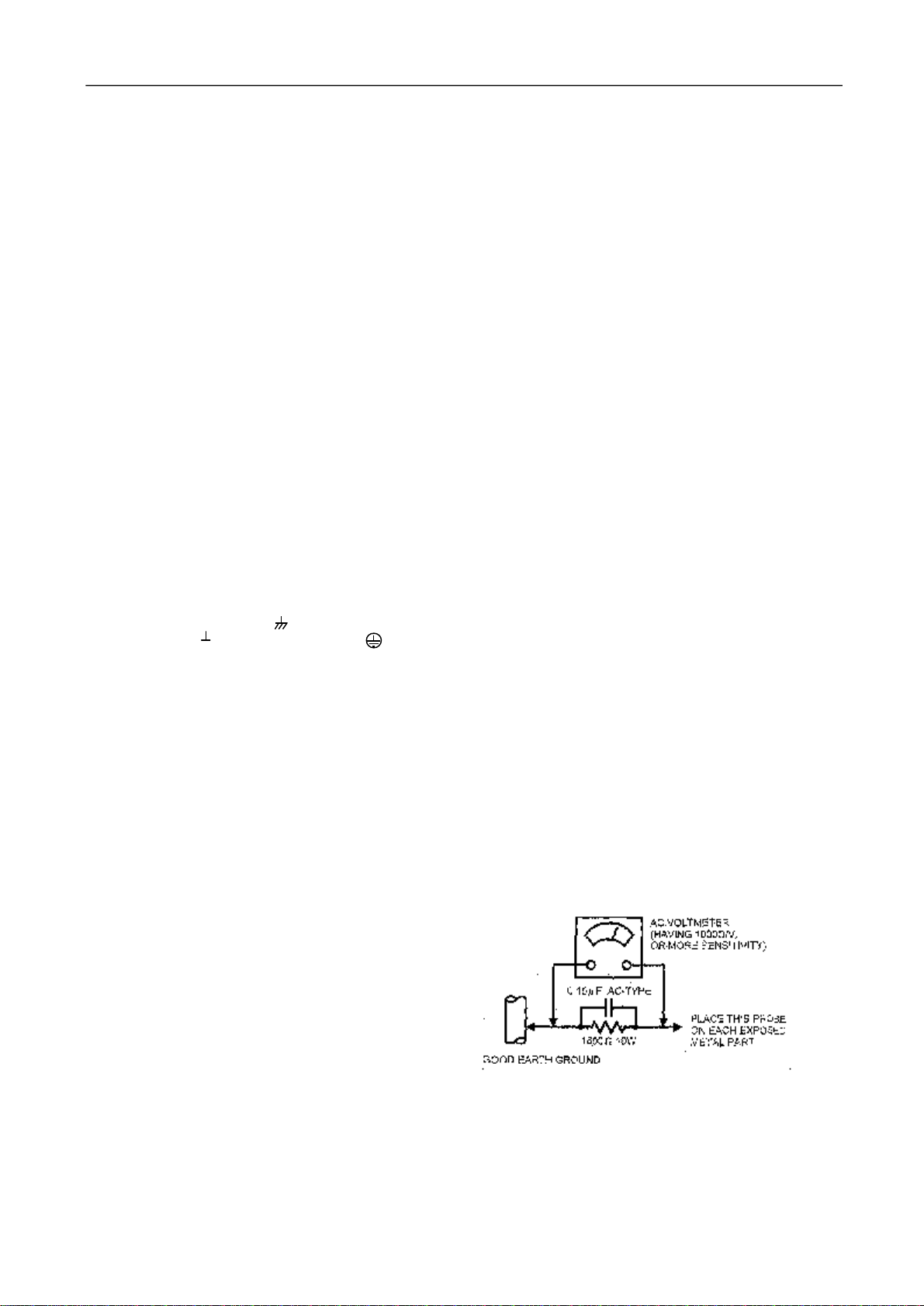
●AlternateCheckMethod
PlugtheAClinecorddirectlyintotheACoutlet (donotuse
alineisolationtransformerduringthischeck.).UseanAC
voltmeterhaving 1000 ohmspervoltormoresensitivityin
thefollowingmanner.Connecta1500Ω10Wresistor
paralleled bya0.15μFAC-typecapacitorbetween an
exposed metal partand aknowngoodearthground(water
pipe,etc.).MeasuretheACvoltageacross theresistorwith
theACvoltmeter.Movetheresistorconnection toeach
exposed metal part, particularlyanyexposed metal part
having areturnpathtothechassis,and measuretheAC
voltageacross theresistor.Now,reversetheplug intheAC
outletand repeateachmeasurement.Anyvoltagemeasured
mustnotexceed0.75VAC(r.m.s.).Thiscorrespondsto
0.5mAAC(r.m.s.).
However,intropical area,thismustnotexceed0.3VAC
(r.m.s.).
Thiscorrespondsto0.2mAAC(r.m.s.)

5
3. REPLACEMENTOFMEMORYIC
1.MEMORYIC.
ThisTVusesmemory IC.Inthe memoryICarememorized dataforcorrectlyoperating the video and deflection
circuits.
2.PROCEDUREFORREPLACING MEMORYIC
(1)Poweroff
Switchthe poweroffand unplug the powercordfromACoutlet.
(2)ReplaceIC
Besuretousememory ICwritten withthe initialdatavalues.
(3)PowerOn
Plug the powercordintothe ACoutlet and switchthe poweron.
(4)Check and set SYSTEM default value:
1)Press “MUTE”à“CALL”à“-\--“à“CALL”à“MUTE”buttonsinsequencetoenterintofactory
status.
2)Ifthe memoryIChaven t been written withthe initial data, press [Program+]/[Program-]toselectitem
INITand press [VOLUME+] / [VOLUME-] tostart initializememory IC.
3)Check the setting value ofthe SYSTEMdefaultvalue ofTablebelow.Ifthe value isdifferent, select
itemsby[Program+] / [Program-] keysand set value by[VOLUME+] / [VOLUME-] keys.
4)Press “EXIT”button toreturntothe normalscreen.
4. SERVICEADJUSTMENT
Specificoperation: useremotecontroller
Press “MUTE”à“CALL”à“-\--“à“CALL”à“MUTE”buttonsinsequencetoenterintofactory mode.
Press [Program+]/[Program-]toselectitemsand press [VOLUME+]/[VOLUME-] key,tomakedataadjustment
ofcorresponding factory menus.
Press “EXIT”keytoexit factory mode.
Focusadjustment
1.Receiveacrosshatchsignal.
2.Whilewatching the screen,adjustthe FOCUSVRon the FBTtomakethe verticaland horizontallinesas
fine and sharpaspossible.
Geometrical adjustment
ReceivePALstandardcompletepatternsignal.
Adjustment steps:
a)Adjust VSL, tothe centrehorizontalline just appearsfromhalfbottomshadow.
b)Adjust VAM, toget 92% ofverticalpicturecontentswouldbe displayed on CRT.
c) Adjust VSH, the centrehorizontalline correspondstoCRTverticalcentre.
d)Adjust SCL, tothe linearityofPcardfieldisinpropercondition.
e)Adjust HSH, toget the picturehorizontalcentrecorrespond toCRThorizontalcentre.
ReceiveNTSCsignaland repeat aboveadjustment.
AGCAdjustment
Receive60dBμ(1mV) VHcolourbarpatternsignal.
SelectTOPitem.
Adjust value, tonoisereducegraduallyand just disappeared point.
CRTcutoff andwhitebalance adjustment
a)CRTcut offadjustment
1.Select itemVG2B, then adjust value to32.
2.PRESS “0”key,when the screen shows”VG2”adjustthe SCREENcontrolon Flyback transformerto
makethe screen showalternating flashing charactersof “INSIDEHIGHINSIDELOW”.
b)Whitebalanceadjustment
1.ReceiveaBlack and Whitepattern.
2.Adjust WRP, WRG, WRBitemstoget colourtemperature9300K ±3JND.

6
AdjustableItems
Direct access keyItems Description Preset Remark
“1”5/6HSH Horizontalshift ON A
“2”5/6VSL Verticalslop 32 A
5/6VAM Verticalamplitude 23 A
5/6SCL S-correction 17 A
5/6VSH Verticalshift 27 A
5/6VOF OSDVerticaloffset 37 A
HOF* OSDHorizontaloffset 42 A
“3”RED Black leveloffset R 32 A
GRN Black leveloffset G 32 A
WPR Whitepoint R 30 A
WPG Whitepoint G 26 A
WPB Whitepoint B 38 A
“4”TOP AGCTake-overpoint 20 A
VOL Volume 42
9860 Sub-volumeofTDA9860/59 18
HDOL Cathodedrivelevel 59
AGC IFAGCspeed 1
VG2B VG2Brightness 42
IFFS 2
“5”Picturepreset 1
0CON Listen: Contrast 0 A
0BRI Listen: Brightness 0 A
0COL Listen: Colour 50 A
0SHP Listen: Sharpness 50 A
1CON Soft: Contrast 45 A
1BRI Soft: Brightness 45 A
1COL Soft: Colour 50 A
1SHP Soft: Sharpness 50 A
“6”Picturepreset 2
2CON Standard: Contrast 75 A
2BRI Standard: Brightness 50 A
2COL Standard: Colour 50 A
2SHP Standard: Sharpness 60 A
3CON Dynamic: Contrast 85 A
3BRI Dynamic: Brightness 60 A
3COL Dynamic: Colour 60 A
3SHP Dynamic: Sharpness 80 A
NOTE:THEITEMSWITHREMARK “A”ISADJUSTABLEDATA.
Optional data
1.OP1
Bit Function Description Preset Remark
Bit 0 VG2_MODE 1= 0 EA
Bit 1 YPRPB 1=Enable 1 EA
Bit 2 SUPERWOOFER TranslucenceOSDmanual1=Enable 0 EA
Bit 3 WOOFER_VOL
1=Enable(CanonlybeselectedeitherRGBandDVD)
0 EA
Bit 4 AV2 1=Enable 1 EA
Bit 5 SVHS 1=Enable 0 EA
Bit 6 DVD 1=Enable 0 EA
Bit 7 RGB 1=Enable 1 EA

7
2.OP2
Bit Function Description Preset Remark
Bit 7 FSL 1=21dBμV0=26dBμV 0 EA
Bit 6 SOY 1=Enable 1 EA
Bit 5 ARABIC_SET 1=Enable 0 EA
Bit 4 FARSI_SET 1=Enable0 EA
Bit 3 CYRILLIC_SET 0 EA
Bit 2 EUROUP_SET 1=Enable 1 EA
Bit 1 AUTO_SOUND 1 EA
Bit 0 AVL 1=Enable 1 EA
3.OP3
Bit Function Description Preset Remark
Bit 7 RUSSIA 1=Enable 0 EA
Bit 6 ITALY 1=Enable 0 EA
Bit 5 GERMANY 1=Enable 0 EA
Bit 4 FRANCE 1=Enable 0 EA
Bit 3 RUTKISH 1=Enable 0 EA
Bit 2 ARABIC 1=Enable 0 EA
Bit 1 FARSI 1=Enable 0 EA
Bit 0 ENGLISH 1=Enable 1 EA
4.OP4
Bit Function Description Preset Remark
Bit 6 HALFTONE 1=Enable 1 EA
Bit 5 IDENT_SENSITIVE 1 EA
Bit 4 HCO 1=Enable 0 EA
Bit 3 LOGO 1 EA
Bit 2 TILT 0 EA
Bit 1 SPANISH 1 EA
Bit 0 ROMANIA 0 EA
5.OP5
Bit Function Description Preset Remark
Bit 7 STORE_AV 1= Enable 1 EA
Bit 6 OSO 1= Enable 0 EA
Bit 5 SOFR_CHANGE 1=Enable 0 EA
Bit 4 FADE 1=Enable 0 EA
Bit 3 SOUND_M 1= Enable 0 EA
Bit 2 SOUND_I 1= Enable 0 EA
Bit 1 SOUND_BG 1=EnableWithDVDselect 1 1 EA
Bit 0 SOUND_DK 1=Enable 0 EA
6.OP6
Bit Function Description Preset Remark
Bit 7 RESERVE 1=Enable 0 EA
Bit 6 POR_WHEN_BLUE 1=Enable 1 EA
Bit 5 MENU_MIDLINE 1=Enable 1 EA
Bit 4 MENU_BLUE 1=Enable 1 EA
Bit 3 CHILDLOCK 1=Enable 1 EA
Bit 2 16_9 1=Enable 0 EA
Bit 1 BLUE_SCREEN 1=Enable 1 EA
Bit 0 LOGO_LISTEN 1 EA

8
7.OP7
Bit Function Description Preset Remark
Bit 7 FMWS 1=Enable 1 EA
Bit 6 HOTEL 1=Enable 0 EA
Bit 5 PROG_ID 1=Enable 0 EA
Bit 4 LED 1=Enable 0 EA
Bit 3 TWIST 1=Enable 0 EA
Bit 2 BYELORUSSIAN 1=Enable 0 EA
Bit 1 UKRANIAN 1=Enable 0 EA
Bit 0 AV1 1=Enable 1 EA
8.OP8
Bit Function Description Preset Remark
Bit 6 DIRECT_SWITCH_ON
1=Enable 0 EA
Bit 5 INNER_DVD 1=Enable 1 EA
Bit 4 PROG_FREQ 1=Enable 0 EA
Bit 3 FAST_BAR 1=Enable 1 EA
Bit 2 AUSTRALIA 1=Enable 0 EA
Bit 1 FREQ 1=Enable 1 EA
Bit 0 9860 1=Enable 0 EA
Note:Don t adjust anyOPTIONitems, pleaseinformthe engineerabout anychange.
5. ICsfunctional description
1.N501 UOCOM9351
SYMBOL PIN DESCRIPTION
STAND BYoutput. 1 InSTAND BYmode, lowlevel(PowerOFF).
ForPowerONthispinwill behigh.
SCL 2 I2C-busclock line
SDA 3 I2C-busdataline
TUNING 4 tuning Voltage(Vt)PWMoutput
KEY 5 Controlkeys input
SYSTEM 6 TVsystemcontrol
VOL 7 Sound VolumecontrolPWMoutput
MUTE 8 Sound muteoutput
VSSC/P 9 Digit ground for μ-controllercoreand periphery
CTL 10 DVDpowercontrol
STANDBY 11 STANDBYcontrol
VSSA 12 Analog ground of digitalground ofTV-processor
SECPLL 13 Internallyconnected
VP2 14 2nd supplyvoltageTV-processor(+8V)
DECDIG 15 decoupling digitalsupplyofTV-processor
PH2LF 16 Phase-2filter
PH1LF 17 Phase-1filter
GND3 18 Ground 3forTV-processor
DECBG 19 Band gap decoupling
AVL/EWD 20 Automaticvolumelevelling
VDRB 21 VerticaldriveBoutput
VDRA 22 VerticaldriveAoutput
IFIN1 23 IFinput 1
IFIN2 24 IFinput 2

9
IREF 25 Referencecurrent input
VSC 26 Verticalsawtoothcapacitor
TUNERAGC 27 TunerAGCoutput
AUDEEM/SIFIN1*1 28 AudiodeemphasizeorSIFinput
DECSDEM/SIFIN229 Decoupling sound demodulator
GND2 30 Ground 2forTVprocessor
SNDPLL/SIFAGC*1 31 Narrowband PLLfilter
AVL 32 AutomaticVolumeLevelling
HOUT 33 Horizontaloutput
FBISO 34 Flyback input/sandcastleoutput
AUDEXT 35 Externalaudiooutput
EHTO 36 EHT/overvoltageprotection input
PLLIF 37 IF-PLLloop filter
IFVO/SVO 38 IFvideooutput / selectedCVBS output
VP1 39 supplyvoltageTVprocessor
CVBS INT 40 internalCVBS input
GND1 41 ground forTVprocessor
CVBS/Y 42 CVBS/SVHS(Y)input
CHROMA 43 SVHS(C)input
AUDOUT 44 Audiooutput
INSSW2 45 YUVinsertion input
R2/VIN 46 Rinput / V(R-Y)input / PRinput
G2/YIN 47 G input / Yinput
B2/UIN 48 Binput / U(B-Y)input / PB input
BCLIN 49 Beamcurrent limiterinput
BLKIN 50 Black current input
RO 51 Redoutput
GO 52 Greenoutput
BO 53 Blueoutput
VDDA 54 Analog supplyof ClosedCaption decoderand digitalsupplyofTV-processor(3.3V)
VPE 55 Ground
VDDC 56 Digitalsupplytocore(3.3V)
OSCGND 57 Oscillatorground supply
XTALIN 58 Crystaloscillatorinput
XTALOUT 59 Crystaloscillatoroutput
RESET 60 Ground
VDDP 61 Digitalsupplytoperiphery(+3.3V)
P1.0/INT1 62 AV1/ AV2modeOutput.
P1.1/T0 63 AV/S-VHSmodeOutput.
P1.2/INT0 64 Remotecontrolsignalinput.
Note Pin TV SVHS AV1 AV2
62 1 0 0 1
63 1 1 0 0
2.N202 24C08/PCF8598
PIN Function
1 GND
2 GND
3 Upperresistance
4 GND
5 SDAdatawire
6 SCLclock wire
7 GND
8 +5VPower
3.N601: Sound poweramplify(AN7522N)
Symbol PINFunction Symbol PIN
Function
Vcc 1 Powersupply GND 7 ground
Out 1(+) 2 Ch1output (+) In2 8 Ch2input
GND(out 1) 3 Ch1Ground VOL 9 VolumeControl
Out 1(-) 4 Ch1output (-) Out 2(-) 10 Ch2output (-)
Standby 5 Muteinput GND(out 2) 11 Ch2Ground

10
In1 6 Ch1input Out 2(+) 12 Ch2output (+)
4.N301: Verticaloutput (TDA8357A)
Symbol PIN
Function Symbol PIN
Function
INVIN 1 Input PUMPUP 6 Pumpup power
INVIN 2 Input VOUT 7 Verticaloutput
Vcc 3 Pumpup power VPRO 8 Verticalprotection
VOUT 4 Verticaloutput VFEEDBACK 9 Verticalfeedback
GND 5 Ground
5.U101:Tuner
PIN
Function PIN
Function
1 AGC 7 +5V
2 vacant 8 vacant
3 Gnd 9 Vt 33V
4 SCL 10 Gnd
5 SDA 11IFOut
6 +5V
6. Test pointWaveforms
7. ICvoltages
5Vpp
0.9Vpp
1.3Vpp
H
H
1Vpp
V
CRTKB
CRTKGCRTKR
95Vpp
95Vpp
95Vpp
H
H
H
TDA
9351
PIN53
2.5Vpp
2.5Vpp
3.8Vpp
H
H
H
TDA
9351
PIN52
TDA
9351
PIN51
TDA9
351
PIN
33
TDA9
351
PIN
34
0.8Vpp
V
TDA9351 PIN21 TDA9351 PIN22 TDA9351 PIN59
1.2Vpp
2.6Vpp
H
H
TDA9351 PIN40
TDA9351 PIN38

11
TDA9351
PIN
1 2 3 4 5 6 7 8 9 10
11
12
13
14
15
16
V 03.8
3.6
3.3
3.5
4.4
5.1
1.8
00.18
0.17
02.3
8 5 3
PIN
17
18
19
20
21
22
23
24
25
26
27
28
29
30
31
32
V 4 0 4 0.5
0.7
0.8
1.9
1.9
3.9
3.8
1.6
3.2
2.3
02.3
0.2
PIN
33
34
35
36
37
38
39
40
41
42
43
44
45
46
47
48
V 0.5
0.3
01.7
2.4
3.4
83.9
03.3
03.6
1.4
2.5
2.5
2.5
PIN
49
50
51
52
53
54
55
56
57
58
59
60
61
62
63
64
V 1.9
5.0
2.4
2.4
2.4
3.1
03.2
01.8
1.7
03.2
5.1
3.3
5
TDA8357
PIN
1 2 3 4 5 6 7 8 9
V 0.8
0.7
16 6.9
0 43 7.2 0.3 7.2
AN7522N
PIN
1 2 3 4 5 6 7 8 9 10 11 12
V 10 4.4 0 4.42.75
1.4 0 1.40.35
4.4 0 4.4
24C08/PCF8598
PIN
1 2 3 4 5 6 7 8
V 0 0 5.1
03.2
0 0 5.1
8. PURITY/ CONVERGENCEADJUSTMENT

12
PURITYADJUSTMENT
1.DemagnetizeCRT withthe demagnetizer.
2.Loosen the retainerscrewofthe deflection yoke.
3.Removethe wedges.
4.Inputagreen rastersignalfromthe signalgenerator,
and turnthe screen togreen raster.
5.Movethe deflection yokebackward.
6.Bring the long lug ofthe puritymagnetson the short
lug and position themhorizontally. (Fig2)
7.Adjustthe gap betweentwolugssothatthe GREEN
RASTERwillcomeintothe centreofthe screen.
(Fig. 3)
8.Movethedeflection yokeforward,andfixtheposition
ofthedeflection yokesothatthe wholescreen will
becomegreen.
9.Insert the wedge tothe top side of the deflection yoke
sothat it will not move.
10.Input acrosshatchsignal.
11.Verifythat the screen ishorizontal.
12. Inputred and blue rastersignals,and makesurethat
purityisproperlyadjusted.
CRT
WEDGE
DEFLECTION YOKE
P
46
P:PURITYMAGNET
4:4-POLES (convergence magnets)
6:6-POLES (convergence magnets)
P/CMAGNETS
Fig. 1
PURITYMAGNETS
Longlug
Short lug
Bring thelonglugovertheshortlug
and
position them horizontally.
Fig. 2
(FRONTVIEW)
GREENRASTER
CENTER
Fig. 3

13
STATICCONVERGENCEADJUSTMENT
1.Input acrosshatchsignal.
2.Using 4-poleconvergencemagnetsoverlapthered
and blue linesinthe centerofthe screen (Fig.1)and
turnthemtomagenta(red/blue).
3.Using 6-poleconvergencemagnetsoverlap the
magenta(red/blue)and green linesinthe centerofthe
screen and turnthemtowhite.
4.Repeat2and 3above,and makethe best
convergence.
DYNAMICCONVERGENCEADJUSTMENT
1.Movethedeflectionyokeupand downand overlap
linesinthe periphery. (Fig. 2)
2.Movethe deflectionyokelefttorightand overlap the
linesinthe periphery. (Fig. 3)
3.Repeat1and 2above,and makethe best
convergence.
Afteradjustment, fixthe wedge at the originalposition.
Fasten the retainerscrewofthe deflection yoke.
Fixthe 6magnetswithglue.
(FRONTVIEW)
Fig. 1
(FRONTVIEW)
REDGREENBLUE
BLUE
RED
GREENGREEN
REDBLUE
BLUEGREENRED
Fig.2
(FRONTVIEW)
REDGREENBLUEBLUEGREENRED
RED
GREEN
BLUE
BLUE
GREEN
RED
Fig. 3

14
9. DVDPart:Introduction ofMTK1389Dmaintenance
NOTE:MTK1389D isatype ofLSICforDVDdecode .MTK1389D ICconsistsof
RF,SERVO,DSP,DECODE,VIDEO DACand AUDIO DAC.
1.Undernormalpowersupplyconditions,the maintenanceplan forMT1389D mono-chipis:firstthe reset
circuitresetsthe MT1389D,afterthecrystaloscillatorcircuitgavethe clocksignal toMT1389D,MT1389D will
start the initialization check forFlash、E2PROM、SDRAM, aftereverything ischecked tobe normal,it willstart
initialization check forbuilt-inAudioDAC, servoand motorDriverIC.
2. Iftheall thea.m.partsaregood,thenMT1389Dwill send signaltomotorDrivertodrivetheservo
system,pickup then togenerateDVDlightforcollection,tracing the mainshafttocheckifthereisanydisc,and
confirmifitisCD format orDVDformat disc. If the discisinDVDformat, the systemwillread the datafromthe
discdirectly;ifitisinCD format built-inservowilldrivethe CD lasertosend out CD light and read the data, the
datathen will be amplified through built-inRFamplifierand senttoMT1389D decode partfordataprocessing,
released byMPEGand resolved intovideo dataand audiodata,then theywill be returned toanalog signals
through built-inVIDEO DAC、AUDIO DAC.
Decodersection
3.Thereispowersupply, clock and reset, but the systemdoesnot work.
1)Check ifallthe address wiresrequired forFLASHareexist,and iftheyareinnormalstatus,
especiallycheck ifthe A0~A15 ofFLASHhavenormalsignals,iftherearen t, then inspectMT1389D tosee if
thereisfaultysoldering.IftherearenormalsignalsatA0~A15,check ifthe address datasignalofMT1389D
and SDRAM isnormal. Ifit isnormal,then check the signalatA16~A19 ofMT1389D; iftherearealsosignals,
then checkthevideo outputwiresand AVfiltercircuit; ifthereisno signal,then check the corresponding pins
ofMT1389D tosee ifthereisanyshort circuit, breakorfaultysoldering.
4.Systeminnormaloperation, but the audiohasno sound.
1)Becausethe AUDIO DACisbuilt inMTK1389D IC.youneed tocheckthelowerpassing amplifying
circuitand the MUTEcircuitatthe back of the LPFcircuit. Alsocheck ifthereisanypowersupplytothe LPF
circuit.
2)Check ifthe powersupplyvoltage required forplaying isat normallevel.
ServoSection
5.Afterthe LOGO ofthemachineshowsnormally,thereisno OSDdisplay.Thisproblemmainlyiscaused
bythe abnormalitybuilt-inRF and servo, possibleproblemsmaybe:
1)Built inRF and itssurrounding circuitshaveproblems.
2)Servopart ofMT1389D hasproblems.
6.OSDdisplayisnormal,whilethereisno action ofservopart(feedingmotordoesnotwork,mainshaft does
no turn, possiblefault statusare:
1)The corresponding signalsgiving byMT1389D toDMSO、FMSO aremissing, the reason maybethe
problemofMT1389D orthe communication between MT1389D and motorDriverICSA5668.
2)NotoutputfromMotorDriver,thereason maybe the problemon motorDriveroritscorresponding
circuit.
7.Servopart ingood status, whilethereisno pick up action(no light, no focus)
1)No light, checkthe powersupply(powersupplyforpick up),orthelight producing driving circuit tosee
iftheyareinnormalstatus.
2)No focus, check MT1389D tosee ifthereissignaloutput fromFOSO、TRSO.
Secondly, check motordrivertosee ifthereisF+、F-、T+、T-signaloutput.
Thirdly, check the externalcorresponding circuit ofthe motordrivertosee ifthereisanyproblem.
8.All the servopart hasaction, whileit cannot read out the disc
1)Check MT1389D ifthereisRFnetpictureoutput,ifthereisn t, then itmustbe theproblemof
MT1389D and externalsurrounding circuits,itthereisoutput, then itmightthe problemofMT1389D
and itssurrounding circuits.
2)ThereisRF signal,but not innormalstatus,then check MT1389D and surrounding circuits.
3)Everything isnormal, but the disccannot be read out, check MT1389D and itssurrounding circuit

期期签 名 签 名 签 名数量数量数量更改单号 更改单号 更改单号
拟制
审核
标准化 等级标记第张共张
: : :
更改
标记 更改
标记
更改
标记
批准
制图 描图 幅面
期签 名
旧底图总号
底图总号
(3)
格式
1489 国
电路原理图
W90DL-206---Q
W90DL-206--Q
50V-4.7 F
C233
63V-330PF
C232
1/6W-3.9K
R229
63V-1000pF
C231
63V-0.022 F
C228
50V-104
C227
16V-10 F
C230
1/6W-39K
R228
63V-0.01 F
C226
63V-0.01 F
C225
104
C223
472
C221
15K
R226222
C218
224
C217
224
C216
104
C220
V- P+ TV/AV
P-
V+ MENU
RB01
470
RB02
620
RB03
1K
RB05
1.8K RB04
1.2K
C240
33
C239
33
X201
12M
OUT
GND
VCC
HS0038A
RM201
3.3K
R266
100
R210
100
R209
AV1/AV2
R208
1/6W-100
A5-3.3V
B-OUT
G-OUT
IN4148
VD201
R-OUT
CUT-OFF
50V-1uF
C247
Z201
XT6.0M
L210
LGA0203-5R6
50V-1uF
C253
IN4148
VD202
63V-150PF
C249
BL
C-SVHS
V-OUT
SYSTEM
H-DRI
A7-8V
H-SYNC ABL
A5-3.3V
SYSTEM
A7-8V
VD-N
VD-P
HTRYG9208
LD901
180V
HEATER
CUT-OFF
B-OUT
G-OUT
3
2
1
CN503
H-DRI C402
500V-560pF
T401
AA26 C419
2kV-681pF
C413
400V-472
C401
100V-103
VD401
IN4004
B4-16.5V
A2-125V
H-SYNC
VD-N
VD-P
VD402
IN4004
C422
104
VD404
T1R5GU41
C403
500V-470pF
C303
35V-100uF
DZ301
MTZJ22A
VD406
TR5GU41
C416
400V-364
DZ402
MTZJ5.1B
VD403
TC2406
C417
500V-470pF
C418
100V10u
HEATER
B1-185VVIDEO GT404
C414
104
VD405
TTVR10G
ABL
C411
250V-22uF
B3-18.5V
HEATER
H-OUT
V401
2SD2499
C404
25V-470uF
C802A
MKT61-275V-104
DV801
TVR14561
L801
SW01
KDC-A10
P801
MZ73-14RM270V
。
。
。
L803
LB3.5*6
C805
1kV-1000pF
N801
VFB
VCC
4
3 5
1
2
SYNC
C804
63V-3900PF VD809
IN4148
VD810
TERB4304
VD804
TB1206
C803
63V-0.047 F
C823
332
C801
150uF/400V
T801
4
8
9
10
12
14
15
16
17
1
PC801
PC817C
C807
2kV-561pF
C808
160V-100UF
VD802
T1R5GU41-12.5-M
A1-33V
A2-130V
C810
500V-560pF
VD805
T1R5GU41
A3-15.7V
VD803
T1R5GU41
C845
500V-560pF
C814
63V-104
DZ803
KA431
A4-10.4V
。
。
C802
50v-47u
BCK-07-DE7
R803
1/2W-390
STANDBY
R848
1/6W-15K
47
R943
C219
100u
C222
1u
C224
2.2u
1
2
3
4
5
6
7
8
16
9
10
11
12
13
14
15
R746
3.3K
16
9
10
11
12
R747
3.3K
13
14
15
A3-5V
A6-5V
C209
56
56
C208
A6-5V
A6-5V
C259
223
10K
R279
.
63V-0.1 F
C242 16V-100 F
C241
16V-22 F
C236 63V-0.1 F
C237
63V-1000pF
C234 100U
C922
16V-100 F
C255 63V-0.022 F
C254
63V-0.1 F
C256
63V-0.1 F
C248
1N4004
L209
16V-47 F
C252
1/6W-47
R250
63V-0.01 F
C207
1/6W-22K
R274
A5-3.3V
A7-8V
ST-BY
TJC-5
CN502
TJC-3
GND
CNB01
TJC3-2Y
CNB02
TJC3-2Y
CN802
TJC1-2Y
DEGUSS
CN801
TJC1-2Y
CN401
TJC-4
160V-1uF
C415
16V-10 F
C250
A3-15.8V
A6-5V
1/6W-4.7K
R241
1/6W-1K
R242
16V-47 F
C257
3.3K
R2783.3K
R222 3.3K
R220 3.3K
R2123.3K
R211 3.3K
R215
47
R216
10uH
L202
1K
R840 1K
R841
1/6W-100
R230
1/6W-100
R236
1/6W-100
R235
1/6W-100
R237
1/6W-33K
R273
1/6W-1K
R238
1/6W-6.8K
R248
1/6W-20K
R249
1/6W-470
R256
1/6W-75
R265
1/6W-390
R244
1/6W-270K
R275
1/6W-100K
R259
1/6W-27K
R276
1/6W-100
R245
1/6W-200
R263
1/6W-8.2K
R246
1/6W-3.3K
R247
1/6W-430
R255
1/6W-100
R252
1/6W-200
R251
1/6W-47
R257
1/6W-1K
w265 1/6W-75
R258*
1/6W-75
R718
1W-3.9K
R407
2W-1K
R414
2W-7.5K
R413
1/2W-0.22
R409
1/2W-33
R408
1/2W-0.39
R407
1/2W-270
R403
2W-18KR810
1/2W-1K
R819
1/2W-1.5K
R818
1/2W-39K
R809
1/2W-123K
R816
1/2W-2.49K
R817
1/6W-15K
R847
1/6W-10K
R849
1/6W-10K
R214
1/6W-6.2K
R213
1/2W-3.3M
R806 1/2W-3.3M
R807
1/2W-3.3M
Rx801
33K
R801
33K
R802
1/2W-470K
R822
1/2W-470K
R823
MF72-2-5Ω±N
RP801
1/2W-600
R805
250V/3.15A
F801
LGA0203-100
L208
LGA0203-100
L207
LGA0203-100
L206
LX034
L401
1722-400uH
LW
KSC815
V804
KSC815
V206
KSC815
V208
KSC815
V212
KSC2331-Y
V402
21P-R
21P-G
21P-B
A7-8V
STANDBY
SCL
SDA
HEATER
B1-180V
1N4148
VD815
AV2-VIN
OUT
VIDEO
YCb Cr
10u
C001
10u
C002
10u
C003
CN001
TJC3-4Y
V-OUT
A0L
A0R
120
R001 120
R002
120
R003
AV1-VINAV1-ALAV1-AR
YC
CNS01
CNT01
TJC3-10A
CN703
CN704
TJC-2A CN200
102
CT01
75
RS01
Y-SVHS C-SVHS AV1-V AV1-ARAV1-AL
CNS02
75
RS03
100
RT02
1
2
MUTE
1
4
5
8
1
2
3
4
185v
16.5
A6-5V
SDA SCL
N702 HEF4053
V1
V2
H2
H1
1N4148
VD816
MTZJ4.7B
DZ205
Wp
NC
A2
VSS
VDD
PTC
SCL
SDA
N202
24C08
MUTE
CN602
CN601
B+SCL SDA
AGC 9GNDBT 11
IF
10831 54 6 72
TU101
TEDE9-276A
16V-10 F
C107
104
C202 C201
10u
KA33V
DZ201 A1-33V
D2901C
SF101
MTZJ9.1B
DZ101
16V-47 F
C108
BF370
V101
1/6W-10
R104
1/6W-13K
R105
1/6W-470
R106
25V-220 F
C102 MTZJ5.1B
DZ102
63V-0.1 F
C101
1/6W-68K
R261
1N4148
VD217
1/6W-9.1K
R260 1/6W-1K
R227
1/6W-9.1K
R262
B4-12V
C214
104
SYSTEM
1W-33
R110
LGA0203-100
L102
SDA
SCL
1/6W-22
R103
3.3k
R845
KSC815
V802
MTZJ3.9B
DZ807
1/6W-100K
R850A
1N4148
VD818
R851
33K
B4-12V
SPEAKER
SPEAKER
INPUT
INPUT
2
VCC
3
OUT
4
GND
5
VFB
6
OUT
7
VO
8
VI
9
TDA8357J
N301
1/2W-1
R415
100V-33uF
C304
LGA0305-10uH
L306
MTZJ15C
DZ303
63V-0.047 F
C306
1/2W-1.5
R308
1/2W-10
R302
1/6W-12K
R311
1/6W-270K
R314
1/6W-1.3K
R313
1/6W-1.2K
R312
1/2W-1.3
R305 2W0.68
R306
1/6W-100K
R303
2W390
R307
EWD
DEC.BG
PH1.LF
GND3
PH2.LF
DECD/G
SEC.PLL
VSSA
CTL
BAND
VSSC/P
VOL
MUTE
SYSTEM
KEY
5
6
7
8
9
10
11
12
13
14
15
16
17
18
19
20
21
22
47
48
49
50
51
52
53
54
55
56
57
58
59
60
VP2
46
23
24
25
26
27
28
29
30
31
32
45
33
34
39
40
41
42
35
36
37
38
43
44
H.OUT
F.B.L.SO
AUO.EXT
EHTO
PLL.IF
IF.VO/SVO
VP1
CVPS.INT
GND1
CVBS/Y
CHROMA
AUD.OUTV.DRB
V.BRA
IF.IN1
IF.IN2
I.REF
V.S.C.
AGC
AV.DEEM
DECS.DEM
GND2
SND.PLL
AVL
RESET
XTAL.OUT
XTAL.IN
OSC.GND
VDD.C
VPE
B.OUT
G.OUT
INSS.W2(BL)
R.OUT
BLK.IN
BCL.IN
B2/U.IN
G2/Y.IN
R2/V.IN
VDD.A
VT
SDA
SCL
STANDBY
1
2
3
4 61
62
63
64
INT.REM
AV/SVHS
AV1/AV2
VDDP
TDA9351N201
0.18
R815
1000u
C610
A4-10.4V
VCC
1
OUT2
2
GND
3
OUT2
4
MUTE
5
INPUT
6
GND
7
INPUT
8
VOL
9
OUT1
10
GND
11
OUT1
12
N601
AN7522N
KSA539
V622
KSC815
V621
KSA539
v620
1/6W-4.7K
R623
1/6W-33K
R621
1/6W-10K
R620
W610
1/6W-56K
C612
50V-1uF
C604
50V-1uF
C611
63V-4700PF
C603
63V-4700PF
POWER
VD620
1N4148
A3-15.7V 1/6W-10K
R622
C621
50V-1 F
C620
16V-100 F
1/2W-68
R416
ABL
16V-10 F
C246
1/6W-1K
R243 V213
KSC815
1/6W-100K
R277
R262*
1/6W-4.7K
C740
1UF
50V-1uF
C725 1/6W-220
R707 A1R
v04
v03
VOL
1/6W-5.6KΩ
R605
1/6W-5.6KΩ
R606
1/6W-5.6KΩ
R611
1/6W-5.6KΩ
R610
1/6W-220
R704 1/6W-220
R703
50V-1uF
C722
50V-1uF
C727
A5V
A3-15.8
FO
SC
HV
TOCRT
TO CRT PCB SCREE N & FOCUS
8
9
6
7
1
4
5
3
10 11
B+
SC
FO
HV
46
BSC25-0283G
T444
AV1/AV2
C811
25V-2200 F
C846
25V-1000 F
18
19
。
VD806
FFPF10U20STU
C847
500V-560pF
C848
1000UF
1
2
3
4
5
6
7
8
16
9
10
11
12
15
16
9
10
11
12
13
14
15
N703
HEF4052
AV/SVHS
2
R752
1/6W-10
CVBS/Y
CVBS/Y
75
R715
50V-1uF
C706
50V-1uF
C705 1/6W-220
R708
A1L
AV2-L
AV2-R
V03V04
63V-3300PF
C229
DVD-5V
12
3 4
2
1/6W-10K
R833
2
R830
1/6W-3.3K
2
R832
1/6W-10K
V807
KSC815
DZ831
1N4148
C850
63V-224
C853
63V-104
C854
16V-100 F
12
3 4 C849
63V-224
C851
63V-104
C852
16V-1000 F
12V 5V CN810 CN706 cn702
DVD-5V A3-15.8V
DVD-AL
DVD-AR
CY
SL SR
78R12
78R05
N805
N804
R-OUT
2W-6.2Ω
R821
1/6W-1.5K
R861
1/6W-15K
R862
1/6W-10K
R860
2W-110Ω
R820
MTZ5.1B
DZ802
KSC815
V806
2SB764(Y)
V805
C819
16V-100 F
C829
16V-100 F
L7809CS
L209
IN4004
A3-14.73V
B4-9V
A6-5V
POWER
N802
A7-8V
MTZJ9.1B
DZ101
C108
16V-47 F
LCL-207
CN501
GT501 1P
GT502 1P
5
6
7
8
FO
SC
HV
C508
10uF
CRT
A34AGT13X53
1.8K
R534
1.8K
R524
1.8K
R514
68
R506
33K
R527
2.8
R505
47
R501
47
R502
47
R503
C2688
V531
BF423
V503
C502
330p 270
R536
16K
R531
10K
R512
SCREEN
C510
102K/2KV
C2688
V521
BF423
v522
C503
470Pf 270
R526
12k
R521
390
R523
C2688
V511 BF423
V512
C501
470Pf 270
R516
18K
R511
390
R513
VD504
1N4148
VD505
1N4148
ZD501
BZX79C8V2
R-OUT
B-OUT
G-OUT
G
220
R522
B
BF422
V513
220
R512
BF422
V523
BF423
V533
220
R532
C511
100Pf
R
C509
4.7uf
10M
R550
VD507
TC2406------T
G1
KA5Q0765RTH-YDTU
VD814
TRM11C
VD811
TRM11C
VD812
TRM11C
1/4W-2.7K
R850
C821
25V-220 F
C410
2kV-681pF
LB3.5*5
L402
125v
1/2W-120K
R420
C409
1.5KV-622
NC
LGA0203-1 H
L101
63V-1000pF
C110
1/6W-2.2KΩ
R102
63V-104
C422
63V-0.01 F
C111
KA78R12
KA278R05
1/2W-1
R824
1/6W-12K
w333
50V-1uF
C750
1/6W-100
w236 1/6W-100
w235
39K
R281
39K
R280
50V-2.2 F
C258
YS
V2
A2L
SL
去功放 去功放
MTZJ5.1B
DZ259
1/6W-10KΩ
R218
1/6W-36KΩ
R233
15K
R219
PDF 文件使用 "pdfFactory Pro" 试用版本创建 www.fineprint.com.cn
This manual suits for next models
1
Table of contents
Other Haier TV manuals

Haier
Haier LE19B13200 Assembly instructions

Haier
Haier 55e3500 User manual

Haier
Haier WSD-1416 User manual

Haier
Haier 55D3550 User manual

Haier
Haier HL15T Building instructions

Haier
Haier 25T7A User manual

Haier
Haier HTX20S32 User manual

Haier
Haier L24T9FD User manual

Haier
Haier DTA-2198 User manual

Haier
Haier 19T51 User manual

Haier
Haier 15F6B User manual

Haier
Haier DTA-1496 User manual

Haier
Haier HL42B-B User manual

Haier
Haier LT26M1C User manual

Haier
Haier LET24T3CW User manual

Haier
Haier 29F9D User manual

Haier
Haier HTAF21C User manual

Haier
Haier HL40K2AFA User manual

Haier
Haier HL15WHITE User manual

Haier
Haier L37TA6A User manual